Intake manifold, upper and lower sections
| Intake manifold, upper and lower sections |
| To remove |
|
|||||||
| • |
Make provision for good ventilation! If approved ventilation for extracting fuel fumes is available then it must be used.
|
|
| • |
Use protective gloves! Prolonged contact with fuel may irritate the skin.
|
|
| • |
Keep a class BE fire extinguisher close at hand! Watch out for sparks, e.g. in connection with breaking electric circuits, short-circuits, etc.
|
|
| • |
Smoking is absolutely forbidden.
|
|
| 1. |
Remove the upper engine cover and charge air pipe (2 bolts under wiring harness). Cut the cable tie and plug the hoses.

|
|
| 2. |
Detach the air hose from the intake manifold. Bend it to one side and plug it.
|
|
| 3. |
Unplug the timing sensor, temperature sensor and EGR valve. Cut the cable tie.

|
|
| 4. |
Remove the cable duct from the camshaft cover and throttle body. Place the cable duct over the engine.
|
|
| 5. |
Remove the throttle body.
|
|
| 6. |
Remove the engine wiring harness from the oil filter housing.
|
|
| 7. |
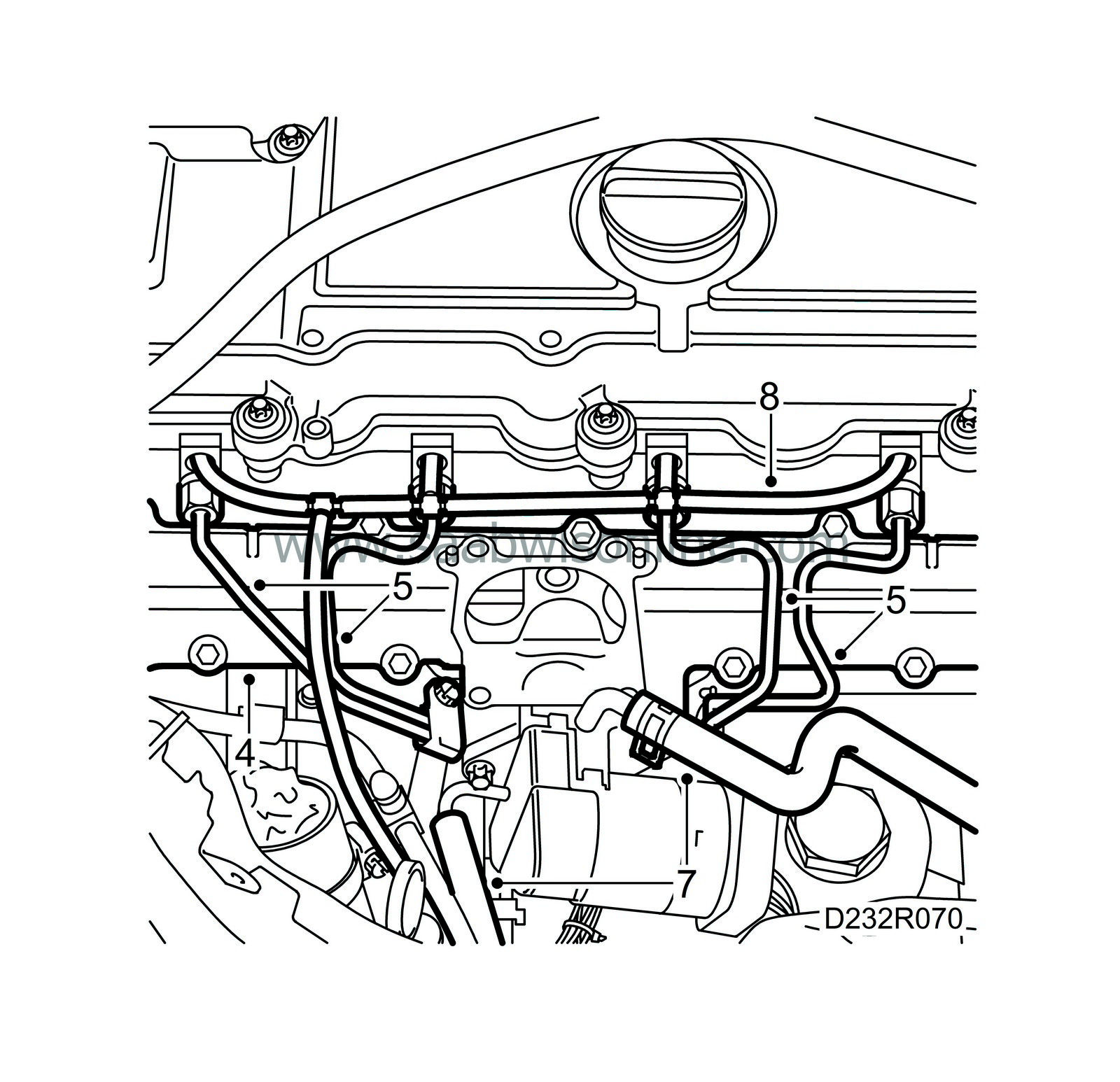
Note the position of the fuel rails and their clips and mark the pipes.

|
|
| 8. |
Remove the fuel return hoses from the fuel bridges.
|
|
| 9. |
Remove the fuel rails and clamps. Remove in the order of the cylinders.
|
|
| 10. |
Release any pressure in the cooling system by undo the expansion tank cap.
|
|
| 11. |
Clamp the coolant hoses to the EGR valve with
30 07 739 Pinch-off pliers
. Disconnect the hoses from the valve.

|
|
| 12. |
Remove the upper part of the intake manifold.
|
|
| 13. |
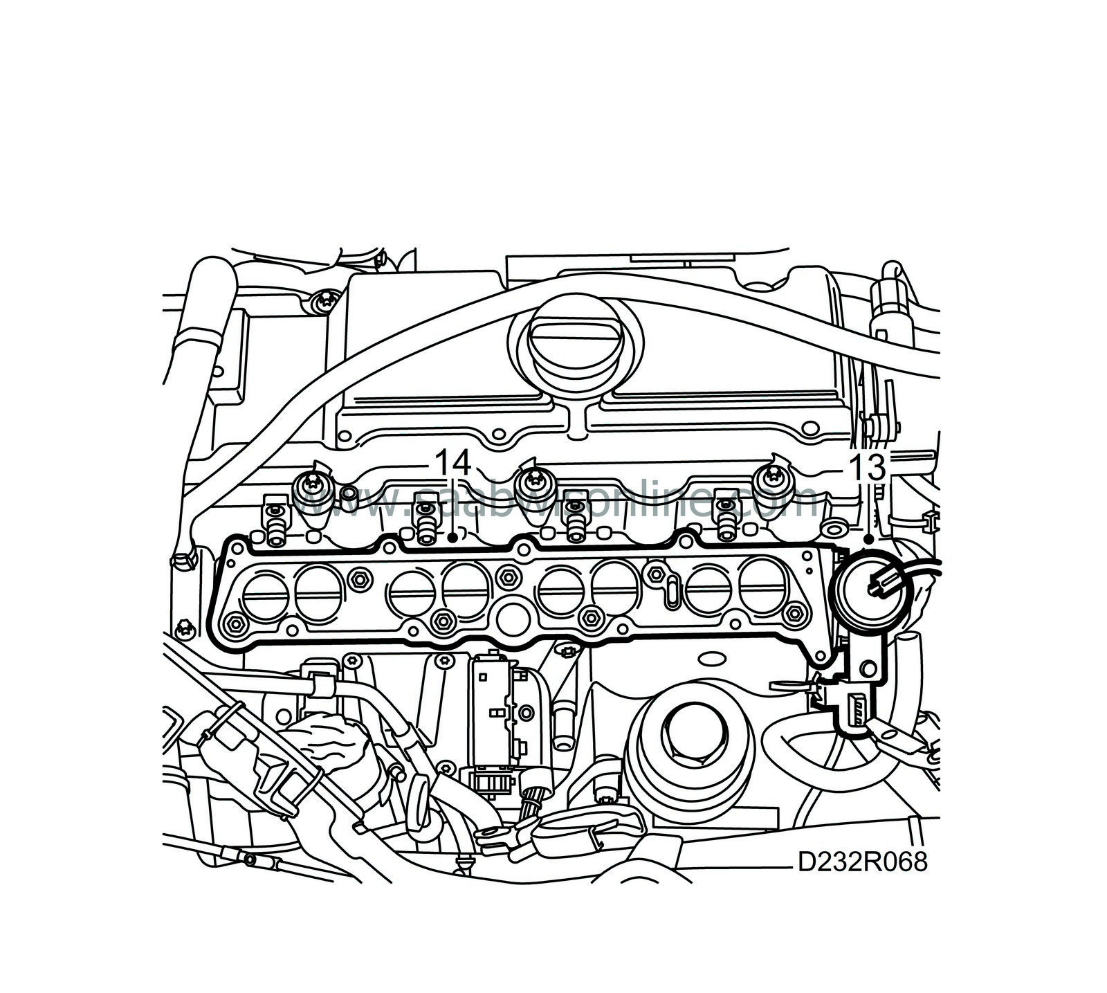
Remove the swirl throttle vacuum unit.

|
|
| 14. |
Remove the lower intake manifold.
|
|
| To fit |
| 1. |
Clean the sealing surfaces.
|
|
| 2. |
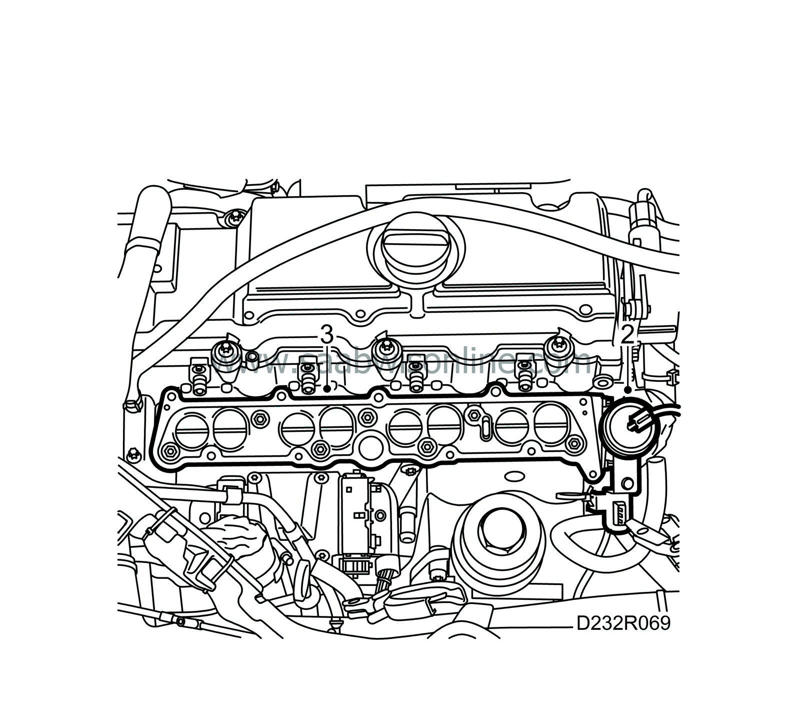
Refit the swirl throttle vacuum unit.

|
|
| 3. |
Fit a new gasket and fit the lower section of the intake manifold.
Tightening torque: 20 Nm (15 lbf ft) Tighten the bolts securing the vacuum unit. |
|
| 4. |
Fit a new gasket to the lower part of the intake manifold and fit the upper part of the intake manifold.
Tightening torque 10 Nm (7 lbf ft). 
|
|
| 5. |
Fit the fuel lines with clips to the cylinder head and fuel pump. Check the fuel rail connecting cones and replace if necessary.
Tightening torque 25 Nm (19 lbf ft) |
|
| 6. |
Check the fuel rail connecting cones and replace as necessary.
|
|
| 7. |
Connect the coolant hoses to the EGR valve.
|
|
| 8. |
Fit new fuel return hoses. Check the condition of the T-pieces and change if necessary.
|
|
| 9. |
Fit the lower clip that secures the wiring harness to the oil filter housing.

|
|
| 10. |
Fit the throttle body.
|
|
| 11. |
Plug in the timing sensor, temperature sensor and EGR valve.
|
|
| 12. |
Secure the wiring harness as it was previously and tighten the bolts.
|
|
| 13. |
Fit the hose to the intake manifold.

|
|
| 14. |
Fit the charge air pipe and secure the engine wiring harness with a cable tie.
|
|
| 15. |
Press the cable duct into place.
|
|
| 16. |
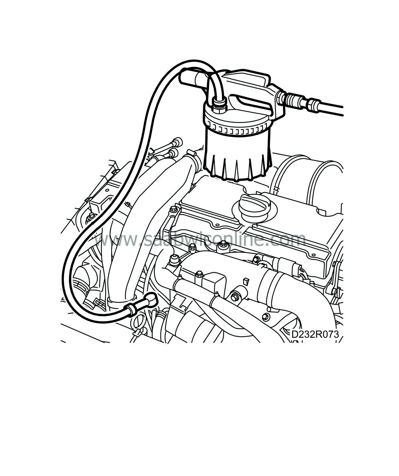
Connect
30 31 069 Nipple, bleeding equipment
to
88 19 096 Bleeding equipment
or equivalent and start the suction device.

|
|
| 17. |
Remove the end cap and connect the nipple to the service outlet on the fuel pump feed line.
|
|
| 18. |
Suck until a constant flow of fuel is seen in the suction line to the brake bleeding tool.
|
|
| 19. |
Remove the bleed nipple from the service outlet while it is still sucking (to avoid fuel spillage and air entering the system).
|
|
| 20. |
Put on the end cap for the service outlet.
|
|
| 21. |
Fit the upper engine cover.
|
|

 Warning

