
Test readings, control module connections
| Test readings, control module connections |
| Scope |
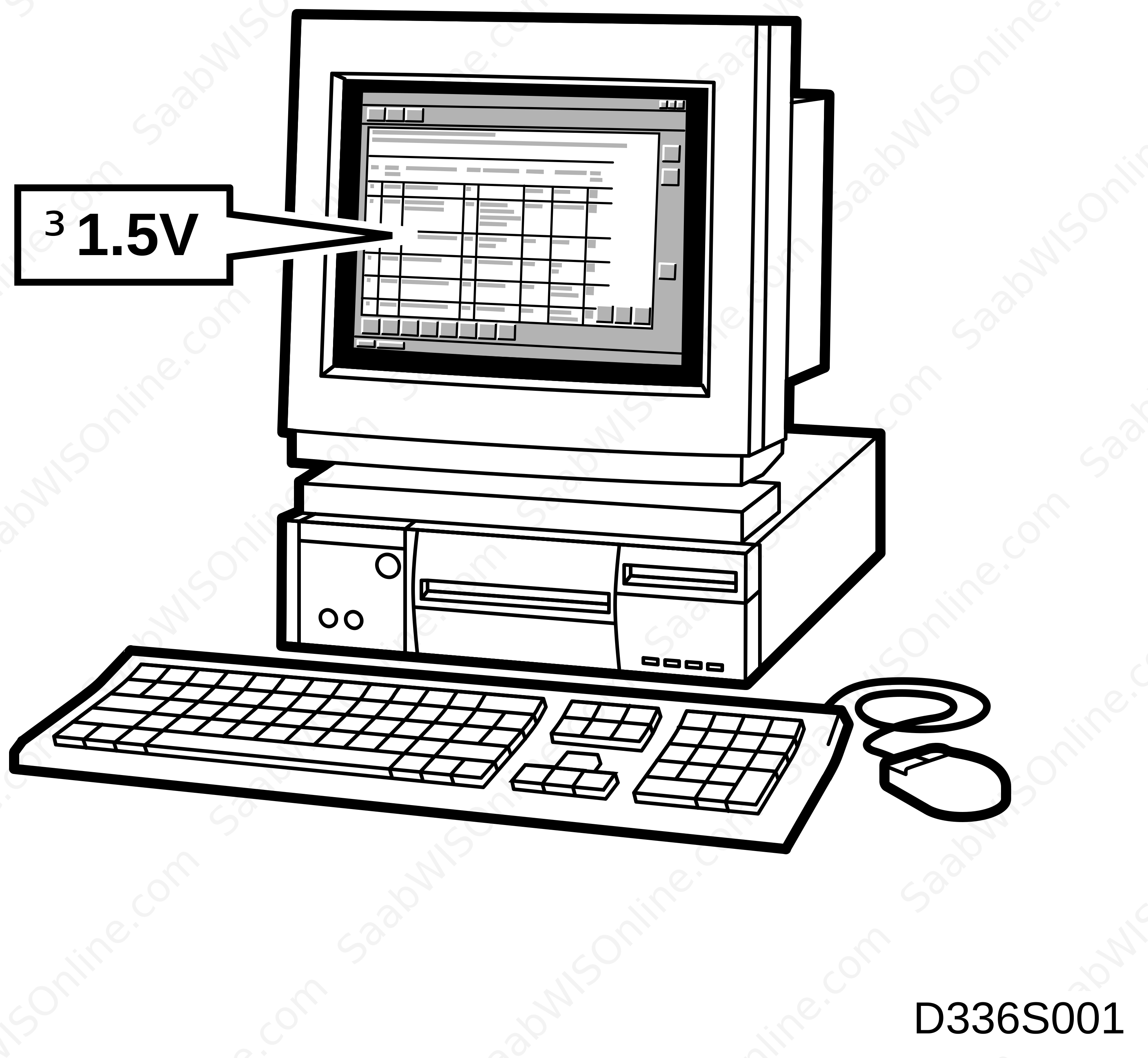
Values and directions for measuring control module voltages can be found under the relevant heading.
| Remember: |
| • |
Note the test conditions and use common sense when assessing the test result.
|
|
| • |
The specified values are with the ignition ON unless otherwise stated.
|
|
| • |
First check that the control module has a power supply and is grounded.
|
|
| • |
Then check all sensor inputs and signals from other systems.
|
|
| • |
Finally, check the control module outputs. Remember that the values do not indicate whether the actuator unit is working.
|
|
| • |
If any reading is not OK, consult the wiring diagram to trace the leads, connectors or components which should be checked more thoroughly.
|
|
| • |
The test readings given apply to a calibrated Fluke 88/97.
|
|
| • |
Test readings in %(+) and ms(+) show the pulse ratio and pulse duration of the signal. A test instrument capable of giving pulse ratio and pulse duration readings must be used. The (+) sign indicates a positive trigger pulse, TRIG+.
|
|

| Main unit connections (contacts A, B, C) |

> =greater than ; < = less than ; ~ = alternating current
(LP: LOGIC PROBE P = select pulse ; p = visible pulses
Connector (A)
Connector (B)
|
Pin No.
|
Cable colour
|
Component/
function |
In/out
|
Test conditions
|
Across
|
Test reading
|
See
|
|
1
|
BK/GN
|
Loudspeaker Right Rear (+)
|
Out
|
Music playing.
|
1(B)-8(A)
|
0-10V AC. Dependent on volume control. The test reading should vary with the volume of the music.
|

|
|
2
|
BK/WH
|
Loudspeaker Right Rear (-)
|
Out
|
Music playing.
|
2(B)-8(A)
|
0-10V AC. Dependent on volume control. The test reading should vary with the volume of the music.
|
|
|
3
|
BN/BK
|
Loudspeaker Right Front (+)
|
Out
|
Music playing.
|
3(B)-8(A)
|
0-10V AC. Dependent on volume control. The test reading should vary with the volume of the music.
|
|
|
4
|
BN/RD
|
Loudspeaker Right Front (-)
|
Out
|
Music playing.
|
4(B)-8(A)
|
0-10V AC. Dependent on volume control. The test reading should vary with the volume of the music.
|
|
|
5
|
BN
|
Loudspeaker Left Front (+)
|
Out
|
Music playing.
|
5(B)-8(A)
|
0-10V AC. Dependent on volume control. The test reading should vary with the volume of the music.
|
|
|
6
|
BN/GY
|
Loudspeaker Left Front (-)
|
Out
|
Music playing.
|
6(B)-8(A)
|
0-10V AC. Dependent on volume control. The test reading should vary with the volume of the music.
|
|
|
7
|
BN/WH
|
Loudspeaker Left Rear (+)
|
Out
|
Music playing.
|
7(B)-8(A)
|
0-10V AC. Dependent on volume control. The test reading should vary with the volume of the music.
|
|
|
8
|
BN
|
Loudspeaker Left Rear (-)
|
Out
|
Music playing.
|
8(B)-8(A)
|
0-10V AC. Dependent on volume control. The test reading should vary with the volume of the music.
|
|
Connector (C)
|
Pin No.
|
Cable colour
|
Component/
function |
In/out
|
Test conditions
|
Across
|
Test reading
|
See
|
|
1
|
BN/BK
|
Phone line input, ground
|
In
|
-
|
-
|
-
|
Telephone system
|
|
2
|
WH
|
I-BUS (-)
|
In/Out
|
Ignition ON
|
2(C)-8(A)
|
2-3 V
|
|
|
3
|
OG
|
Phone line input, signal
|
In
|
-
|
-
|
-
|
Telephone system
|
|
4
|
GN
|
I-BUS (+)
|
In/Out
|
Ignition ON
|
4(C)-8(A)
|
2-3 V
|
|
|
5
|
|
No connection
|
|
|
|
|
|
|
6
|
|
No connection
|
|
|
|
|
|
|
7
|
RD
|
Line input CD changer
Left (-) |
In
|
Music playing.
|
7(C)-9(C)
|
0-2 VAC. The test reading should vary with the volume of the music.
|
|
|
8
|
BN
|
Line input CD changer
Right (-) |
In
|
Music playing.
|
8(C)-10(C)
|
0-2 VAC. The test reading should vary with the volume of the music.
|
|
|
9
|
BU
|
Line input CD changer
Left (+) |
In
|
Music playing.
|
9(C)-7(C)
|
0-2 VAC. The test reading should vary with the volume of the music.
|
|
|
10
|
GN
|
Line input CD changer
Right (+) |
In
|
Music playing.
|
10(C)-8(C)
|
0-2 VAC. The test reading should vary with the volume of the music.
|
|
| Main unit connections (DIN connector) |
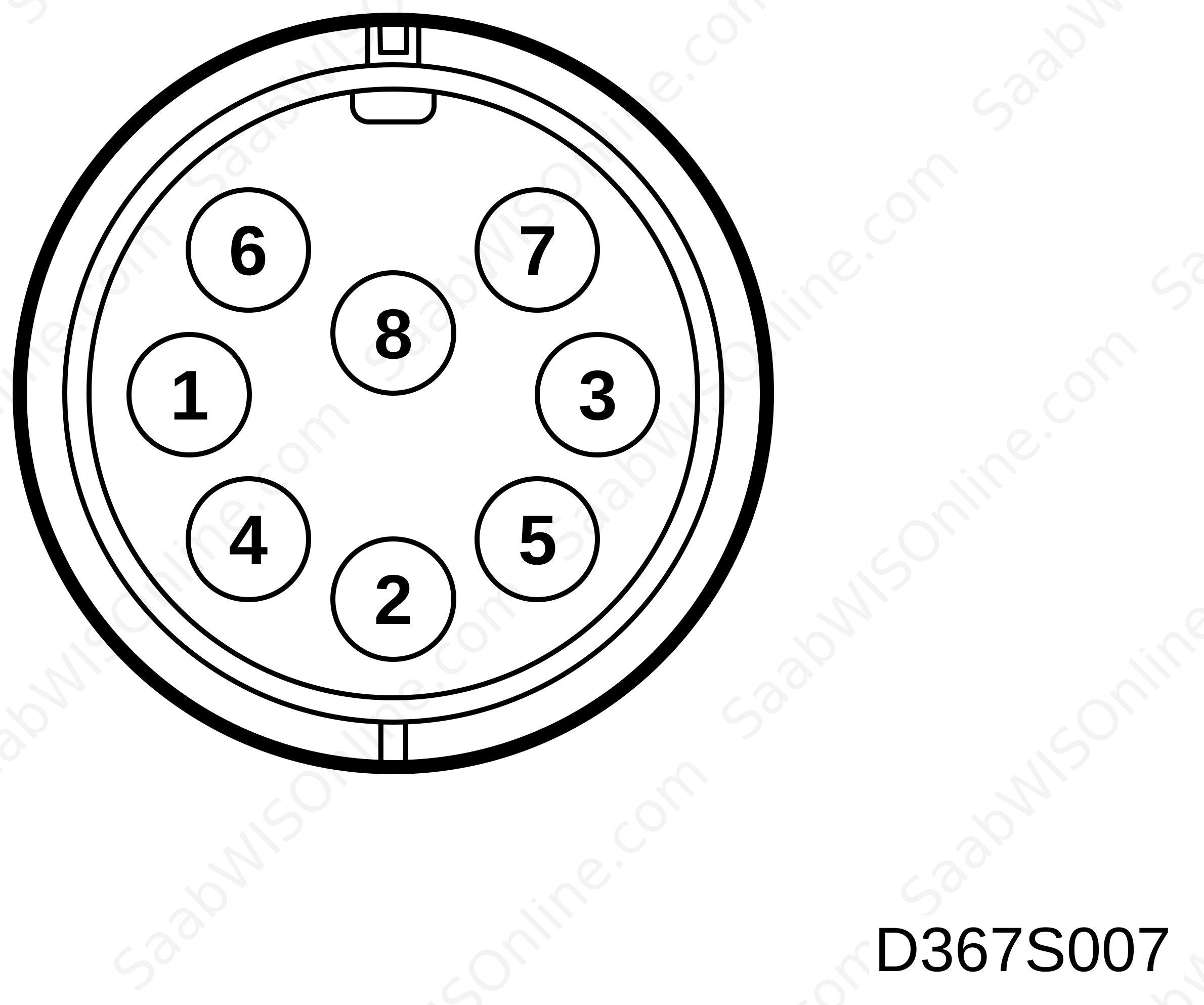
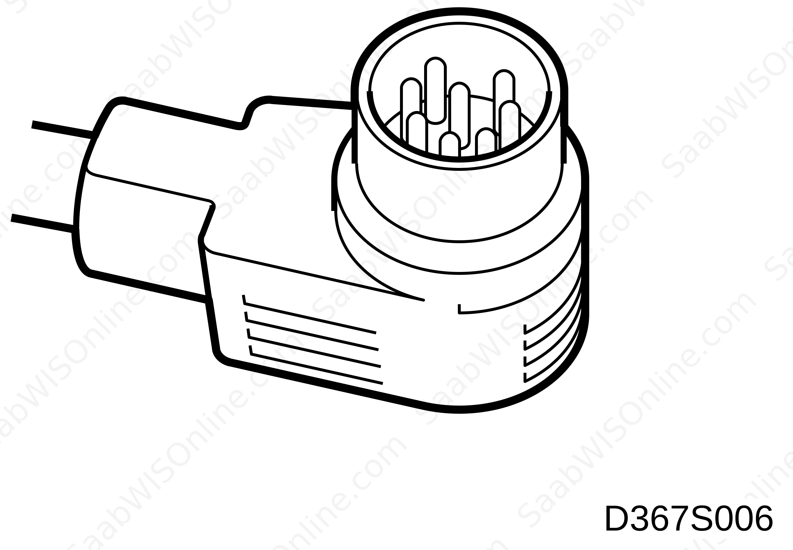
|
Pin No.
|
Cable colour
|
Component/
function |
In/out
|
Test conditions
|
Across
|
Test reading
|
See
|
|
1
|
|
Line output, external amplifier. Signal, left rear.
Not used. |
Out
|
|
|
|
|
|
2
|
|
Signal ground, screen
|
|
|
|
|
|
|
3
|
|
Line output, external amplifier.
Signal, left front. |
Out
|
|
3-2
|
|
|
|
4
|
|
Line output, external amplifier. Signal, right rear.
Not used. |
Out
|
|
|
|
|
|
5
|
|
Line output, external amplifier.
Signal, right front |
Out
|
|
5-2
|
|
|
|
6
|
|
Mute control
|
Out
|
|
|
|
|
|
7
|
|
No connection
|
|
|
|
|
|
|
8
|
|
Trigger voltage
|
Out
|
Main unit on.
Main unit off. |
8-2
|
B+
0 V |
|
This project is supported by memberships and donations. If you use this site, please consider Joining SCNA and/or making a donation.
Our Friends