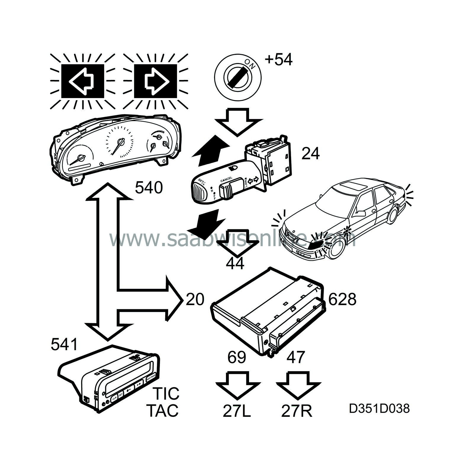
Direction indicators
| Direction indicators |
When the indicator stalk switch is pushed upwards (right) or downwards (left), voltage B+ is fed through the switch to the control module's:
| • |
pin 20 for LH direction indicators
|
|
| • |
pin 44 for RH direction indicators
|
|
The control module then delivers voltage pulses to the indicator lamp in question from:
| • |
pin 69 for LH direction indicator
|
|
| • |
pin 47 for RH direction indicator
|
|
DICE monitors the direction indicator circuits internally by measuring the current through and voltage across a resistor inside the control module on pin 22. If the current/voltage ratio changes, DICE reacts. In the event of overloading, DICE switches the output off. For underloading, DICE increases the flash frequency.
The normal flash frequency is 90±5 flashes per minute. When the circuit load is low, i.e. the rating of the lamp bulb is too low or the bulb has failed, the flash frequency is doubled.
Power to the direction indicators on a trailer connector is fed via connector 258.
Active right-hand or left-hand direction indicator is indicated with the respective indicator lamp (540) in the main instrument unit MIU when information (ON/OFF) has been received via the bus.
Active direction indicators are also indicated acoustically with a "tick-tock" sound, which is generated in the SID unit after it receives information about the direction indicators from the bus.
If there is no voltage on the control module pin 22, no information is sent to the bus.


