Test readings, AHS/PHM - Auxiliary heater
|
|
Test readings, AHS/PHM - Auxiliary heater
|
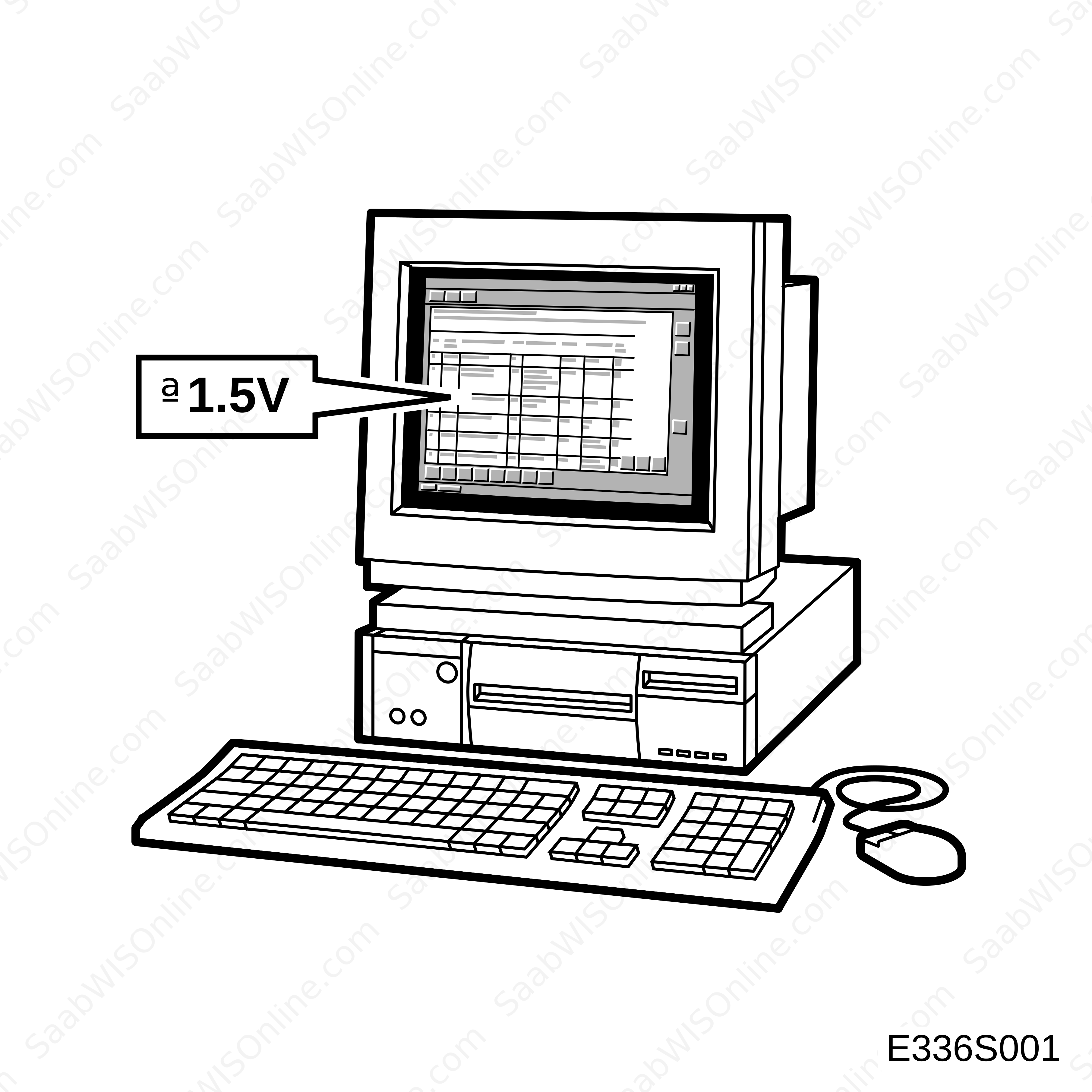
 The following pages contain readings and directions for testing signals and levels on the main instrument unit and its control module.
|
•
|
Note the test conditions and use common sense when assessing test results.
|
|
•
|
First check that the control module has a power supply and is grounded.
|
|
•
|
Then check all sensor inputs and signals from other systems.
|
|
•
|
Lastly, check the control module outputs. Remember, the readings do not say anything about whether or not the actuator is in working order.
|
|
•
|
If any reading is not OK, consult the wiring diagram to trace the leads, connectors or components which should be checked more thoroughly.
|
|
•
|
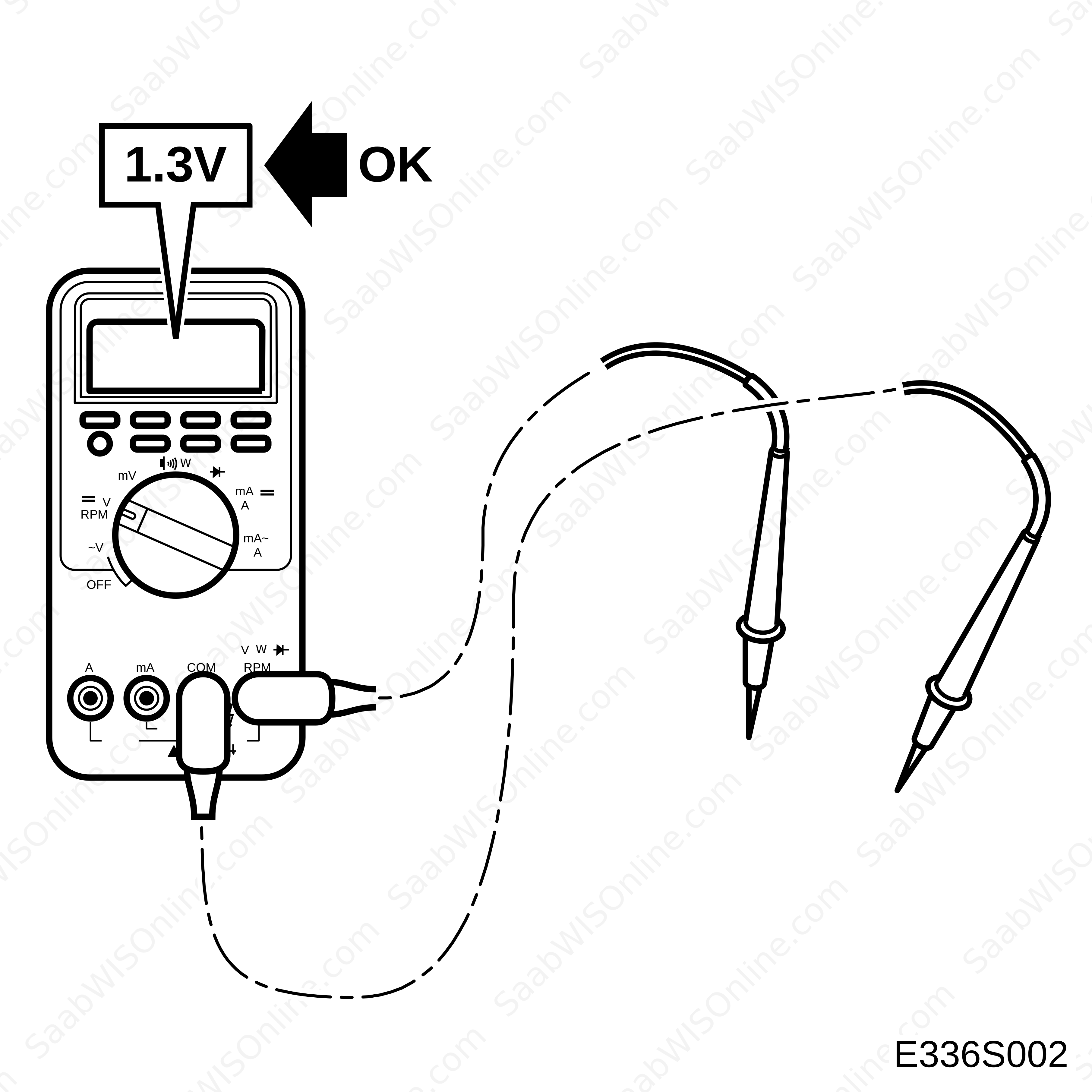
The specified test readings refer to those obtained with a calibrated Fluke 88/97.
|
|
•
|
Test readings %(+) and ms(+) show the signal's pulse ratio and pulse width. A test instrument with pulse ratio and pulse width measurement must be used. The sign (+) indicates a positive trigger pulse, TRIG+.
|
|
Control module connections
|
K1
|
Pin
|
Component/Function
|
In/Out
|
Test conditions
|
Across
|
Test reading
|
|
1
|
+30
|
|
|
1-B+
|
<0.5V
|
|
2
|
Ground
|
|
|
2-B+
|
<0.1V
|
|
3
|
LS-BUS
|
|
|
|
|
|
4
|
No connection
|
|
|
|
|
|
5
|
No connection
|
|
|
|
|
|
6
|
Fuel pump (+)
|
Out
|
|
6-2
|
10 ohms
|
K2
|
Pin
|
Component/Function
|
In/Out
|
Test conditions
|
Across
|
Test reading
|
|
1
|
Water pump +30
|
|
|
|
|
|
2
|
Water pump Ground
|
|
|
1 and 2
|
13V
|