Fault in PSG16 difficult to locate despite DTC being generated
Symptom: The car may exhibit fault symptoms when a DTC for electrical fault in the engine control system has been generated but the cause of the fault has not been found despite repeated fault diagnosis.
This can be due to loose pins causing poor contact in any of the connectors to the engine control module. The following fault diagnosis includes a general fault diagnosis of the connectors to the engine control module.
|
|
Fault in PSG16 difficult to locate despite DTC being generated
|
Fault symptom
The car may exhibit fault symptoms when a DTC for electrical fault in the engine control system has been generated but the cause of the fault has not been found despite repeated fault diagnosis.
This can be due to loose pins causing poor contact in any of the connectors to the engine control module. The following fault diagnosis includes a general fault diagnosis of the connectors to the engine control module.
Criteria
If a DTC occurs, the respective fault diagnosis should be used to start with. If this is not successful, carry out the following measures.
Procedure
|
1.
|
Read fault codes from the engine control module. Note the fault codes for further fault diagnosis.
|
|
2.
|
Check the wiring diagram for the engine control system. Note which pins and connectors belong to the component/fault for which the DTC applies.
|
|
3.
|
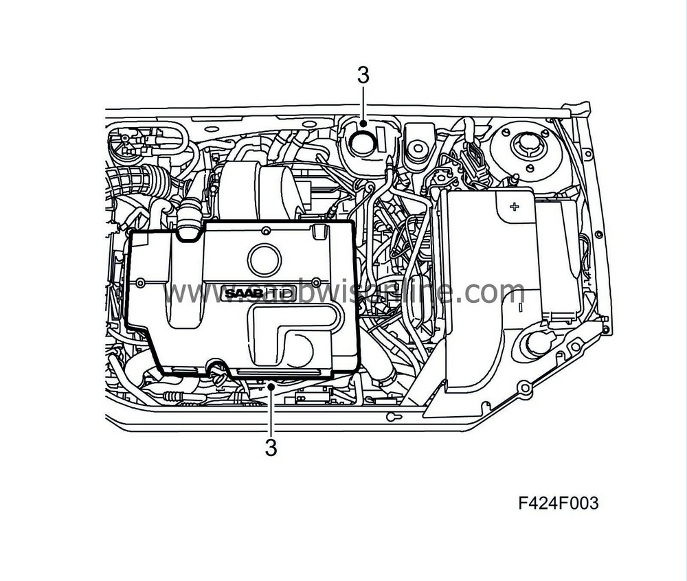
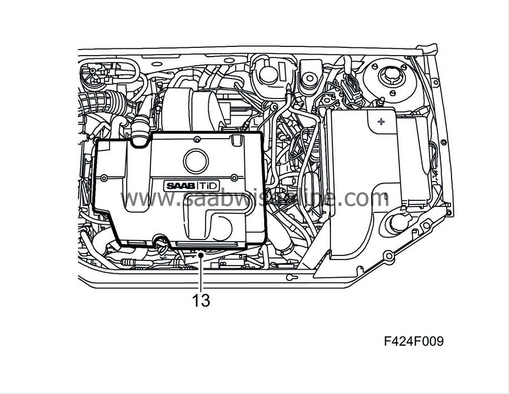
Remove the upper engine cover and undo the lid on the expansion tank to release the pressure in the cooling system.
|
|
4.
|
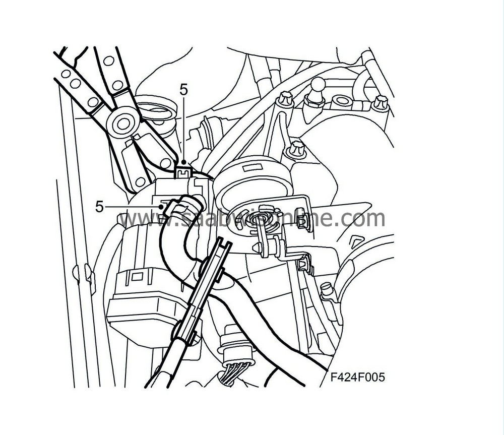
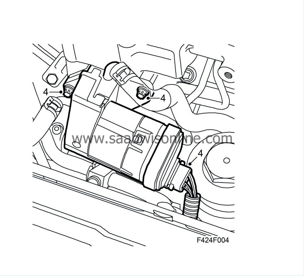
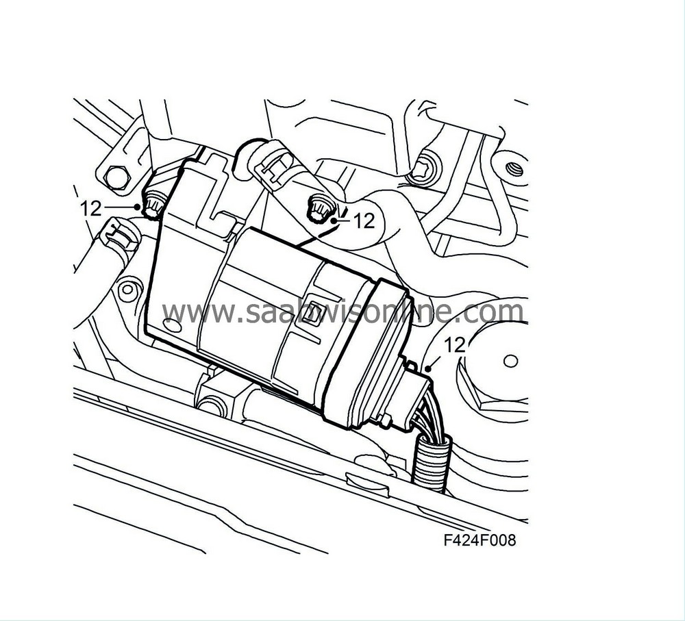
Unplug the connector and remove the EGR valve from the intake manifold.
|
|
6.
|
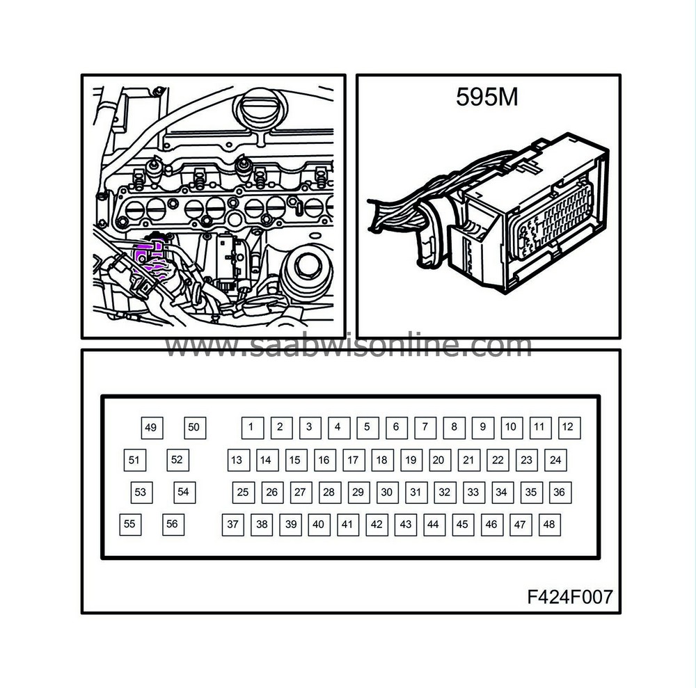
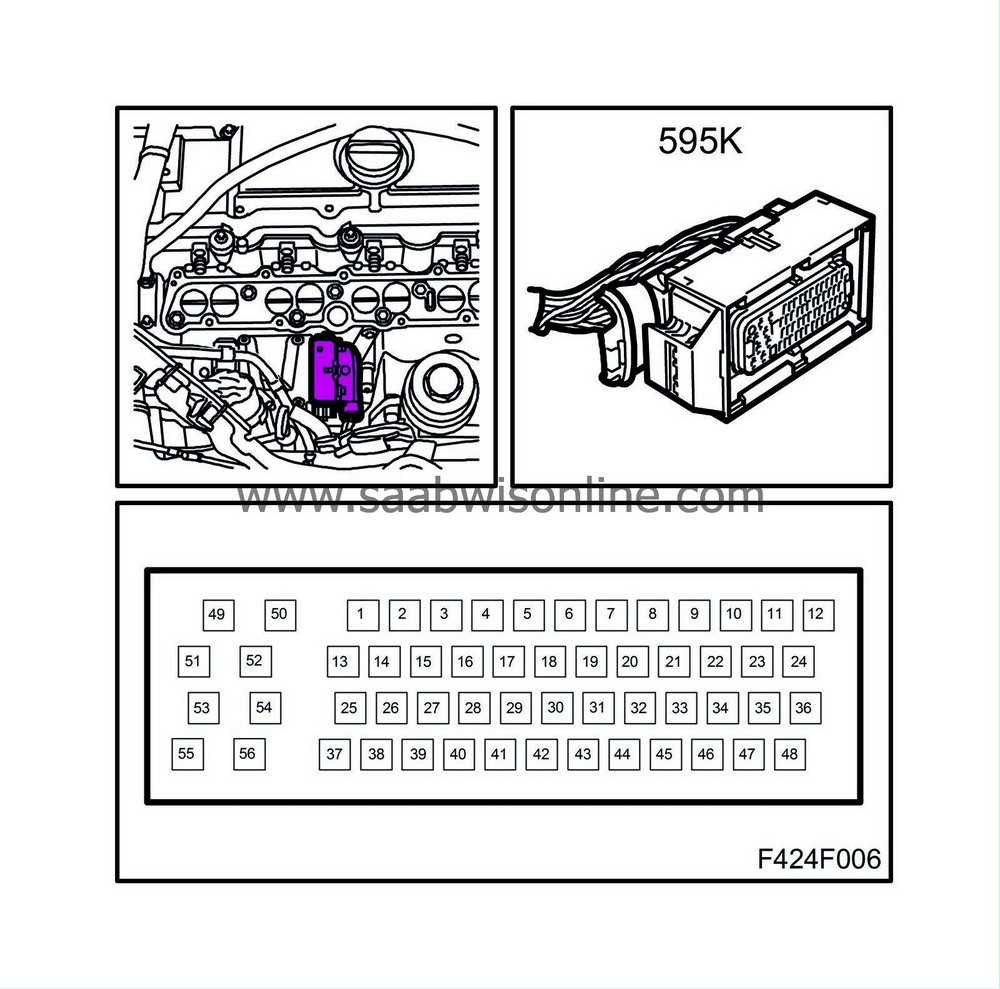
Unplug either one or both of the connectors from the engine control module depending on the component/function undergoing fault diagnosis.
|
Important
|
|
ESD-SENSITIVE COMPONENT
|
|
Earth yourself by touching the car body before plugging in/unplugging components.
Do not touch the component pins, see
Removing electronic components
.
|
|
|
|
|
7.
|
Expose the connector so that the pins that are affected according to the notes made in step 2 can be thoroughly checked.
|
|
8.
|
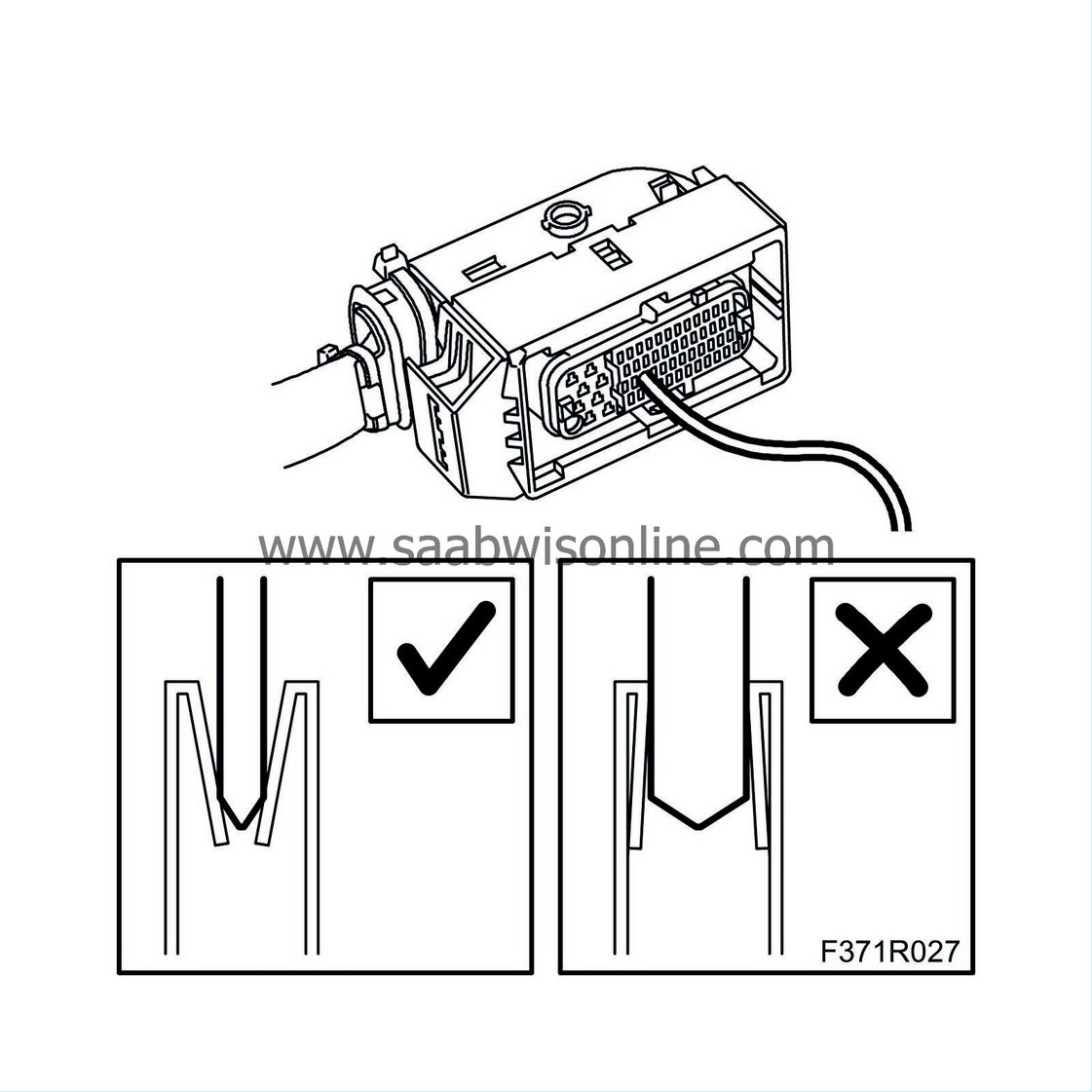
Use a test cable with pin size 0.6 x 0.6 mm from kit 86 12 731. Insert the test cable pin into the connector pin to feel the pinching force on the affected pins. Check also that the pins engage the same depth as the other pins in the connector.
Poor pinching force and shallow pin engagement in the connector can cause poor contact.
|
Important
|
|
Incorrect handing or the use of the wrong tool can damage the sleeves in the connector.
|
|
Use a test cable (part no. 86 12 731) of the correct size to avoid damaging the sleeves in the connector.
|
|
|
|
|
9.
|
If a loose pin or one with weak pinching force is found, the engine wiring harness must be changed.
|
|
10.
|
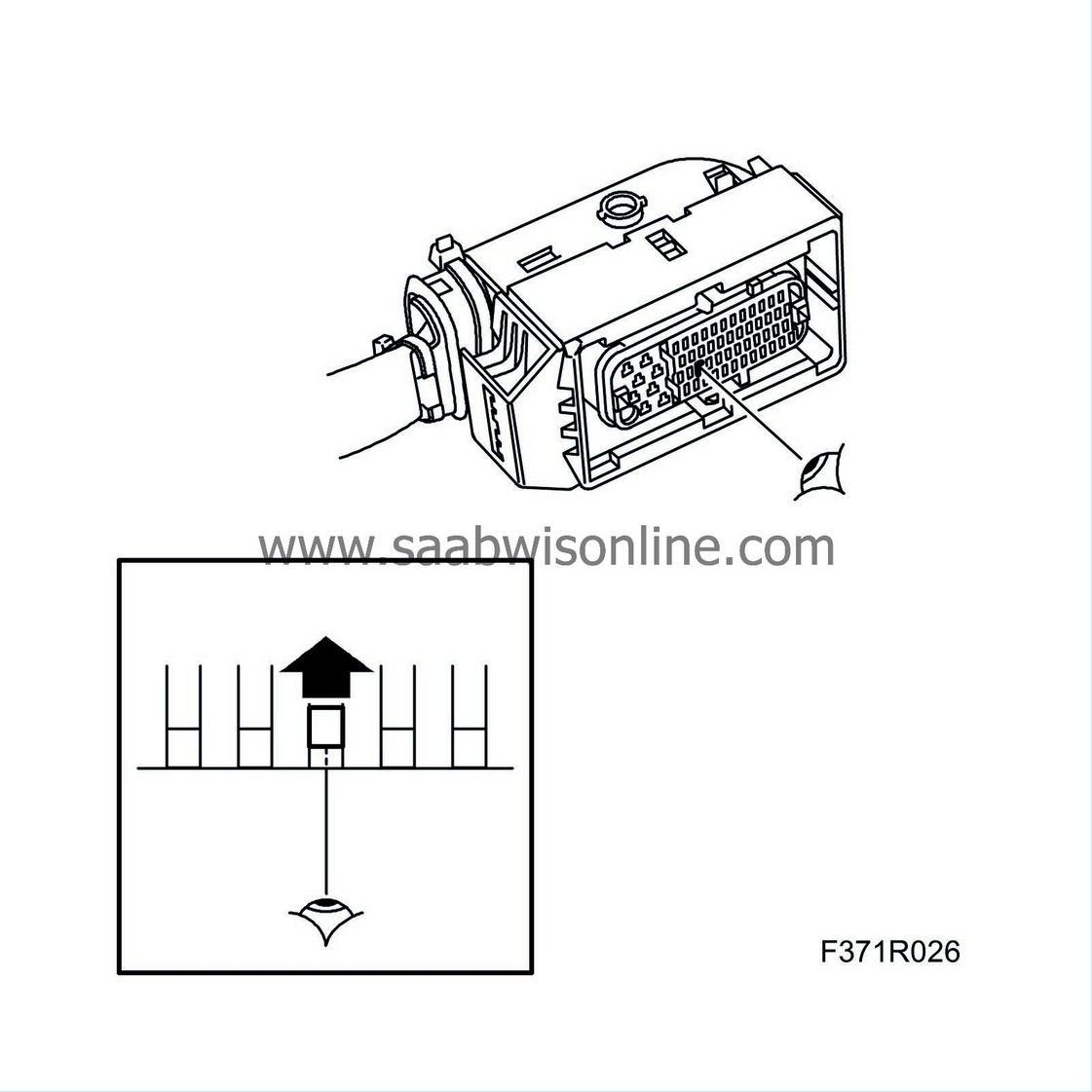
Use a mirror to check that the engine control module pins are straight.
|
Important
|
|
ESD-SENSITIVE COMPONENT
|
|
Earth yourself by touching the car body before plugging in/unplugging components.
Do not touch the component pins, see
Removing electronic components
.
|
|
|
|
|
11.
|
Plug in the engine control module connector.
|
|
12.
|
Fit the EGR valve.
|
|
13.
|
Fit the upper engine cover.
|
|
14.
|
Read the control module software version with Tech 2. If there is a later software version in TIS2000 then this must be programmed into the control module.
|
|
15.
|
Carry out one driving cycle, i.e. drive the car at varying loads and engine speeds for five minutes.
|
|
16.
|
Check with Tech2 that the DTC has not returned.
|
|
17.
|
If the problems have not been solved, please contact the importer's technical support.
|


