Detailed description, engine management
| Detailed description, engine management |
| - |
Desired value calculation
|
|
| - |
Actual boost pressure and atmospheric pressure
|
|
| - |
Boost pressure control
|
|
Desired value calculation
Desired value calculation uses the following parameters:| - |
Engine speed
|
|
| - |
Requested fuel quantity
|
|
| - |
Atmospheric pressure from atmospheric pressure sensor
|
|
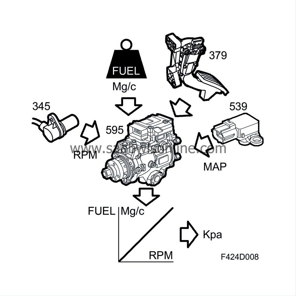
To determine the desired value for boost pressure, a value is taken from a control map based on engine speed and injected fuel quantity. This value is corrected for atmospheric pressure.
Actual boost pressure and actual atmospheric pressure
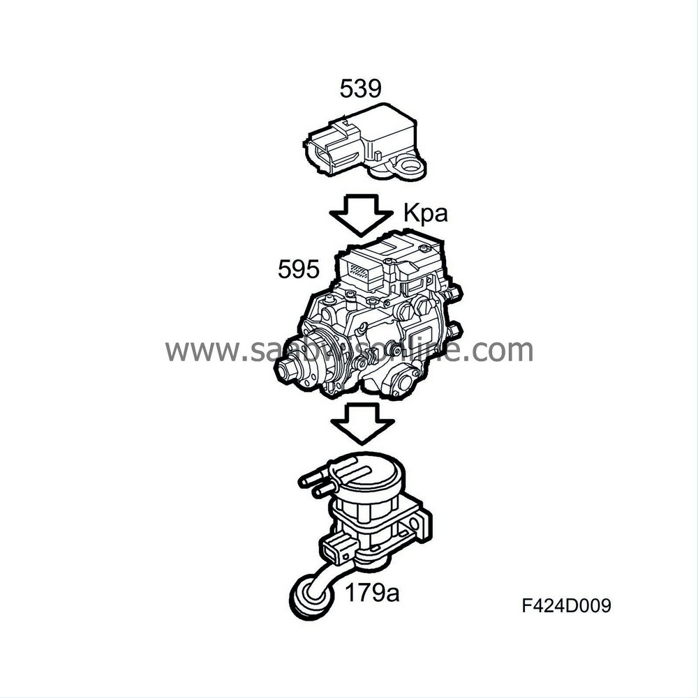
The boost pressure is measured by the pressure sensor (688) in the intake manifold, and is filtered before being sent to the control module.The atmospheric pressure is measured by the atmospheric pressure sensor (539) which is located on the left-hand side of the radiator.
Boost pressure control
The pulse ratio is controlled when the following criteria are fulfilled: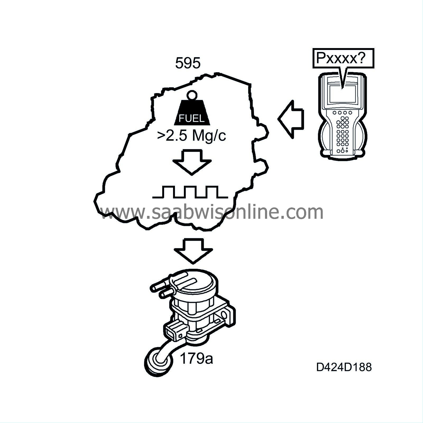
| - |
No DTC related to the mass air flow sensor, EGR or turbo control.
|
|
| - |
Quantity of injected fuel exceeds 2.5 mg/combustion.
|
|
The desired boost pressure is converted using pre-programmed parameters to a pulse ratio. The value is then conveyed to the power amplifier control, where the signal is amplified and compensated for the battery voltage, see table.
| Voltage (V) | Compensation value |
| 9 | 1.4 |
| 14.2 | 1.0 |
| 16 | 0.775 |
The value is compensated since a voltage that is higher or lower than 14.2 V will produce a different valve lift and consequently control the solenoid valve incorrectly.
The pulse ratio is then available on pin 13 of the control module for connection to the boost pressure control valve.
The diagnostic tool displays the value for the boost pressure control valve as a percentage. 65% PWM means that the boost pressure control valve is closed.
When a DTC related to boost pressure control is generated in PSG 16, the engine torque is limited.
| Fuel |
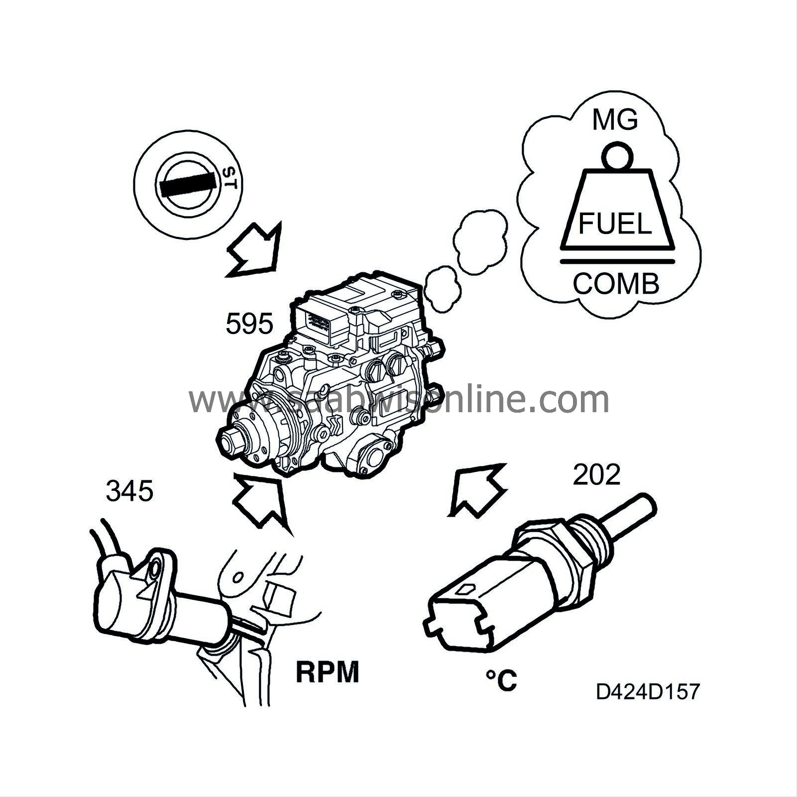
Calculation of starting fuel quantity
The starting fuel quantity is the amount of fuel allowed when starting the engine. The function is activated when starting the engine is possible and is terminated at engine speeds above 750 rpm. If starting from cold, the function is deactivated at a considerably higher engine speed.The fuel quantity is calculated using the following sub-functions:
Base value
A base value is retrieved for which the starter motor speed and engine coolant temperature are the input values.
Starting quantity correction
The starting quantity correction is calculated from the current engine speed. The max. correction is 5 mg/combustion and it decreases with increasing engine speed (0 mg/combustion at 750 rpm).
Starting quantity enrichment
Starting quantity enrichment ensures problem-free starting at all temperatures. Enrichment is calculated from the pump temperature, engine speed and the time it takes for the engine to start. Different parameters are selected for cold starting enrichment depending on whether the pump temperature is above or below 10°C.
The results of these calculations are totalled and form the total starting fuel quantity.
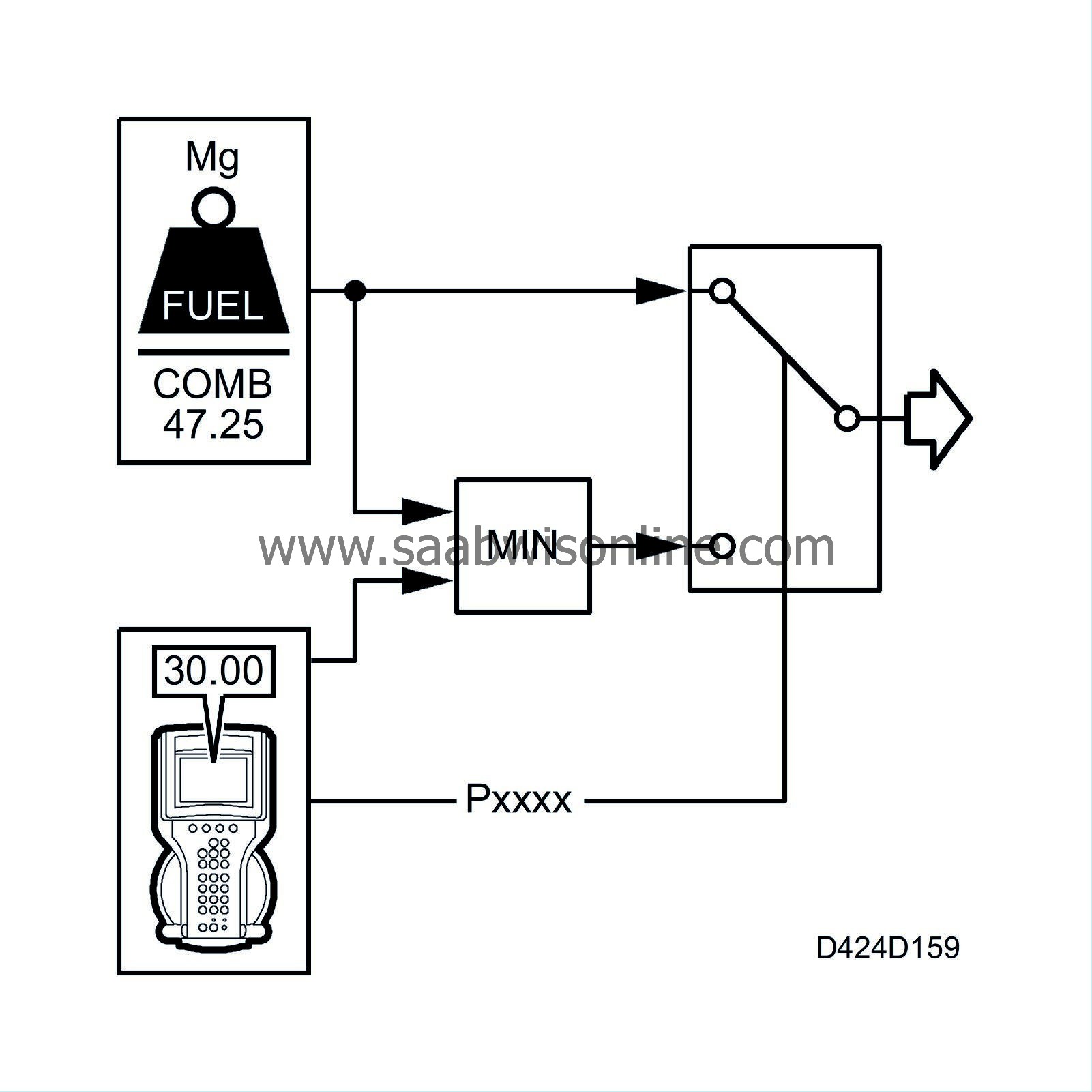
The starting fuel quantity can be decreased or increased by 5 mg/combustion with the diagnostic tool.
Limit quantities
The sub-functions under limit quantities calculate the largest permitted injection quantity in mg/combustion for the current operating conditions. The calculated limit quantity is used to limit the requested quantity from the pedal position sensor and the cruise control, if it should be necessary. The calculation is performed at fixed time cycles, independent of the engine speed.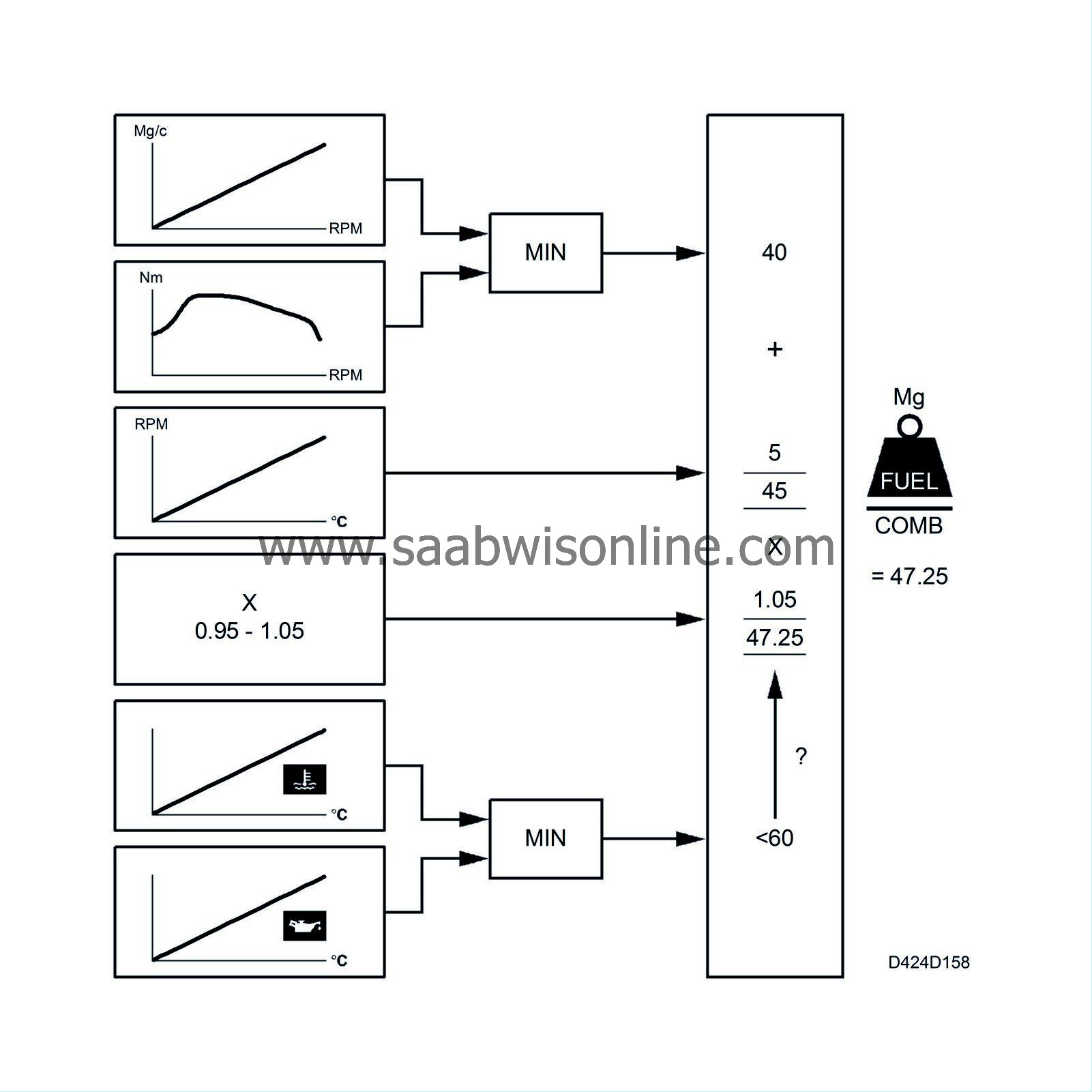
| 1. |
The results of the calculations in the smoke limitation and torque limitation sub-functions are compared and the function that gives the lowest injection quantity is the value that is carried forward.
Example: The result of smoke limitation is 40 mg/combustion and the result of the torque limitation is 60 mg/combustion. This means that the value from the smoke limitation (40 mg/combustion) is carried forward. |
|
| 2. |
The result of the temperature compensation is added to the result of the calculation above.
Example: 40 mg/combustion + 5 mg/combustion = 45 mg/combustion. |
|
| 4. |
However, if there is a system fault, 45 mg/combustion is compared with the limit quantity on system fault (rpm dependent, max. 30 mg/combustion), and the lowest value is carried forward as the limit quantity.
|
|
Smoke limitation
There is a smoke limitation function to prevent the formation of large amounts of smoke.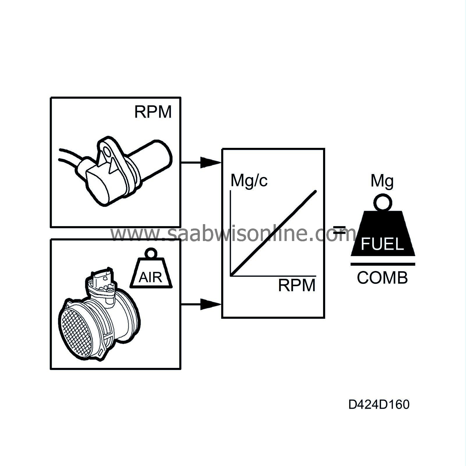
Smoke limitation is calculated from the engine speed, absolute pressure and the intake air mass in mg/combustion. The function is tested so that the fuel quantity in mg/combustion always has sufficient air mass/combustion to prevent smoke formation.
If this is not the case, smoke limitation is activated and the fuel quantity is reduced to a level at which the available air mass is sufficient to burn the fuel without the formation of large amounts of smoke. This takes place when driving at high altitudes, for example, as the proportion of oxygen in the air decreases at higher altitudes.
Torque limitation
To adapt the torque of the engine, a torque limitation quantity based on the engine speed is obtained. This value is proportional to the value from the throttle potentiometers.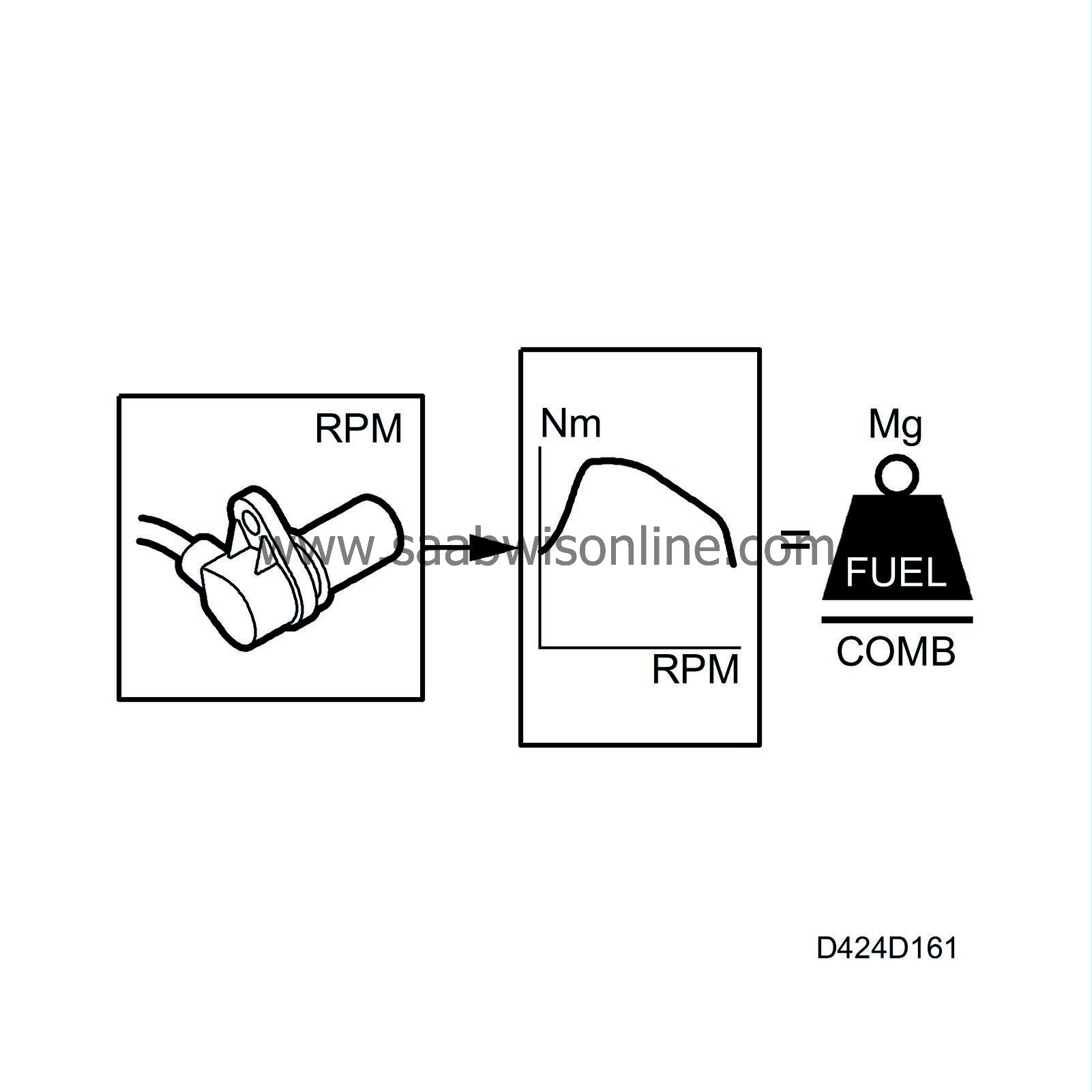
Temperature compensation
Enrichment is required when the engine is cold to ensure good driveability. On the other hand, if the engine is about to overheat, this function is activated to reduce the fuel quantity.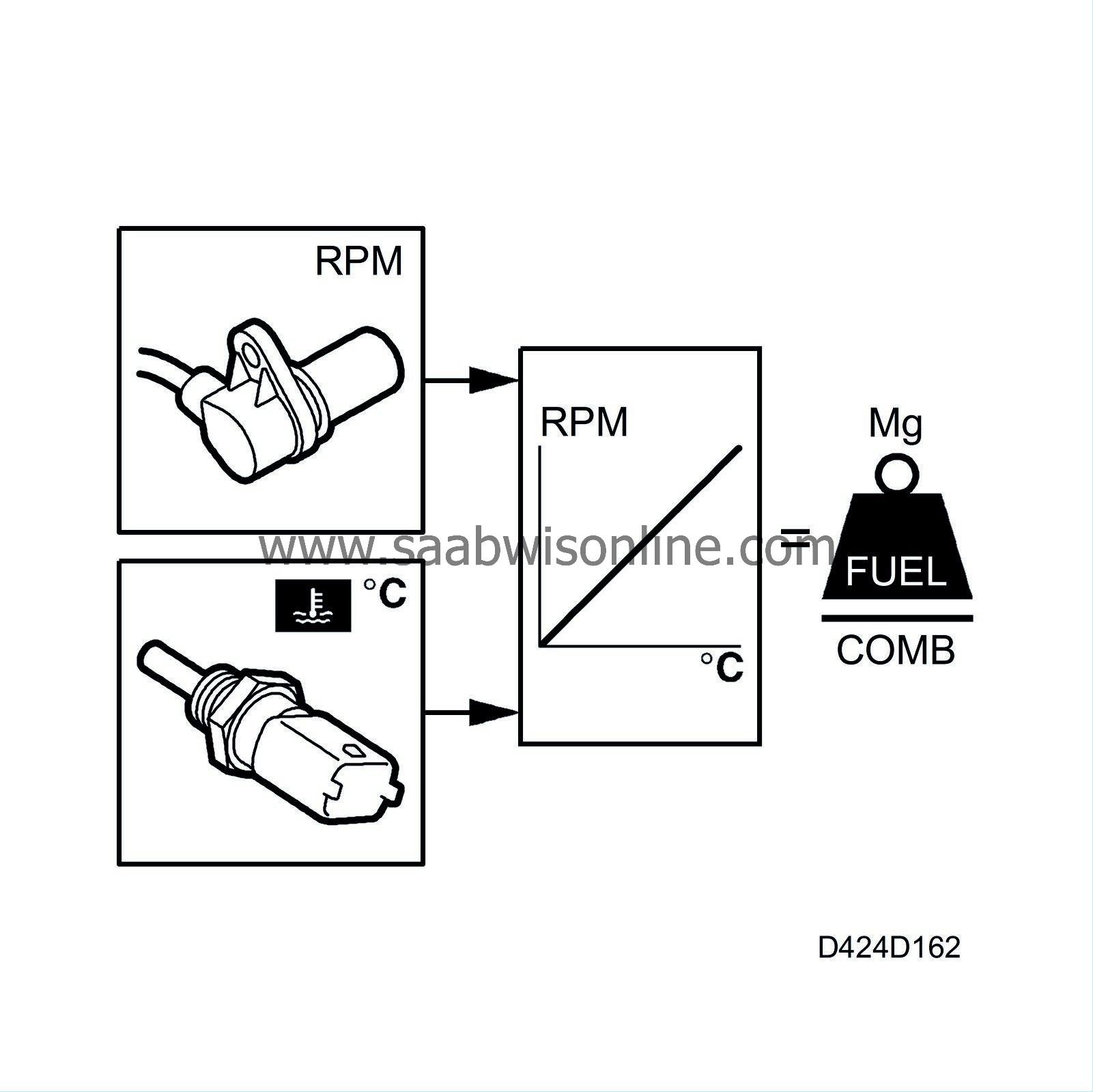
Information used to control this functions comes from:
| • |
Oil temperature sensor
|
|
| • |
Coolant temperature sensor
|
|
| • |
Fuel temperature sensor
|
|
Quantity compensation
Due to variations in the diesel fuel, its density may vary. This means that at lower densities, the car will have less power than expected or, if the diesel fuel has a high density, the car will tend to issue more smoke from the exhaust. To compensate for this, there is a quantity compensation function.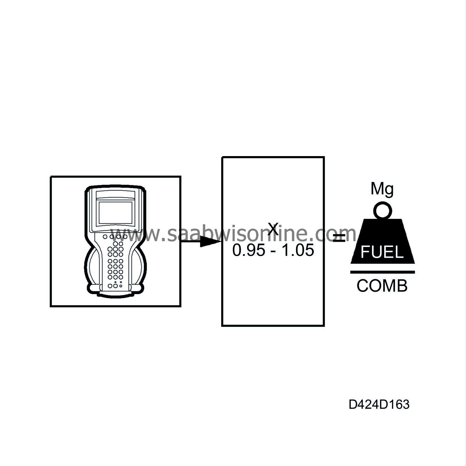
The limits are quantity compensated by multiplying them by a value between 0.95 and 1.05 mg/combustion.
Quantity compensation can be adjusted 5% using the diagnostic tool.
Overheating protection
If the engine coolant temperature, fuel temperature or engine oil temperature becomes too high, the overheating protection is activated and the permitted fuel quantity is reduced.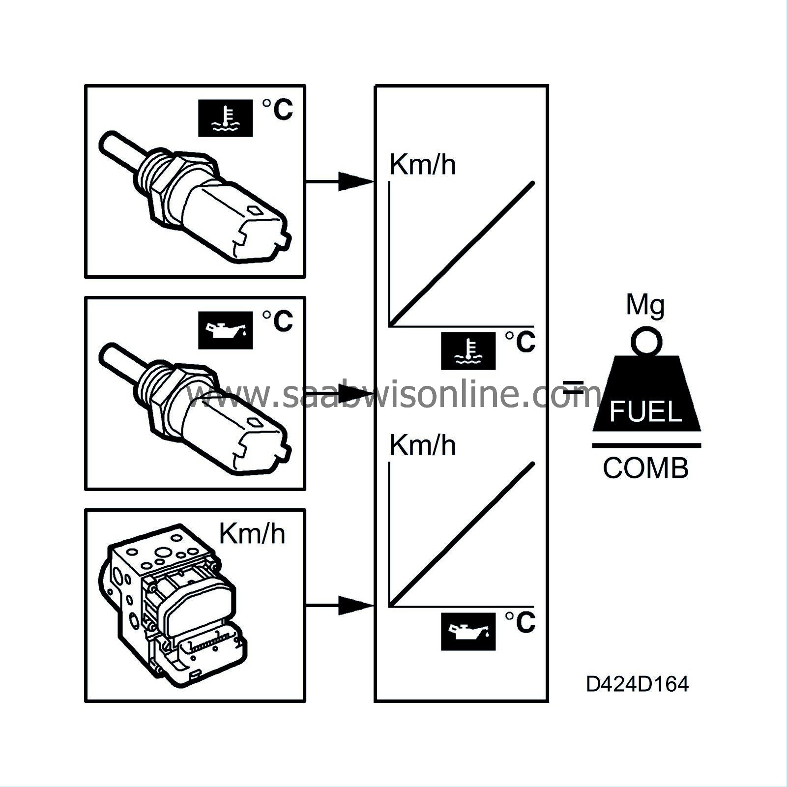
The overheating protection function reduces the fuel quantity depending on the engine coolant temperature and the vehicle speed, the fuel temperature, or engine oil temperature and the vehicle speed. The limit that results in the smallest injection quantity is the value that is applied.
The reduction is considerable and is clearly noticeable while driving. This occurs so that the engine temperature can be stabilized so that the engine is not damaged. The A/C is switched off.
If overheating protection has been activated, a diagnostic trouble code is generated that can be read on the diagnostic tool. The diagnostic trouble code is cleared after 60 starts with a fault-free system, or with the diagnostic tool.
Requested quantity from accelerator position sensor
The requested torque is sent from the pedal position sensor to the PSG 16 engine control module. The control module adjusts the fuel quantity/combustion so that this agrees with the requested torque.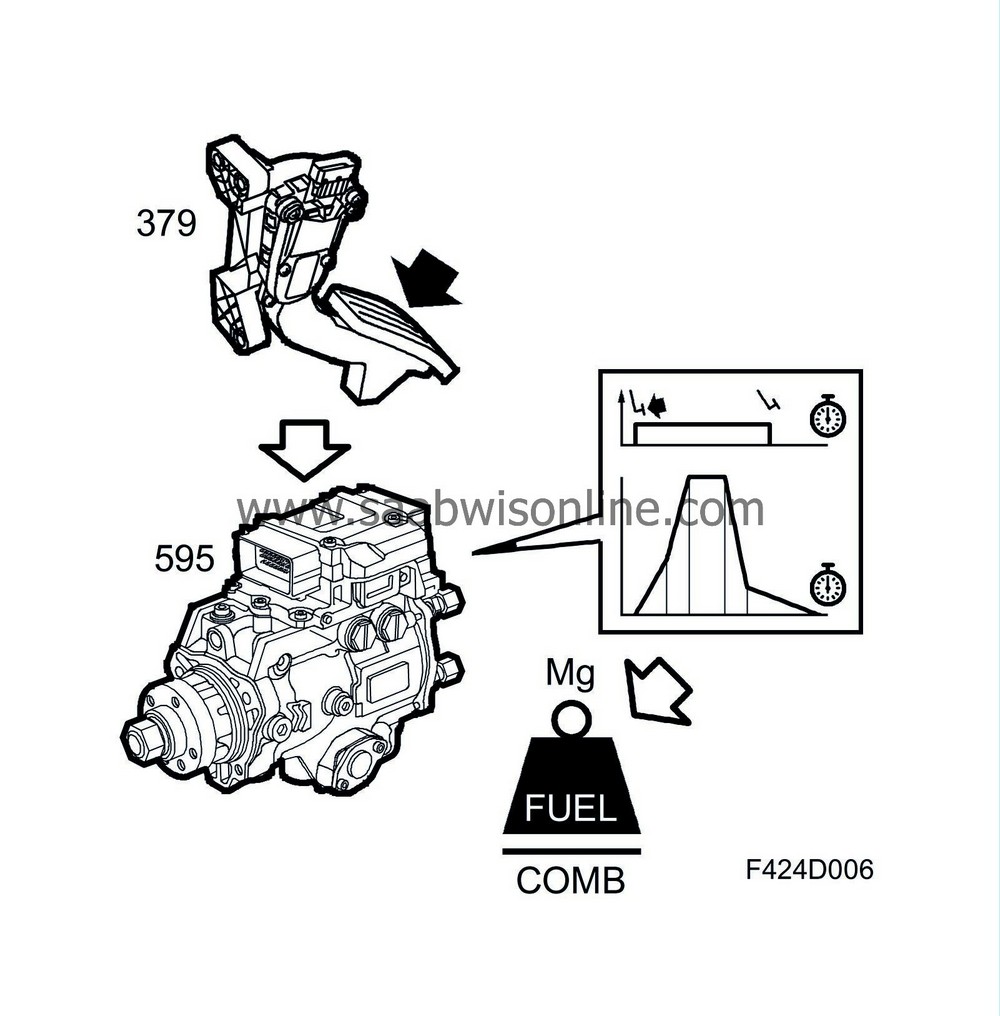
The value from the pedal position sensor is filtered during acceleration and deceleration.
Compensation for A/C compressor operation
This function is activated when the A/C compressor starts, compensating for the extra torque that the A/C compressor takes from the engine with an extra fuel quantity/combustion.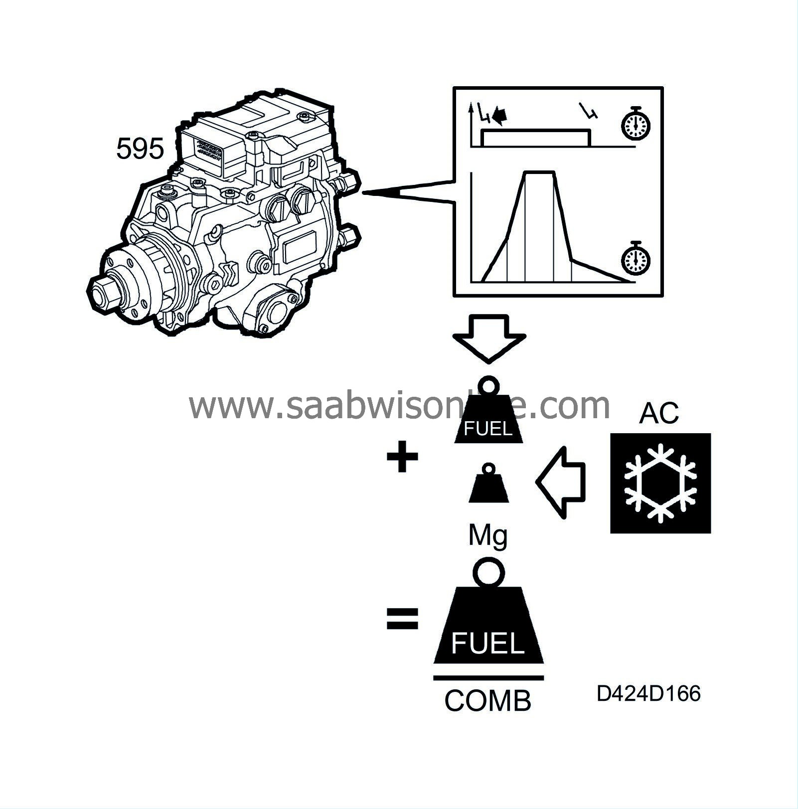
The compensatory quantity from the "compensation A/C compressor operation" function is added to the value "requested quantity from pedal position sensor". The compensatory fuel quantity depends on the pressure in the A/C system and is approx. 2-3 mg/combustion.
PSG 16 reads the A/C pressure from the bus.
| Engine shut-off |
The PSG 16 control module can choose between two methods of turning off the engine when the ignition is turned to OFF.
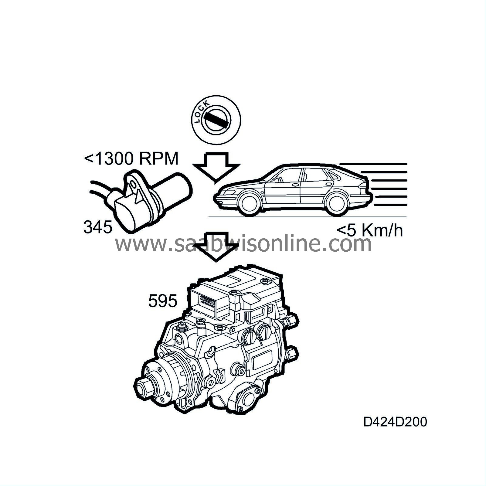
The normal method is when the control module energizes the high-pressure control valve in the diesel pump. This is done by pin 105 on the control module going high, which makes the engine stop due to the control valve remaining closed so that the high-pressure pump cannot supply fuel for injection. This method is used if the vehicle speed is less than 5 km/h and the engine speed less than 1300 rpm.
If the above conditions are not met, the engine is turned off by the desired value of the injection quantity being set to 0 mg/combustion.
Diagnostics
If the vehicle speed is less than 5 km/h and the engine speed less than 1300 rpm when the ignition is turned to OFF (+15 low), the engine speed should drop to below 200 rpm after 1.3 seconds.
If the engine speed is not less than 200 rpm after 1.3 seconds, diagnostic trouble code P0606 will be generated and the engine turned off. This is done by setting the desired value of the injection quantity to 0 mg/combustion.
Afterrunning
Afterrunning is a function that is activated when the engine control module pin 16 (+15) has become dead, i.e. the ignition has been turned to OFF. The control module determines whether the main relay should be turned off or not based on the presence or absence of + 15.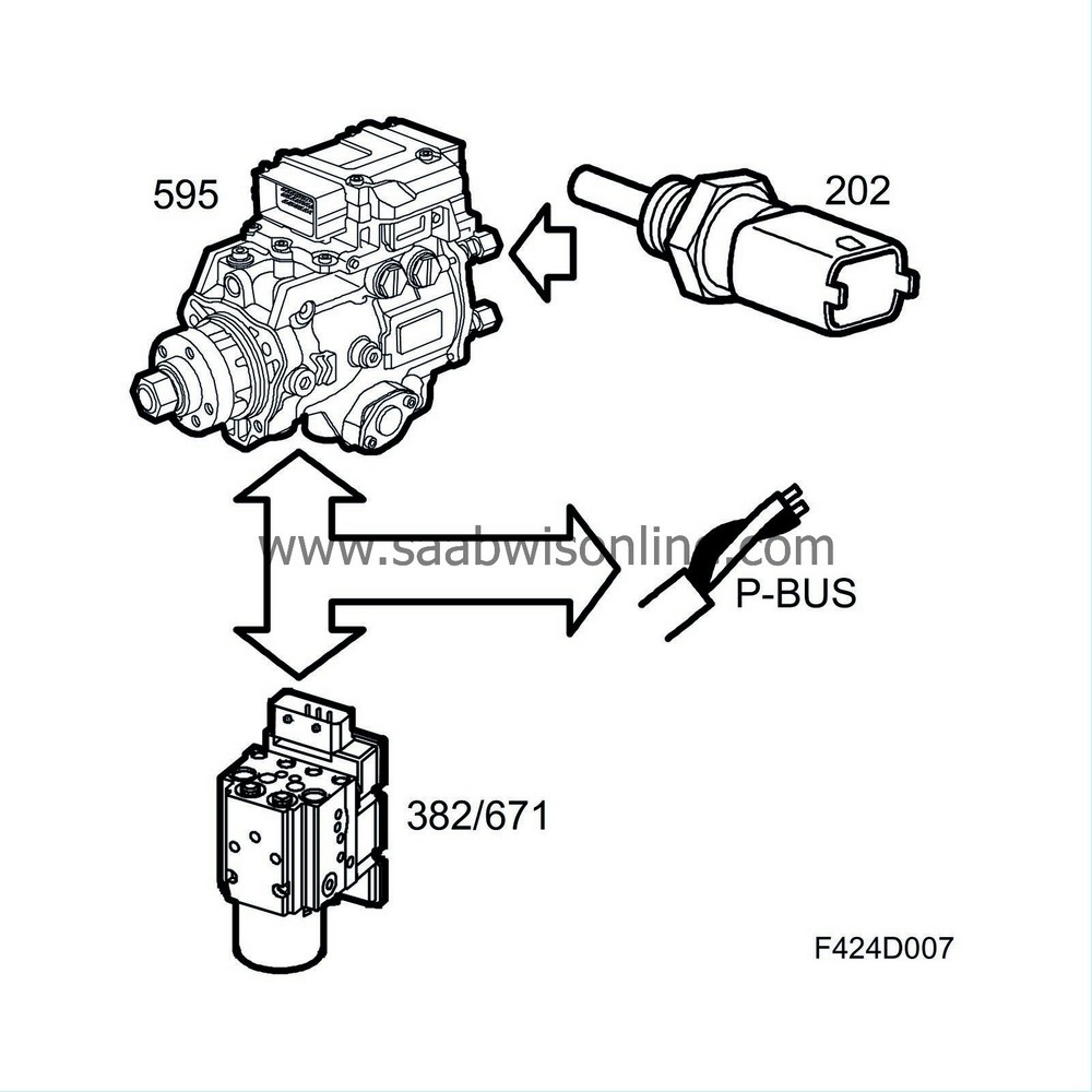
+15 absent
If +15 disappears, the ignition is considered to be in the OFF position. The proper afterrunning then starts.+15 present
If +15 is present, the ignition is considered to be in the ON position. If +15 disappears less than 1 second after being connected, the control module automatically goes over to afterrunning.Afterrunning duration
Afterrun time 1 second. Any trouble codes and diagnosis of the main relay are stored.Checking solenoid valve cut-off
If the vehicle speed is below 5 km/h and the engine speed below 1300 rpm, the solenoid valve cut-off is tested. The engine is then turned off only by the cut-off valve. If the engine speed then drops below 200 rpm within 1.3 seconds, the solenoid valve cut-off function is correct. If this does not happen, a diagnostic trouble code is generated.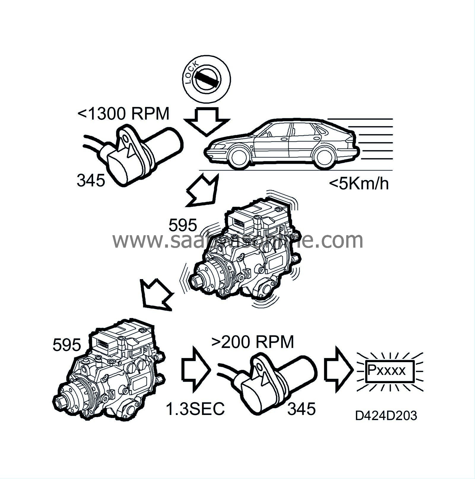
If a fault in the cut-off valve is registered or if the vehicle or engine speed limits are exceeded, the injected fuel quantity will be set to 0 mg/combustion. If the vehicle or engine speed limits are exceeded, the solenoid valve cut-off cannot be tested as the engine will stop anyway, because the injected fuel quantity has been set to 0 mg/combustion.
Storing diagnostic trouble codes
This sub-function stores all the diagnostic trouble codes in an EEPROM memory so that they are available even when the power supply to the main relay has been shut off.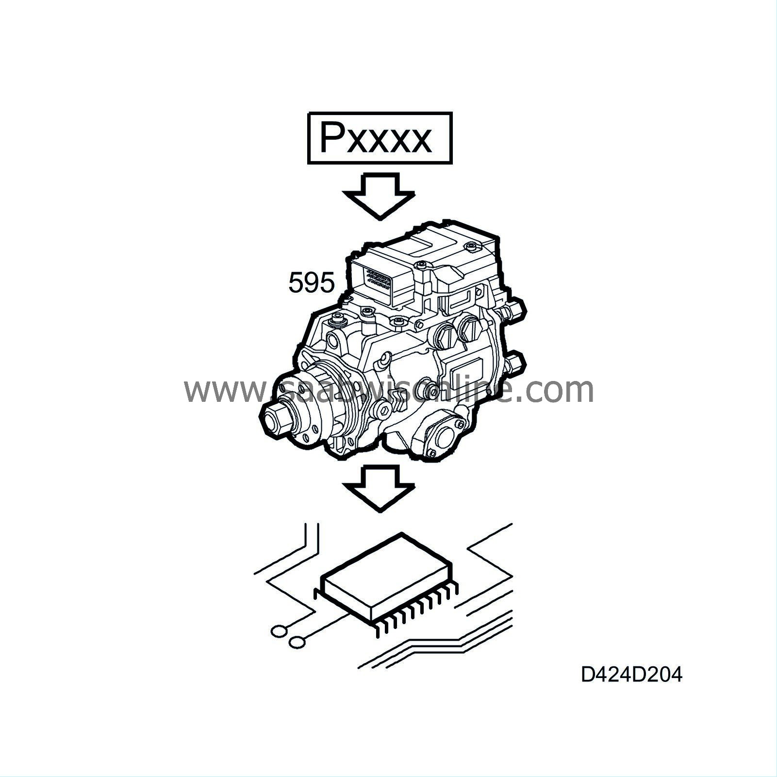
If a diagnostic cycle is running, it will be allowed to finish before the next afterrun sub-function, checking the main relay, is activated.
Checking the main relay shut-off
When the engine control module gives the command for turning off the main relay, a clock in the control module starts to record the time from when the command was given to when the main relay is actually turned off.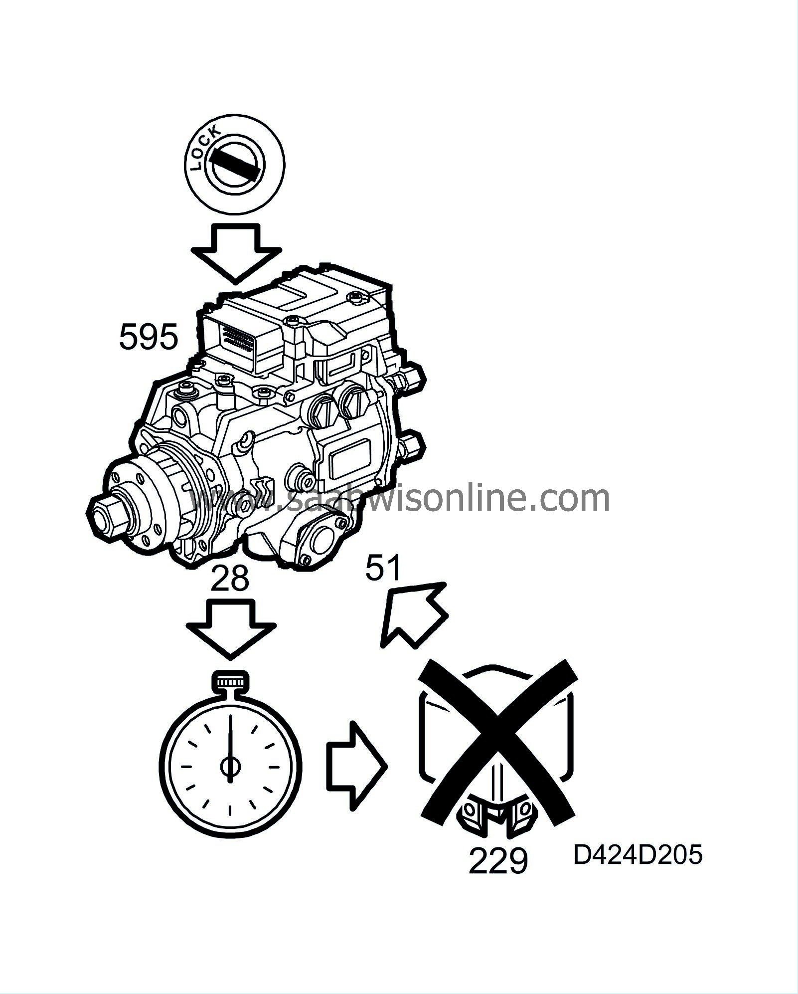
Diagnostics If any of the following diagnostic trouble codes are generated, the CHECK ENGINE lamp will go on the next time the ignition is turned to ON.
| - |
The time interval between the command and the main relay turning off is greater than 3 seconds. This means that the relay is defective and diagnostic trouble code P1652 will be generated.
|
|
| - |
The power supply is cut during operation. This generates diagnostic trouble code P1653.
|
|
Cut-off damper
The cut-off damper is mounted on a shaft in the intake manifold. A control valve connected to the shaft controls the position of the damper.When the engine is switched off, a solenoid valve opens and produces a negative pressure in the damper control valve, which then closes the cut-off damper. This prevents air entering the intake manifold.
This ensures that the engine does not continue to run uncontrolled and reduces the risk of pulses in the intake manifold, which reduces the risk of the mass air flow sensor becoming dirty when the engine is switched off.
| Miscellaneous |
Torque limitation on erroneous ignition timing
If a DTC related to erroneous ignition timing is generated that causes torque limitation, the values listed below apply: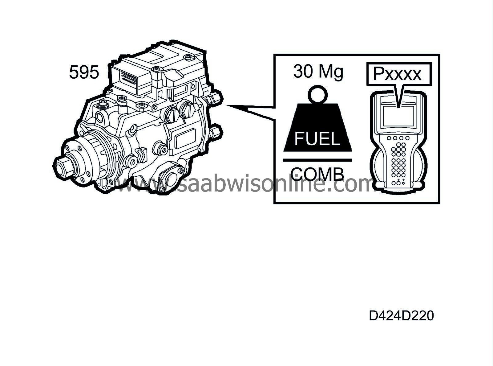
| Engine speed (rpm) | Fuel quantity (mg/combustion) |
| 0 | 0 |
| 20 | 30 |
| 1000 | 30 |
| 1250 | 30 |
| 2250 | 20 |
| 2500 | 0 |
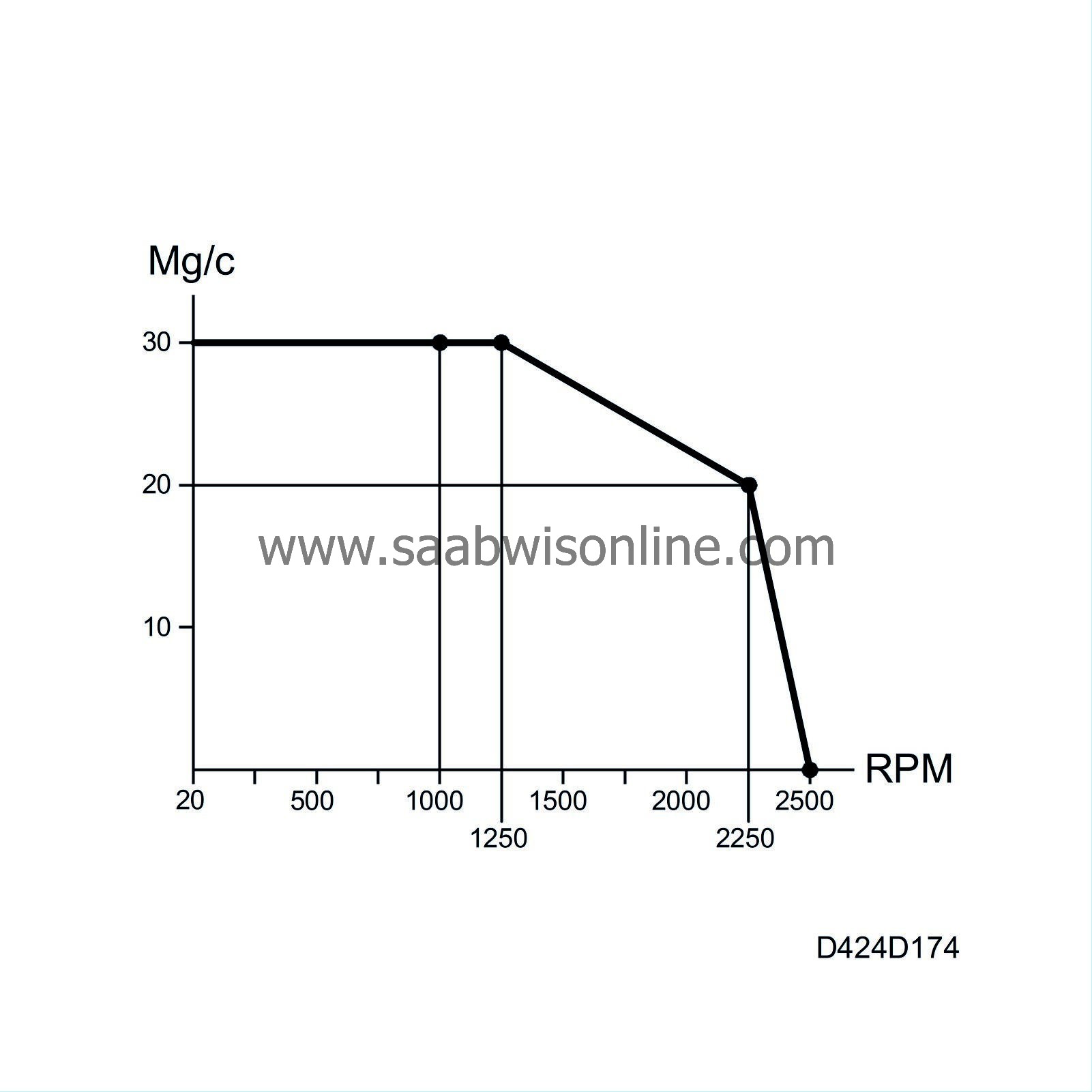
Torque limitation on faulty turbo control, mass air flow sensor or EGR control
If a DTC related to faulty turbo control, the mass air flow sensor or the EGR valve is generated that causes torque limitation, the values listed below apply:
| Engine speed (rpm) | Max. torque |
| 0 | 0 |
| 20 | 200 |
| 1000 | 200 |
| 2250 | 170 |
| 2500 | 120 |
| 3000 | 70 |
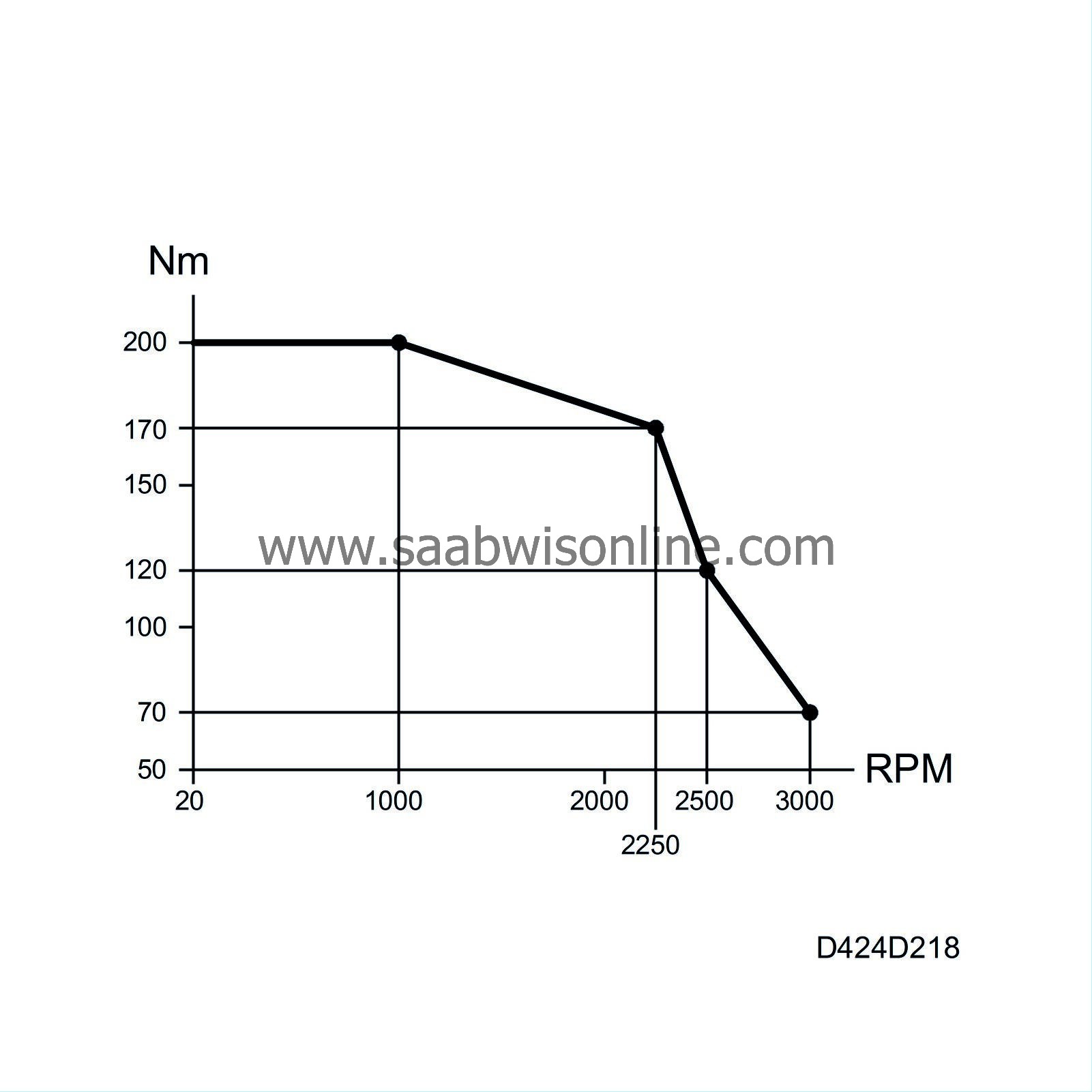
Torque limitation on erroneous throttle control
If a DTC related to erroneous throttle control is generated, the engine speed will be set to a fixed 1400 rpm.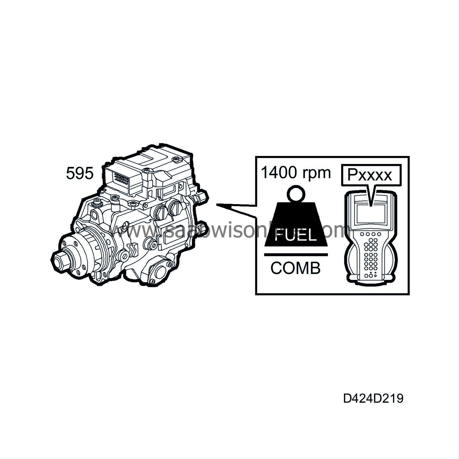
Idle speed control
Idle speed control comprises two sub-functions: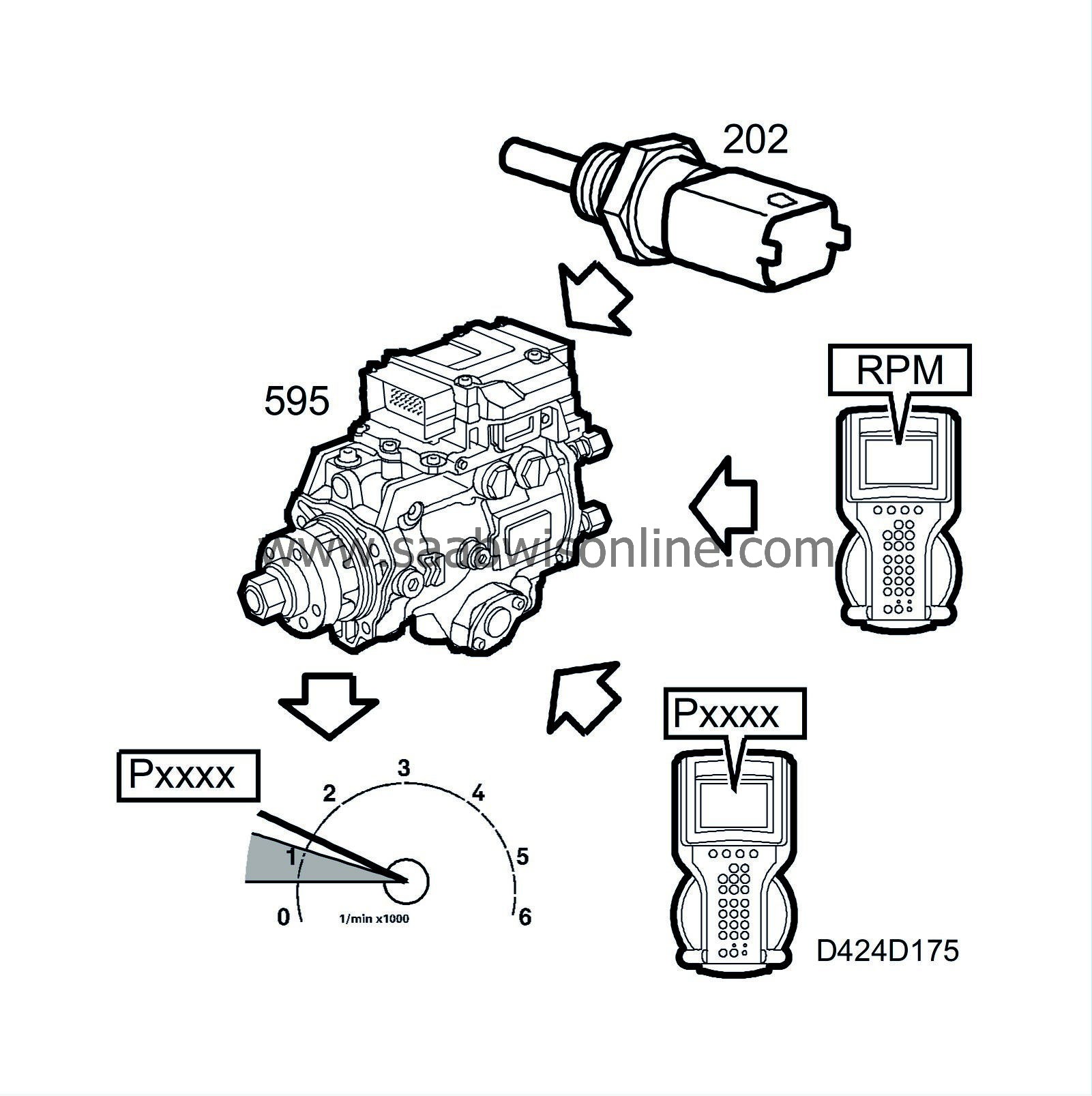
| - |
desired value, idling speed
|
|
| - |
idle speed control
|
|
Desired value, idling speed
The idling speed that is to apply is based on the engine coolant temperature, intake air temperature, whether the control module has diagnostic communication or if a system fault has occurred (DTC).Idling speed can vary from approx. 1150 rpm with a cold engine to 870 rpm with a warm engine, depending on the engine coolant temperature and intake air temperature.
Using the ACTIVATE function in the diagnostic tool, the idling speed can be temporarily raised or lowered. The idling speed can be raised to a maximum of 2000 rpm and lowered to a minimum of 700 rpm. When the ACTIVATE function is disengaged, the engine speed will return to its normal, programmed value. If a system fault should occur, the idling speed is set to 1400 rpm. The ADJUST function on the diagnostic tool can be used to program a permanent change in the idling speed of 100 rpm. If the idling speed is adjusted in this way with the diagnostic tool, the calculated idling speed is increased or decreased by the adjustment value and the total idling speed is sent on to the idling speed control.
The calculation of the desired value for the idling speed is time synchronous, i.e. the calculation is performed at determined intervals.
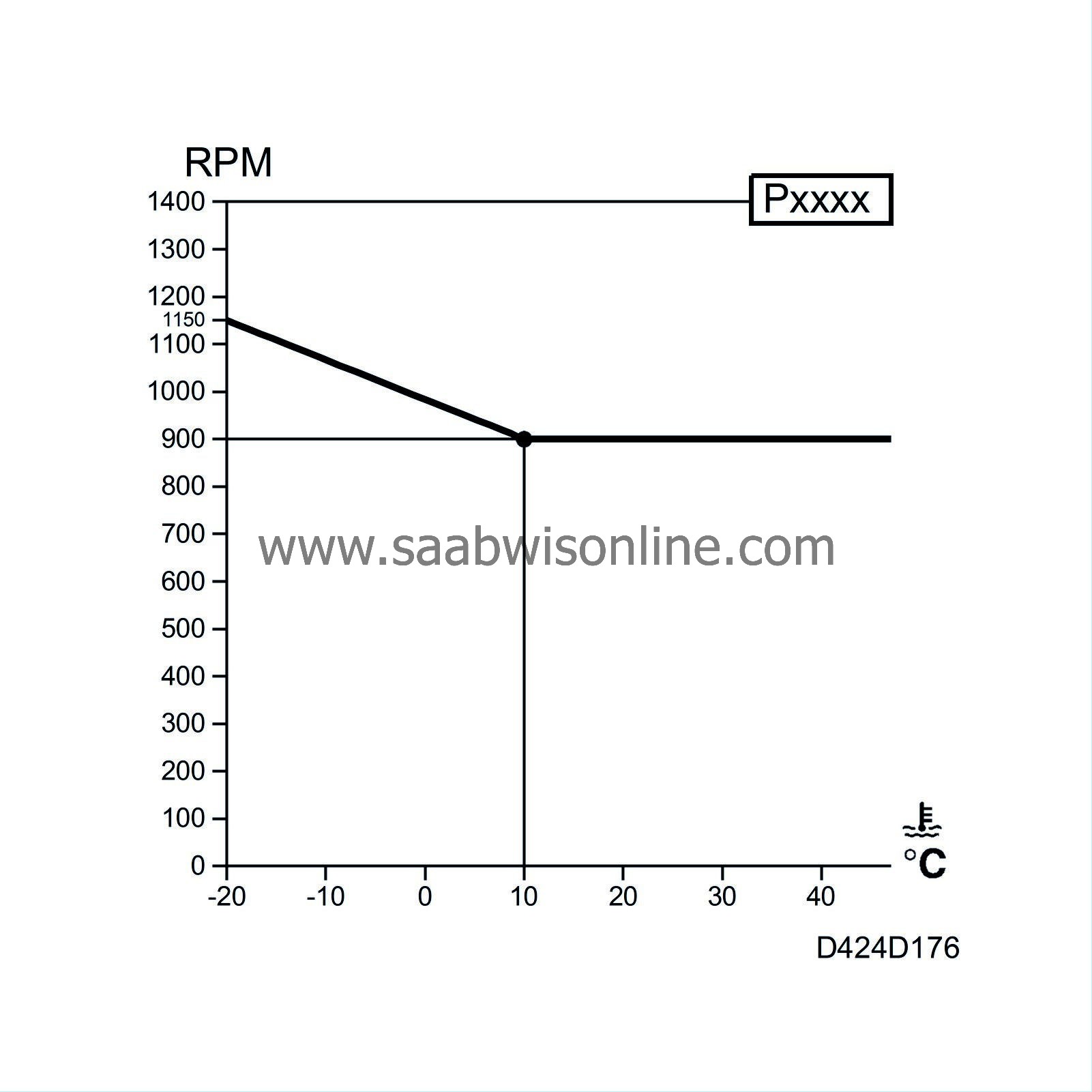
Idle speed control
The idle speed control sub-function executes the order from "desired value, idling speed".Idle speed control comprises a number of different internal calculations that are performed synchronously with the engine speed. This involves each new calculation of the fuel quantity being controlled by the engine speed. A new calculation is performed for each power stroke to determine an injection quantity that corresponds with the idling speed.
The fuel quantity from idle speed control is carried forward in the decision process in the control module.
Cylinder balancing
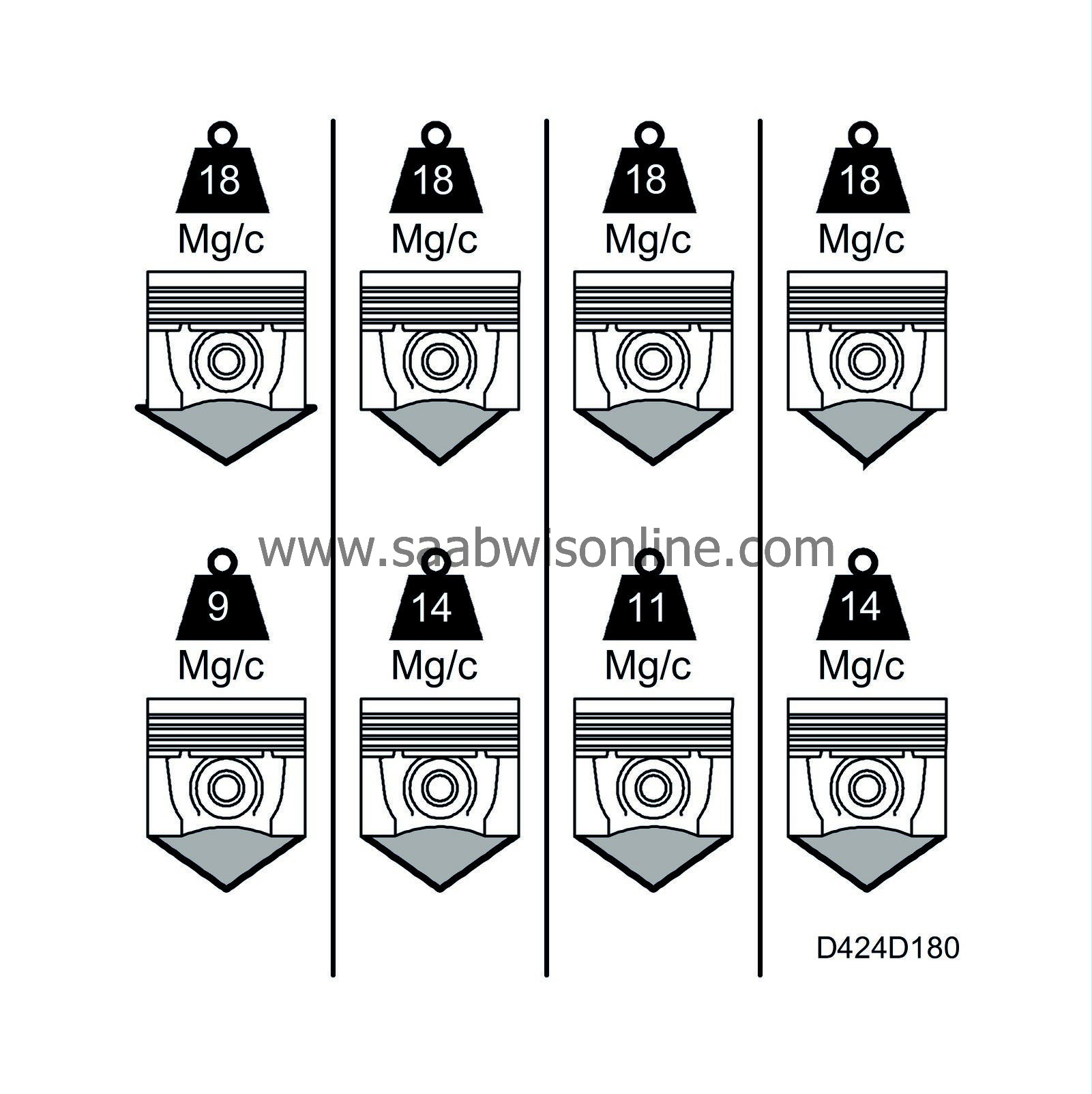
The objective of this function is to balance the combustion pulses from each cylinder. This is performed at idling speed to compensate for variations in the quantity injected into each cylinder and the differences in the efficiency of each cylinder. Compensation under other operating conditions is performed mainly for the differences in efficiency of each cylinder. This is achieved by calculating and changing the injected quantity for each cylinder individually.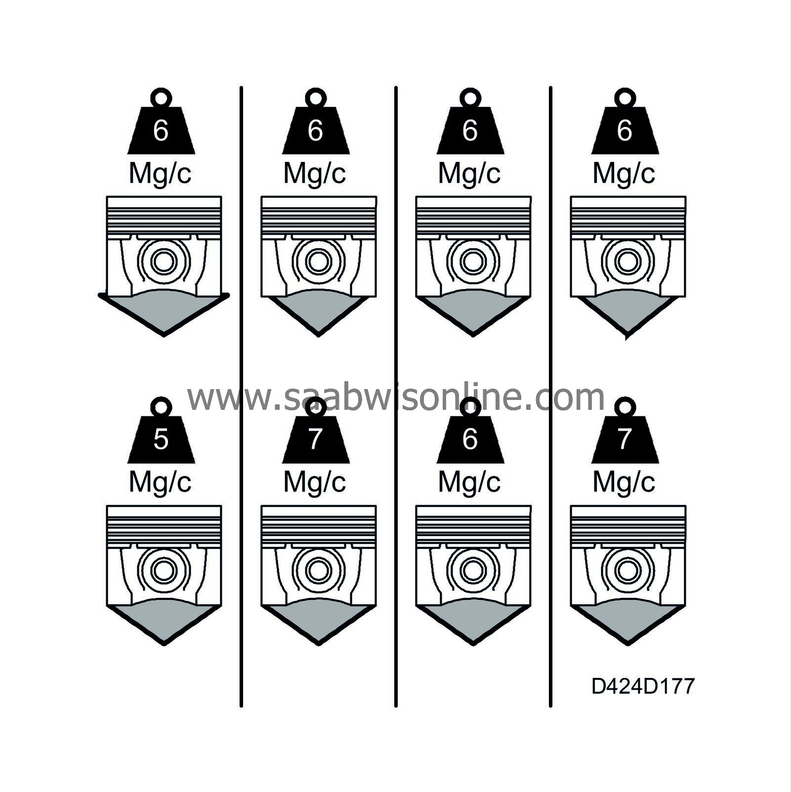
The engine control module measures the speed of the crankshaft after each power stroke. When the cylinder is about to ignite the next time, a calculation is ready to compensate the quantity for the next combustion. This compensation quantity is adapted so that the next combustion results in the same working pulse after combustion as that in the other cylinders.
The average compensation quantity for the four cylinders is adjusted towards 0% so that the idling speed is not affected by the cylinder balancing function. The limit for the range of adjustment is 5 mg/combustion.
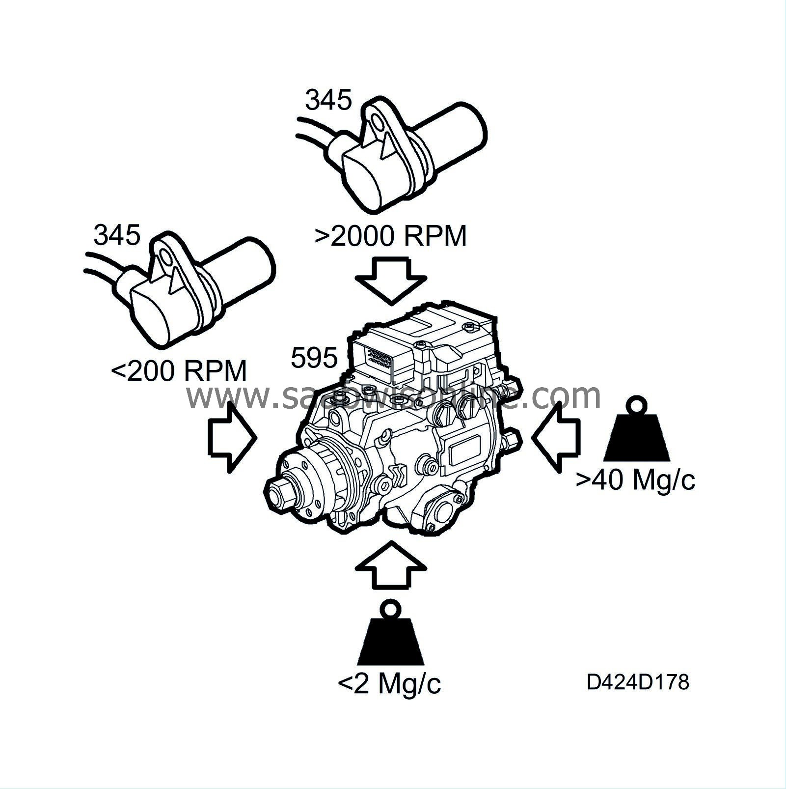
Cylinder balancing is not in operation:
| - |
under 200 rpm
|
|
| - |
over 2000 rpm
|
|
| - |
under 2 mg/combustion
|
|
| - |
over 40 mg/combustion
|
|
Calculations are performed with the following variables:

| - |
Engine speed
|
|
| - |
Injected fuel quantity
|
|
Active surge dampening
This function suppresses the engine speed variations caused by oscillations in the engine, gearbox, drive shafts and engine mountings.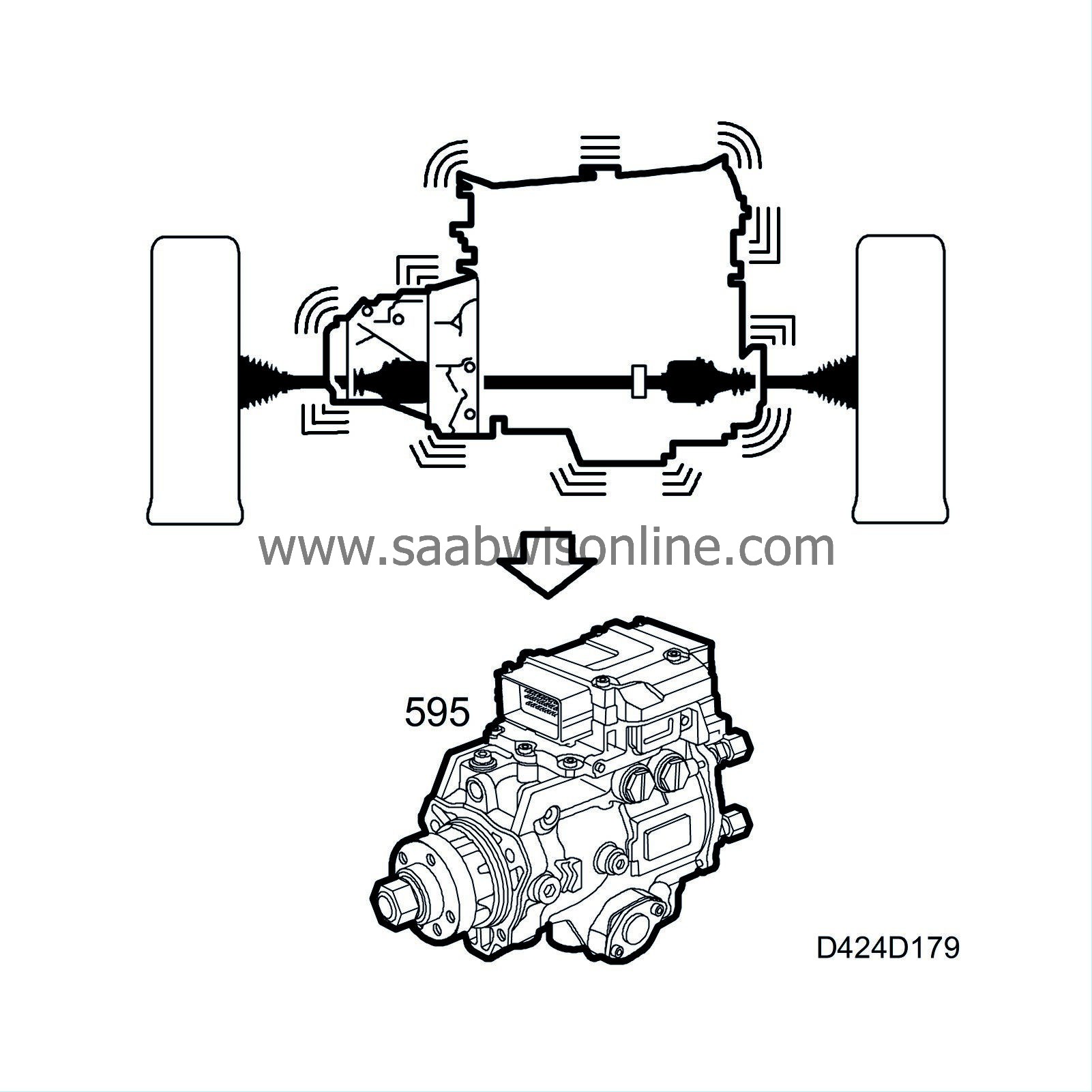
Calculations for the function are performed using the following parameters:
| - |
Engine speed
|
|
| - |
Engine speed/vehicle speed (i.e. gear position)
|
|
| - |
Fuel quantity
|
|
| - |
Clutch switch
|
|
| - |
Idle active
|
|
The result of the calculation is a correction quantity in mg/combustion for each cylinder. The limit for the range of correction is 10 mg/combustion.
The value resulting from the function is added to the value from cylinder balancing.
A/C compressor control
A/C compressor engagement is controlled by functions in DICE as well as in PSG 16. The following description covers the functions in PSG 16.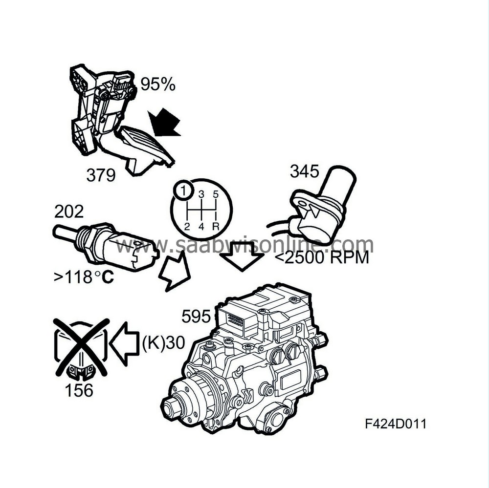
The A/C compressor function comprises two sub-functions:
| - |
Logic function
|
|
| - |
Control function
|
|
Logic function
The logic function determines when the A/C compressor should be turned off. This is performed so that the A/C compressor can be turned off under certain driving conditions when maximum engine torque must be available.The A/C compressor is turned off under the following conditions:
| - |
Coolant temperature above 123°C (253°F).
|
|
| - |
Pedal position sensor value greater than 95% and engine speed < 2000 rpm while in first gear.
|
|
Control function
The control function turns the A/C relay on and off when commanded by the logic function.When the power stage control has amplified the signal, pin K30 is grounded and the A/C relay energizes the A/C compressor solenoid clutch.
"Engine running" signal
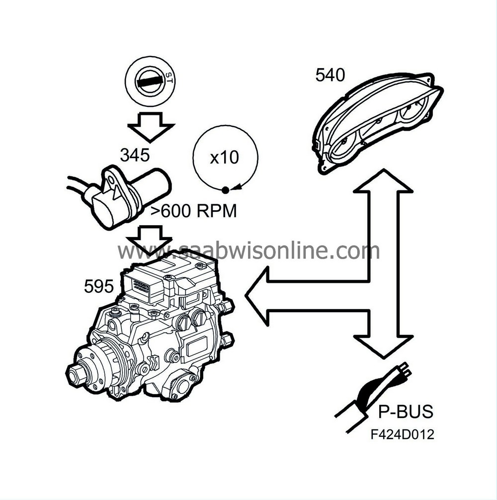
The signal is used to inform the other control modules that the engine is running. If the engine speed exceeds 600 rpm for more than 10 crankshaft revolutions, a message saying that the engine has started is sent on the P-bus.