Detailed description
| Detailed description |
The crankcase gases that are formed are first led into an oil trap built into the camshaft cover where oil is separated from the gases. The oil then runs back to the oil pan while the gases pass into the cylinders.
The crankcase ventilation system works in two different ways depending on whether there is a heavy or light load on the engine.
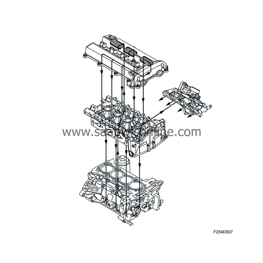
Function, light engine load
When the engine is exerted to a light load, the pressure in the engine intake manifold is relatively low and a high vacuum will prevail. Exhaust gases are led from the oil trap via a passage in the cylinder head to a non-return valve mounted in the intake manifold. From the non-return valve, the gases are led through a passage that opens into the intake manifold, where the crankcase gases are mixed with the intake air and pass into the cylinders for combustion.
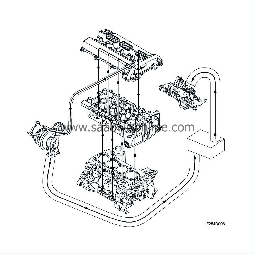
Function, heavy engine load
When the engine is exerted to a heavy load, the pressure in the intake manifold is relatively high and there is no vacuum to draw the crankcase gases into the intake manifold. The non-return valve will be closed in this case. The crankcase gases are led from the oil trap via a hose to the turbocharger inlet, where there is a vacuum. The crankcase gases are then mixed with the turbocharger inlet air and pass through the intake manifold to the cylinders.
| Evaporative emission system |
General
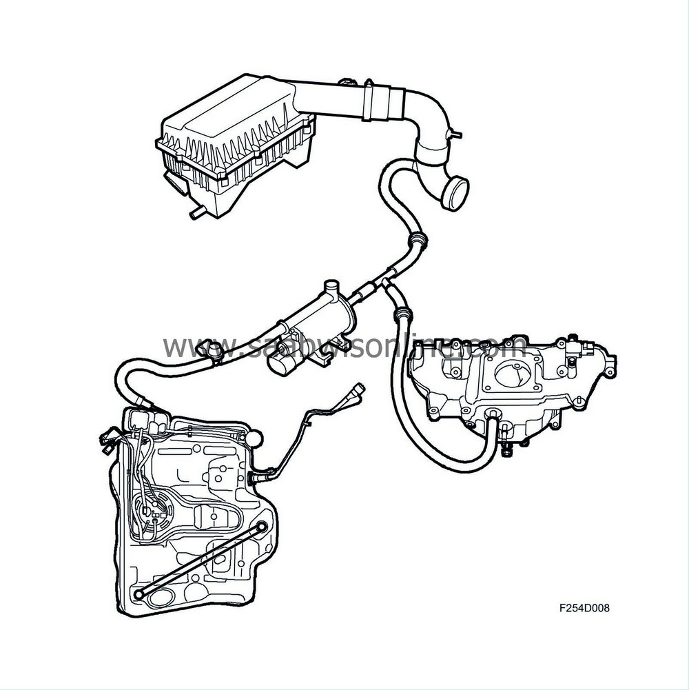
Hydrocarbons from petrol evaporation in the petrol tank are led through a pipe to an evaporative emission canister where they are stored. The fuel vapour is then drawn via the EVAP canister purge valve into the engine for combustion. The purge valve is controlled by the engine control module so that the flow it provides always constitutes a certain proportion of the total flow consumed by the engine.
For further information on the EVAP canister purge valve and its control, refer to Trionic T8.
Evaporative emission canister
the evaporative emission canister comprises a container filled with active carbon, which is used to store the fuel vapour from the tank. In the container is an inlet from the tank and an outlet to the EVAP canister purge valve as well as an opening for fresh air. Air is drawn in through this opening to the intake manifold via the active carbon.
To prevent carbon powder from penetrating the EVAP canister purge valve and causing the valve to leak, the upper part of the evaporative emission canister is fitted with a fine-mesh screen.
Purging the evaporative emission canister
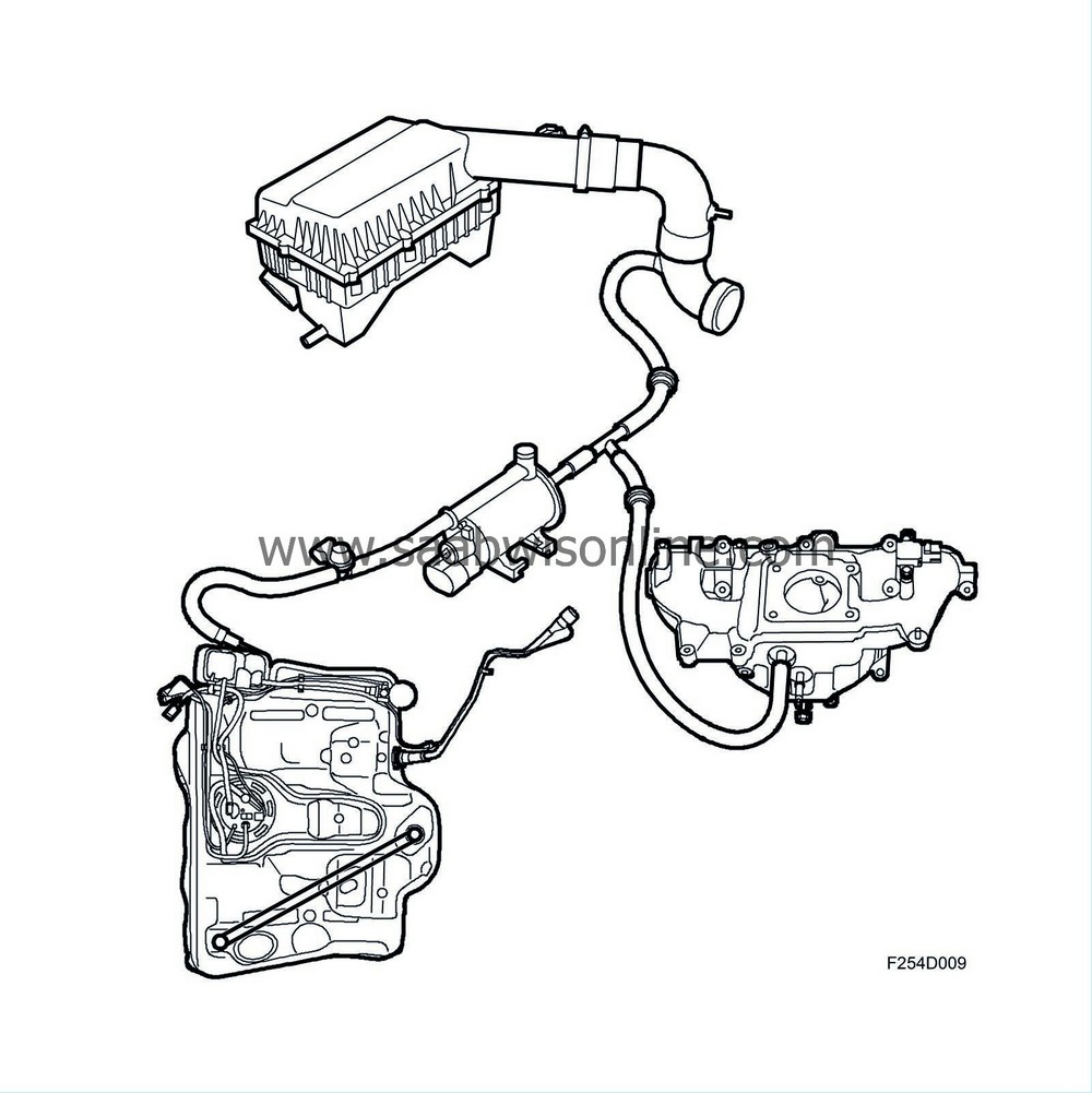
When the engine is started, surrounding air is drawn through the evaporative emission canister via the EVAP canister purge valve and a non-return valve in the intake manifold, taking it with it the fuel vapour into the engine for combustion. When the pressure in the intake manifold exceeds atmospheric pressure, another non-return valve will open to allow cleaning air to pass into the suction side of the turbocharger. To prevent the flow going in the wrong direction, there are two non-return valves included in the system.
| Catalytic converter |
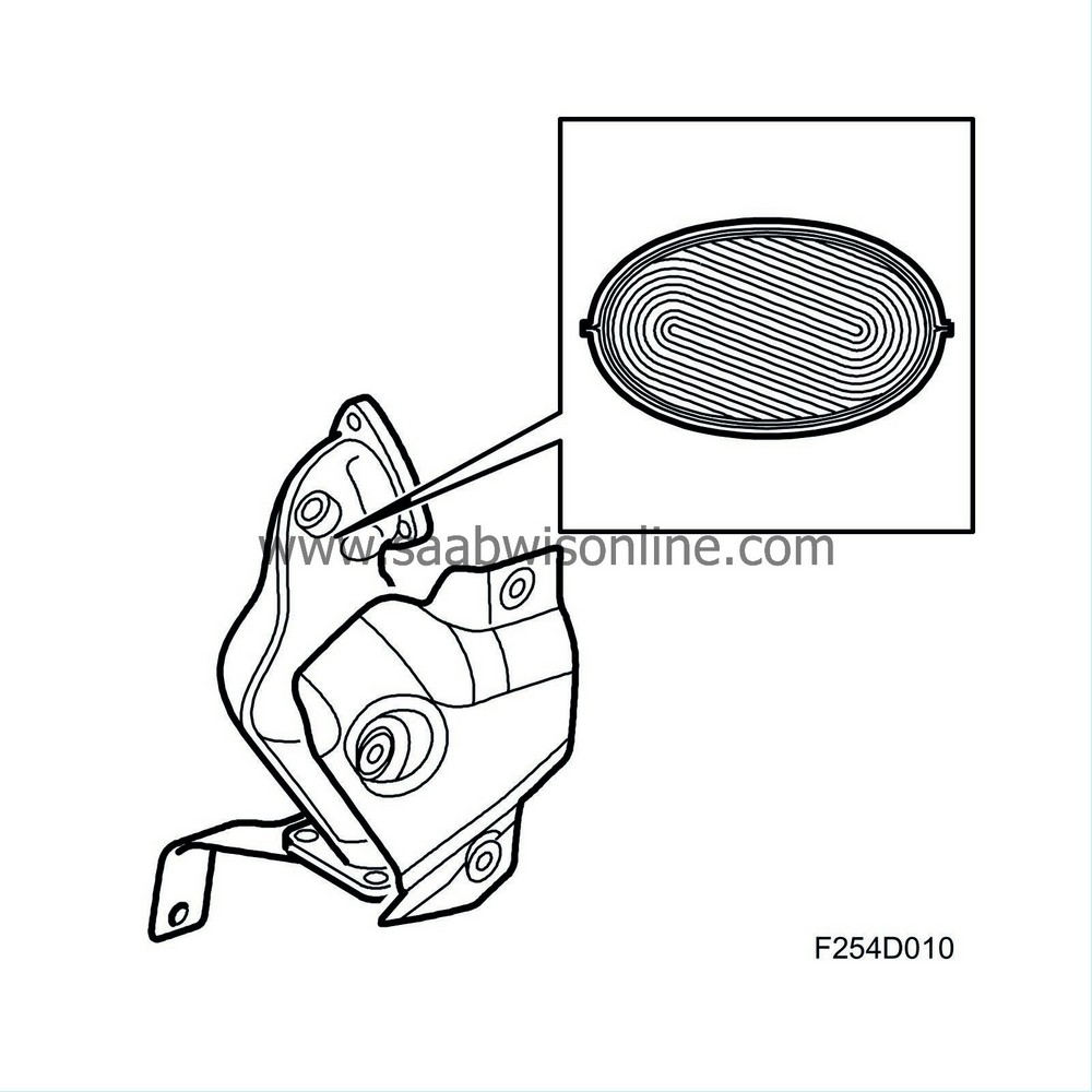
The catalytic converter comprises a ceramic carrier that is coated with a porous layer containing the catalysts rhodium and platinum.
The catalytic converter has a high conversion efficiency within a very narrow range. If the fuel-air mixture is not kept within this range, one or more gases will inevitably exceed the permitted limits. A closed loop fuel injection system ensures that the fuel-air mixture is correct.
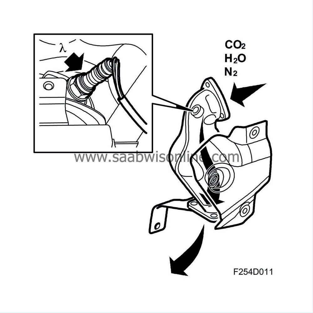
Provided the closed loop fuel injection system provides an optimal fuel-air mixture ratio, the catalytic converter reduces the nitrous oxides (NO x ) and oxidizes the carbon monoxide (CO) and hydrocarbons (HC). The end products are carbon dioxide (CO 2 ), water (H 2 O) and nitrogen (N 2 ).
In order for the catalytic converter to reduce the emissions, the car must be run on unleaded petrol only. This is because lead destroys the active components of the three-way catalytic converter.
| Secondary air system (SAI) |
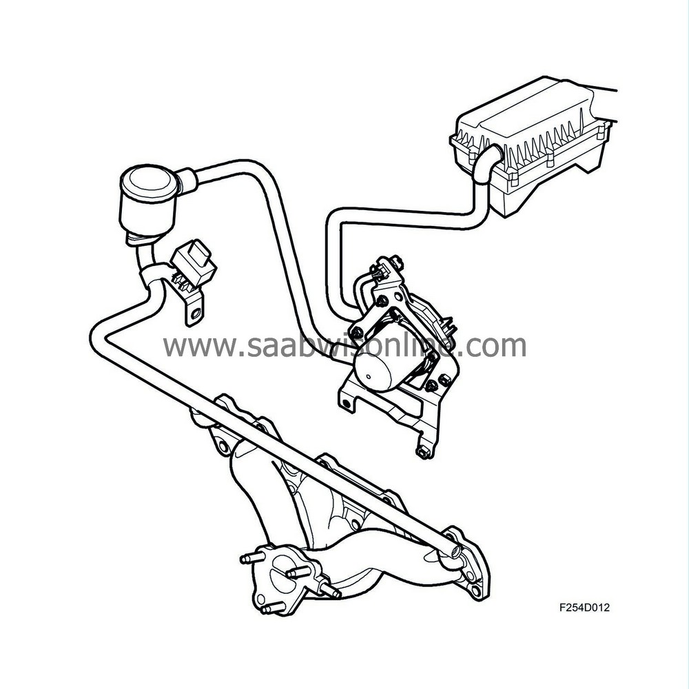
In order to get the catalytic converter to work as fast as possible after a cold start, and thereby maintain good emission values, the surrounding air is pumped into the exhaust manifold with an SAI pump (Secondary Air Injection). The oxygen in the air then initiates a chemical combustion together with the CO and HC compounds, whereby heat is generated.
More fuel is added in order to compensate for the extra air. This extra fuel is added adaptively to the calculated fuel quantity. Trionic calculates the extra amount of fuel using a matrix.
The SAI pump starts when the engine is started provided the charge air temperature and coolant temperature are within the range -11°C - +39°C and the battery voltage and air mass consumption are within limits.
Before the SAI pump starts, the engine must run for a few combustions depending on the coolant temperature and varying between 20 and 70 combustions.
The SAI pump will continue to run for another few combustions after the system has stopped requesting it. This is to avoid unnecessary hydrocarbon emissions once the SAI functions have been turned off.
To prevent exhaust gases leaking back through the SAI system, there is a non-return valve that closes when the pump stops.
| Closed loop fuel injection system |
General
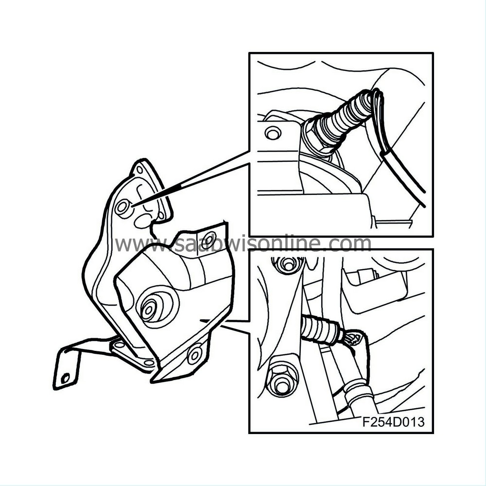
The system is electronically regulated with two oxygen sensors located in the exhaust pipe before and after the catalytic converter. The car has a catalytic converter containing a ceramic element, the walls of which are coated in the catalysts platinum and rhodium. The catalytic converter has a high conversion efficiency within a very narrow range. If the fuel-air mixture is not kept within this range, called lambda 1, one or more gases will inevitably exceed the permitted limits. A closed loop fuel injection system is necessary to ensure that the fuel-air mixture is correct.
Provided the closed loop fuel injection system provides an optimal fuel-air mixture ratio, where carbon monoxide (CO) and hydrocarbons (HC) are oxidized, the catalytic converter can also reduce the nitrous oxides (NOx). The end products are carbon dioxide (CO 2 ), water (H 2 O) and nitrogen (N 2 ). In order for the catalytic converter to reduce the emissions, the car must be run on unleaded petrol only. This is because lead destroys the active components of the three-way catalytic converter.
Oxygen sensor
The oxygen sensor consists of a primary cell with fixed electrolyte. The electrolyte is ceramic (zirconium dioxide (Z r O 2 )) and its temperature is stabilised through the addition of a small amount of yttrium oxide (Y 2 O 3 ). The electrolyte is tubular and hollow at one end.
To function properly, the catalytic converter requires an air/fuel ratio of precisely 14.7:1.
If the mixture is too weak, the oxygen content in the exhaust gases will increase. The oxygen sensor output voltage will then be about 0.1 V (lambda over 1). The engine control module reacts by extending the injection times.
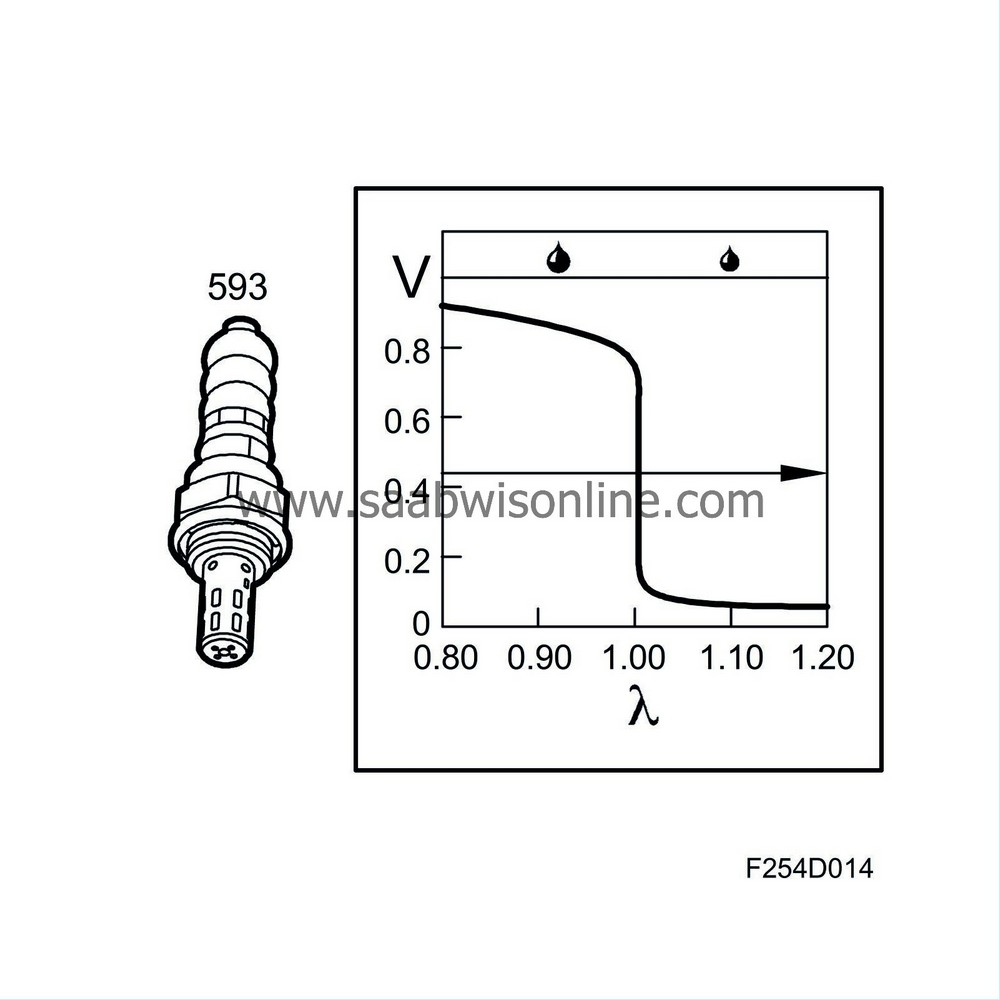
If the mixture is too rich, the oxygen sensor output voltage will be about 0.9 V (lambda under 1) and the injection pulses are shortened.
Since the working range of the oxygen sensor is between 200°C-850°C (392°F-1562°F), it is fitted with an electric preheater. Preheating is controlled by the system's control module. Under heavy loads and high rpm, the exhaust temperature is high and the preheating circuit is shut off.
For further information about the closed loop control see Group 2 “Engine control system”.


