(391-2408) Update of OnStar system, French version
|
MODIFICATION INSTRUCTION
|
|
Bulletin Nbr:
|
391-2408
|
|
Date:
...........
|
October 2003
|
|
Market:
|
CA
|
|
|
Update of OnStar system, French version
|
|
Customer Satisfaction Campaign 154 24
|
Cars in stock must be rectified before delivery.
A personal communication must be sent to the owners of cars already
delivered requesting them to get in touch with the nearest Saab garage as
soon as possible to have the fault rectified.
Saab 9-3 (9440) M03 with VIN within the interval 31026046-31045153
All cars are not affected, see separate information.
The car needs to be updated with new software, in order to improve the
functionality of the OnStar system.
The new software provides the following improvements:
|
-
|
more secure shut down of the system
|
|
-
|
longer time (48 h), that the car can be activated from OnStar
|
|
-
|
less power consumption with the ignition key in the LOCK position.
|
12 801 949 Telematic Unit (CU), French version
|
Note
|
|
In order to perform this work the following special tools are required:
|
|
-
|
PC with installed TIS 2000
|
|
-
|
Hardware lock with adapter
|
|
-
|
PC cable with RS232 adapter
|
|
-
|
Tech2 with 32 Mb card
|
|
-
|
CANdi box
|
Brief instructions
It is important that all measures are performed in the prescribed order.
ICM must be updated first because new software in ICM is required to make
it possible to carry out certain subsequent measures.
The procedure to be completed is structured according to the following
stages:
|
A.
|
Update of TIS 2000 with CD TIS 2000 2003-3 or later.
|
|
B.
|
Update of TIS 2000 2003-3 to Ed2003-3_Update3 (or later).
|
|
C.
|
Update of Tech2 software to version 107.000 or later.
|
Note
|
|
In order to save time, Tech2 should be connected to both the car and
the PC during the entire update procedure.
|
|
Important
|
|
No PC in proximity to the car:
If Tech2 disconnects
from the car, the CANdi box should be disconnected from Tech2. The CANdi box
may remain connected to the car"s data link connector.
|
|
|
|
|
D.
|
Update of car software and hardware replacement according to the
accompanying checklist (supplement D1).
|
|
A. Update of TIS 2000 with CD TIS 2000 2003-3 (or later).
|
|
Note
|
|
If the computer on which TIS 2000 is installed has already been updated
to TIS 2000 2003-3 (or later), there is no need to update the computer again.
|
|
1.
|
Insert CD TIS 2000 2003-3 (or later) into the computer.
|
|
3.
|
Follow the instructions in TIS 2000.
|
|
B. Update of TIS 2000 2003-3 to Ed2003-3_Update3 (or later)
|
Downloading software from IRIS
This section describes the download and update of TIS 2000 2003-3 to
Ed2003-3_Update3 (or later). The exe files must be run in numerical order
(starting with Ed2003-3_Update1.exe, Ed2003-3_Update2.exe and ending with
Ed2003-3_Update3.exe).
|
Important
|
|
Subsequent TIS 2003-3 updates with files later than Ed2003-3_Update3.exe
(if files are available) are possible without affecting the Service Campaign.
|
|
|
|
1.
|
Log onto international IRIS with user name and password.
|
Note
|
|
For additional information, select the help file “Ed2003-3_Update3.html",
which contains information on background as well as update instructions.
|
|
|
2.
|
In the News menu, select “TIS 2000 Ed2003-3_Update3”.
Continue by selecting “Ed2003-3_Update3.exe”, select “save
file to disk”. Save the update file anywhere in the computer and remember
its location.
|
Updating TIS2000 2003-3
|
Important
|
|
If the TIS 2000 has a client/server configuration, the update must be
started from the server on which TIS 2000 is installed.
|
|
|
|
1.
|
Start TIS 2000 and select "Help > About TIS 2000”. ”SAAB
Automobile AB edition” must be identical to the “Edition of TIS
2000 which is required for this update” described in the beginning of
this document.
|
|
2.
|
Close TIS 2000. TIS 2000 should not run when the update file is
started.
|
|
3.
|
Click on the update file saved earlier, "Ed2003-3_Update3.exe",
and do as follows after it is activated:
|
|
|
3.a.
|
Start the update file on the computer on which TIS 2000 is installed
and then wait for the “Select language” window.
|
|
|
3.b.
|
Select a language, select “Ok” and then wait for the
“TIS 2000 must be started” window.
|
|
|
3.c.
|
Select “Ok” in order to start TIS 2000 and then wait
for the ”M2269” window.
|
|
|
3.d.
|
Select “Ok” in order to start the update and then
wait for the “M723” window.
|
|
|
3.e.
|
Select “Ok” in order to confirm a completed update
and TIS 2000 will close automatically. The TIS 2000 update is complete.
|
|
C. Update of Tech2 software
|
Tech2 with new 107.000 (or later) software is required for SPS programming
and to “Add” control modules.
It is very important that Tech2 is updated to version 107.000 (or later)
before the following procedures are completed.
Follow the instructions in TIS 2000 and Tech2 in order to update the
software in Tech2.
|
D. Update of car software and hardware replacement
|
|
Important
|
|
It is extremely important that the measures are carried out in the prescribed
order.
|
|
•
|
SPS programming must not be interrupted due to a loosened diagnostics
cable or insufficient battery voltage, for example.
|
|
•
|
The car"s power consumption is high during control module programming.
Always connect a battery charger during SPS programming.
|
|
•
|
The battery charger must be able to provide 20 A. The charging
voltage for the battery charger may not exceed 16 V as the electronics in
the car may be damaged.
|
|
•
|
Do not activate any switches in the car e.g. opening/closing doors
or windows, etc. Programming could be interrupted and the control module could
be damaged to such an extent that it is no longer functional.
|
|
•
|
During SPS programming, all normal bus communication is stopped.
As a result, the main fuse boxes assume Limp Home mode and switch on the dipped
beams and rear lighting.
|
|
|
Initial procedure
The entire procedure is indicated on the checklist (Supplement D1),
which can be used as a guide during the entire process. One copy of the checklist
should be printed out for each car receiving an update.
|
Note
|
|
Enter the car"s VIN and equipment level in the table header of the checklist
(supplement D1) before proceeding. This facilitates work and saves time. So
that the correct alternative can be chosen when “Add” is executed,
check in SID whether there are menu options for parking and engine block heaters.
|
|
Important
|
|
Cars in transport mode:
Fit the transport
fuse (60A maxi fuse) in position F37 in the fuse box in the engine bay (UEC).
|
|
|
|
1.
|
Remove fuse 23 (40A maxi fuse) from the dashboard fuse box.
|
|
2.
|
Connect the battery charger to the car battery.
|
|
3.
|
Connect Tech2 to the car"s data link connector and to a PC with
TIS 2000.
|
|
4.
|
Get Security Access to Tech2 from the
car.
|
SPS programming of ICM
|
1.
|
Request data from ICM using Tech2.
|
|
2.
|
Download the SPS program from TIS 2000 to Tech2.
|
|
3.
|
Download security access from TIS 2000 to Tech2.
|
No special procedures are required during the programming phase. Follow
the instructions in TIS 2000 and Tech2 for SPS. Programming will stop for
a few seconds at 0.9%; this is normal.
|
Important
|
|
If programming fails and the control module is in "boot mode", follow
these instructions:
|
|
1.
|
Turn the ignition key to the "START" position.
|
|
2.
|
Remove fuse F2 from the dashboard fuse box.
|
|
3.
|
Program the control module. Ignore the message "switch off/on
ignition" during the programming phase.
|
|
4.
|
Fit fuse F2 after successful programming.
|
|
5.
|
Turn the ignition key to "OFF".
|
|
|
"Add" ICM
For help in selecting the correct option, see the help information in
supplement D2. Several of the car"s control modules are married when “Add”
is executed for this control module.
|
Note
|
|
Tech2 can sometimes lose contact with MIU (Main Instrument Unit). If
this is the case, press "Exit" twice and restart "Add".
|
If Tech2 receives a “negative response” from AMP1, do as
follows:
|
1.
|
Turn the ignition key to the "LOCK" position.
|
|
2.
|
Remove fuse F14 from the dashboard fuse box.
|
Replacing the Communication Unit (CU)
Replace the Communication Unit (CU). See Supplement D3 “Replacing
the Communication Unit (CU)”.
"Add" CU
For help in selecting the correct option when "adding" the unit, see
the help information in supplement D2. Several of the car"s control modules
are married when “Add” is executed for this control module.
|
E. Final procedure and functionality check
|
|
1.
|
Disconnect the battery charger from the car.
|
|
2.
|
Fit fuse 23 into the dashboard fuse box.
|
|
3.
|
Check the time and date in SID; adjust if necessary.
|
|
4.
|
Erase all diagnostic trouble codes using Tech2.
|
|
5.
|
Read diagnostic trouble codes to ensure that no faults remain.
|
|
6.
|
Disconnect Tech2 from the car"s data link connector.
|
|
7.
|
Check the functionality of the OnStar system in accordance with
the following (7.a - 7.c):
|
|
|
7.a.
|
Activate the audio system
by pressing the
ICM unit (infotainment system control panel) ON button
. Verify radio
sound in the speaker system.
|
|
|
7.b.
|
Dealer-stock cars:
Press the blue “OnStar Services button”
to start the audible OnStar demo message. During the message,
press the blue “OnStar Services button” again
to connect to the OnStar Call Center. Explain to the advisor that
you are testing the OnStar software update, and ask the advisor to verify
the location of the car.
Cars returned by customers:
Press the blue “OnStar Services button”
to connect to the OnStar Call Center. Explain to the advisor that
you are testing the OnStar software update, and ask the advisor to verify
the location of the car.
|
Note
|
|
Step 7.b may take a few moments while the car’s on-board telephone
module connects to the local cellular network.
|
|
|
|
7.c.
|
After the Call Center advisor has verified the location of the
car, end the call by
pressing the "White dot button"
.
|
|
8.
|
If the OnStar Call Center is not reached within 10 minutes, call
Saab technical support in Canada for further assistance.
|
|
9.
|
Cars with pinch protection:
Set pinch
protection for the window lifts.
|
|
10.
|
If the car is to be reset to transport mode:
Remove the transport fuse F37 (60A maxi fuse) from the fuse box in
the engine bay (UEC).
|
|
Time/Warranty information
|
See separate information.
|
|
|
|
|
|
|
|
|
|
|
|
|
|
|
|
|
|
|
VIN
|
|
|
|
|
Customer car
|
|
|
Dealer stock car
|
|
|
Date
|
|
|
|
|
|
|
|
|
|
|
|
|
|
|
|
|
|
|
|
|
|
|
|
|
|
|
|
|
|
|
Parking Assistance
|
|
|
Parking Heater
|
|
|
|
|
Rear CD-Changer
|
|
|
Block heater, Time Relay
|
|
|
|
|
|
|
|
|
|
|
|
|
Unit
|
Procedure
|
Info
|
Notes
|
OK/NOK
|
|
1
|
|
Fill in the checklist header
|
|
|
|
|
2
|
UEC
|
Fit the transport fuse (60A maxi fuse) in position F37 in the fuse box
in the engine bay (UEC).
|
Only affects cars in transport mode
|
|
|
|
3
|
Dashboard fuse box
|
Remove fuse 23 (ventilation fan)
|
|
|
|
|
4
|
Battery
|
Connect battery charger
|
|
|
|
|
5
|
Tech2
|
Connect Tech2.
|
|
|
|
|
6
|
Tech2
|
Get Security Access from car
|
|
|
|
|
7
|
ICM
|
Request data
|
|
|
|
|
8
|
TIS 2000 (ICM)
|
Download SPS program from TIS 2000 to Tech2
|
|
|
|
|
9
|
TIS 2000
|
Download security access from TIS 2000 to Tech2
|
|
|
|
|
10
|
ICM
|
SPS programming (approx. 7 min.)
|
|
|
|
|
11
|
ICM
|
Add
|
|
*1, *2
See supplement D2
|
|
|
12
|
CU
|
Replace the Communication Unit (CU)
|
|
|
|
|
13
|
Tech2
|
Get Security Access from car
|
|
|
|
|
14
|
TIS 2000
|
Download security access from TIS 2000 to Tech2
|
|
|
|
|
15
|
CU
|
Add
|
|
See supplement D2
|
|
|
16
|
Battery
|
Disconnect battery charger
|
|
|
|
|
17
|
Dashboard fuse box
|
Fit fuse 23 (ventilation fan)
|
|
|
|
|
18
|
SID
|
Check time and date; adjust as necessary.
|
|
|
|
|
19
|
Tech2
|
Erase all diagnostic trouble codes.
|
|
|
|
|
20
|
Tech2
|
Read diagnostic trouble codes
|
|
|
|
|
21
|
Tech2
|
Disconnect Tech2
|
|
|
|
|
22
|
OnStar
|
Check the functionality of the OnStar system
|
|
See item 7 in page 4.
|
|
|
23
|
Door control module
|
Set pinch protection
|
Only affects cars with pinch protection
|
|
|
|
24
|
UEC
|
Remove the transport fuse F37 (60A maxi fuse) from the fuse box in the
engine bay (UEC).
|
If the car is to be reset to transport
mode
|
|
|
|
Notes
|
Description
|
Procedure
|
|
*1
|
Lost communication with MIU.
|
Press "EXIT" twice and restart "Add" program
|
|
*2
|
"Negative Response" from AMP1.
|
Turn off ignition. Remove fuse 14 from the dashboard fuse box, wait
10 seconds and refit the fuse. Press "EXIT" twice and restart "Add" program.
|
ICM
|
Selection
|
Help information
|
|
Steering Wheel Position
|
Select “Left”.
|
|
Engine Fuel Type
|
Select “Petrol”.
|
|
Air Condition Control
|
MCC is manually controlled climate control. The panel has no display.
ACC is automatically controlled climate control. The panel has a display.
|
|
Parking Assistance
|
Four sensors are mounted in rear bumper if equipped with SPA.
|
|
Parking Heater
|
Select the correct response. Check the note in the checklist header.
|
|
Rain Sensor
|
Rain sensor is mounted on windscreen at rear-view mirror.
|
|
Theft Alarm
|
All vehicles with theft alarm have a tilt/movement detector mounted
in the overhead console. Detectors are visible through the two grilles in
roof console.
|
|
Trip Computer
|
Check if more than four trip computer functions can be displayed on
SID. If so, the vehicle is equipped with trip computer.
|
|
Seat Heater
|
Check for buttons on climate control panel.
|
|
Seat Ventilation
|
Select "
Without".
|
|
Block heater, Time Relay
|
Select the correct response. Check the note in the checklist header.
|
|
Telephone
|
Select "
OnStar/
Telematics
".
|
|
Telephone Type
|
Select "
AMPS".
|
|
Rear CD-Changer
|
Select the correct response. Check in the compartment on the left rear
in the trunk.
|
|
CD player in dash
|
CDF (CD Front) is a panel-mounted CD Player for one disc. The player
has an Eject button only on the panel.
CDCF (CD Changer Front) is a panel-mounted CD changer for six discs.
The changer has one button for each disc on the panel.
|
|
Navigation System
|
Select "
Without".
|
|
Radio Type
|
Select the correct response.
|
|
Country setting
|
Select the correct response.
|
|
Market
|
Select the correct response.
|
|
Language Selection
|
These languages are supported by control module software. Select language
to be displayed on SID (and ICM if equipped with display).
|
|
Tech2 suggests values for next scheduled service.
|
Check that the next scheduled service value is correct, change if necessary
(see table below).
Enter the number of
Days Since
Intermed. Service
. Count the number of days since the intermediate
service, see “Warranty and Service Record booklet”. If the car
has not yet been serviced, count the number of days since the Delivery Service.
Note that the value is set to 999 when the ICM is SPS programmed.
|
Example of service screen in Tech2
|
Next Main Service
|
|
029832 Miles
|
|
Next Intermediate Service
|
|
014379 Miles
|
|
Days SINCE Intermed. Service
|
|
999
Days
|
|
Next Main Serv. Occasion
|
|
1
|
Service interval (ICM)
|
1st Main service (km)
|
48 000
|
|
2nd Main service (km)
|
96 000
|
|
Intermediate Service (km)
|
23 136
|
CU
|
Selection
|
Help information
|
|
Telephone
|
Select "
OnStar/
Telematics
".
|
Replacing the Communication Unit (CU)
|
Important
|
|
Handle the fibre optic cables with care or the signal may be distorted.
|
|
•
|
It is very important that the two leads in the connector are not
confused with one another.
|
|
•
|
Do not splice the cables.
|
|
•
|
Do not bend the cable in a radius smaller than 25 mm.
|
|
•
|
Do not expose the cable to temperatures exceeding 85
°
C.
|
|
•
|
Keep the cable ends free from dirt and grime.
|
|
•
|
Do not expose the cable to impact as this may cause the transparent
plastic to whiten, thereby reducing the intensity of the light and causing
possible communication interruptions.
|
|
•
|
The cable should not lie against any sharp edges as this may cause
increased signal reduction.
|
|
|
 Warning
|
|
The visible red light is laser class 1. Do not look directly into the
optical fibre or the control module connector at a close distance. Distances
of less than 20 m between eye and light source can result in damage to the
eye.
|
|
|
|
|
|
|
1.
|
Fold down the back rest in the rear seat.
|
|
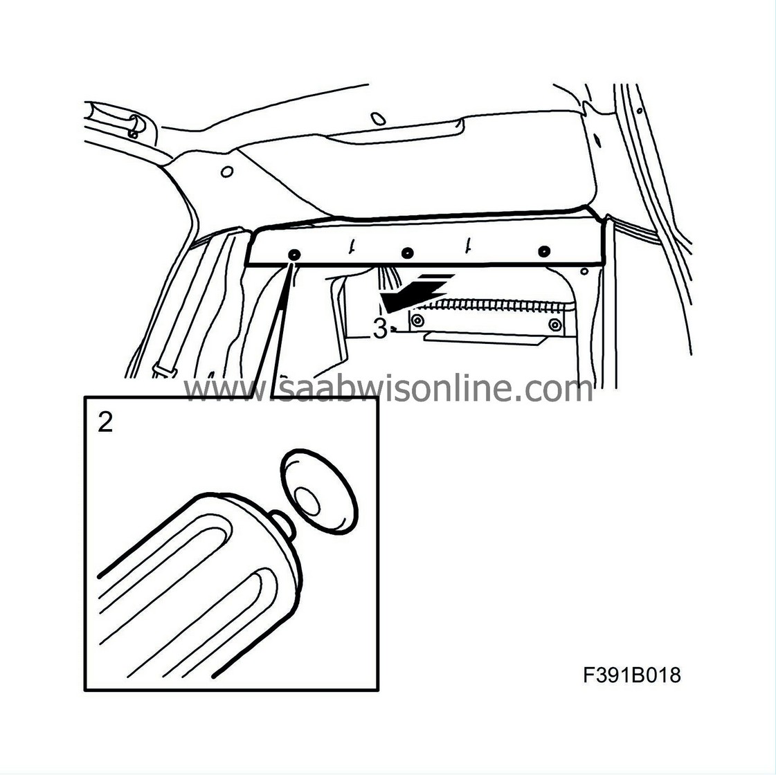
2.
|
Remove the clips holding the parcel shelf trim.
|
|
3.
|
Draw the parcel shelf trim straight out forwards.
|
|
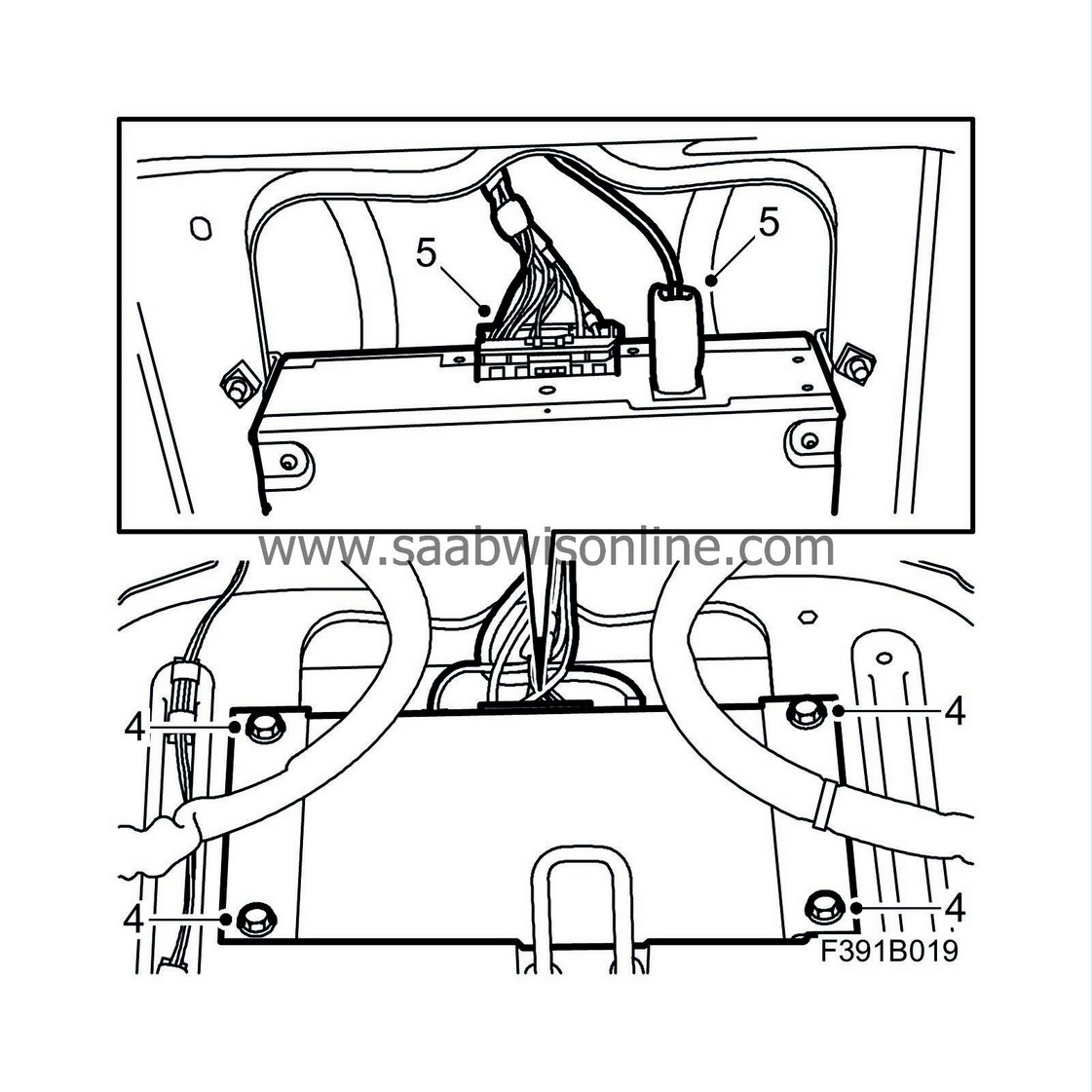
4.
|
Remove the screws.
|
Important
|
|
ESD-SENSITIVE COMPONENT
|
|
Ground yourself by touching the car body before removing/connecting
the component"s contact.
Do not touch the component"s pins
.
|
|
When the control module is replaced
|
|
• Keep the new control module in its packaging as long as possible.
|
|
• Deposit the replaced control module in the returns packaging
without touching its pins.
|
|
|
|
|
6.
|
Lift out the communication unit.
|
|
7.
|
Set the new communication unit in the correct position.
|
|
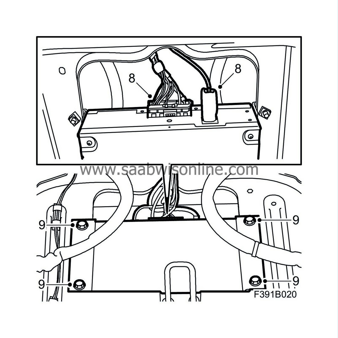
8.
|
Connect the connector.
|
|
10.
|
Slide in the parcel shelf trim. Make sure the lugs fully engage
the mountings in the parcel shelf plate.
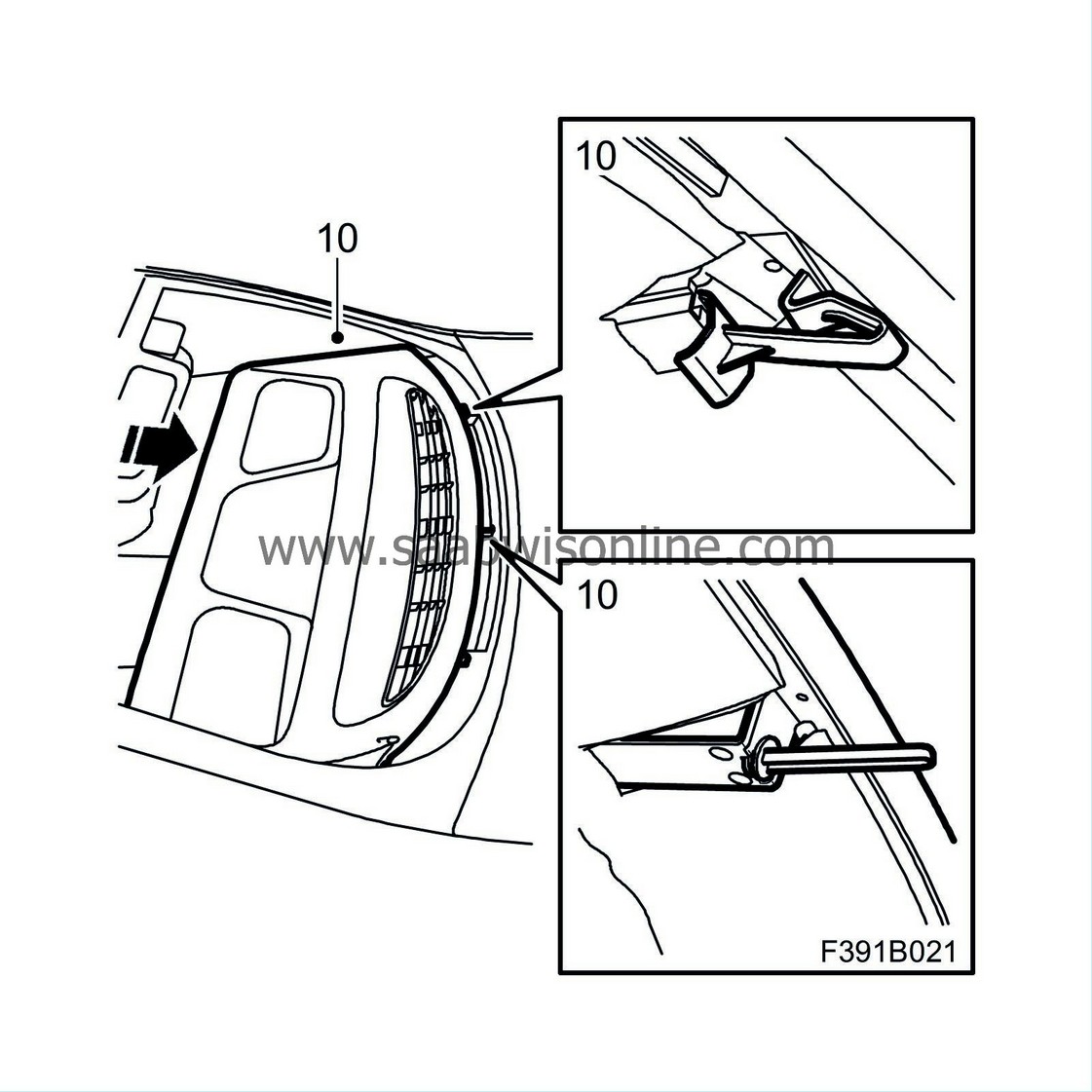
|
|
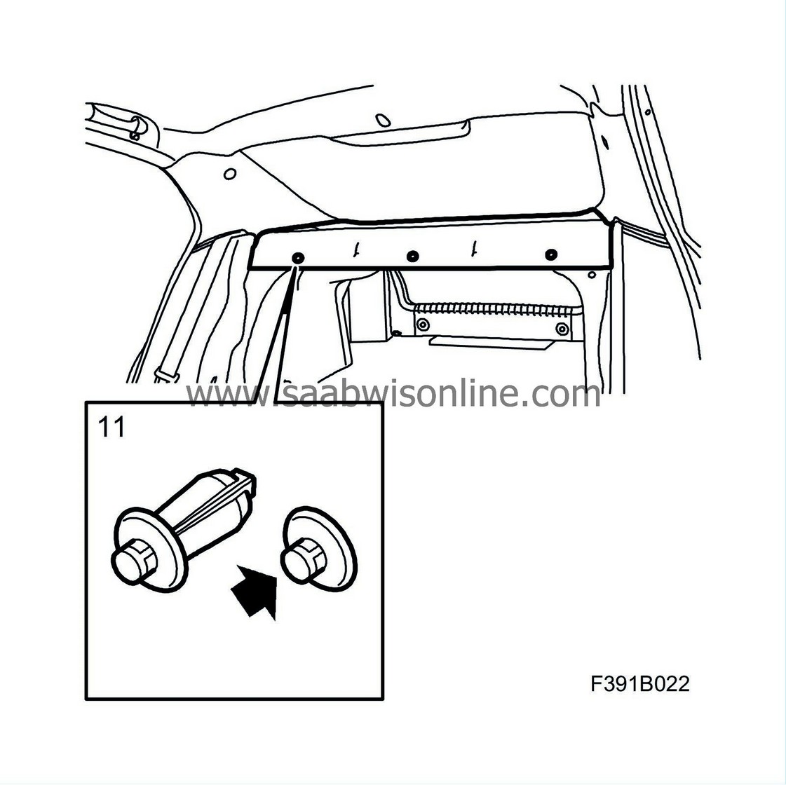
11.
|
Fit the clips to the parcel shelf trim.
|
|
12.
|
Fold up the back rest. Check that the back rest is locked.
|


 Warning


