Mass air flow sensor (205), diesel
|
|
Mass air flow sensor (205), diesel
|
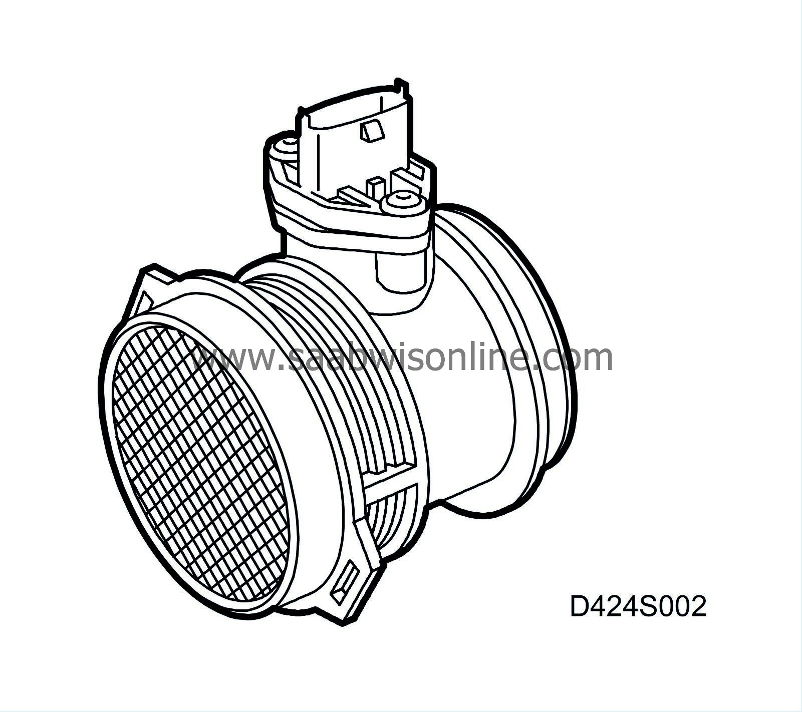
Mass air flow sensor (205)
The task of the mass air flow sensor is to continually measure the airmass consumed by the engine during operation.
The sensor consists of two main components; a connection pipe and a sensor
Measurement is as follows. Part of the air flow of the mass air flow sensor is guided past a measurement plate. This measurement plate is made up of a thin semi-conductor membrane. A heating element and a number of temperature sensors sit on the membrane. The heating element contains a resistor that gives off heat when supplied power. In addition to the resistor, there is a temperature sensor that allows for exact control of heat development in the heating element. The temperature of the heating element is controlled based on the temperature of the incoming air. Two additional temperature sensors sit on the membrane, one upstream and one downstream from the heating element (as seen from the direction of air flow). If no air flows past the membrane, the temperature over the entire surface of the membrane will be the same. The two temperature sensors, up and downstream from the heating element, will then detect the same temperature.
When air begins to flow through the mass air flow sensor, the membrane cools upstream from the heating element. This is detected by the temperature sensor on the membrane. Downstream from the heating element, the membrane and temperature sensor will be as warm as before the air started to flow. By measuring the temperature difference between the two sensors (up and downstream) in the air flow, airmass can be calculated. The direction of flow can also be determined by considering which of the two temperature sensors is warmer and cooler, respectively. All necessary calculations are performed in the mass air flow sensor. The signal, which is available to the engine control module, is the calculated airmass and the temperature of the incoming air.

|
Pin No.
|
Signal type
|
Description
|
|
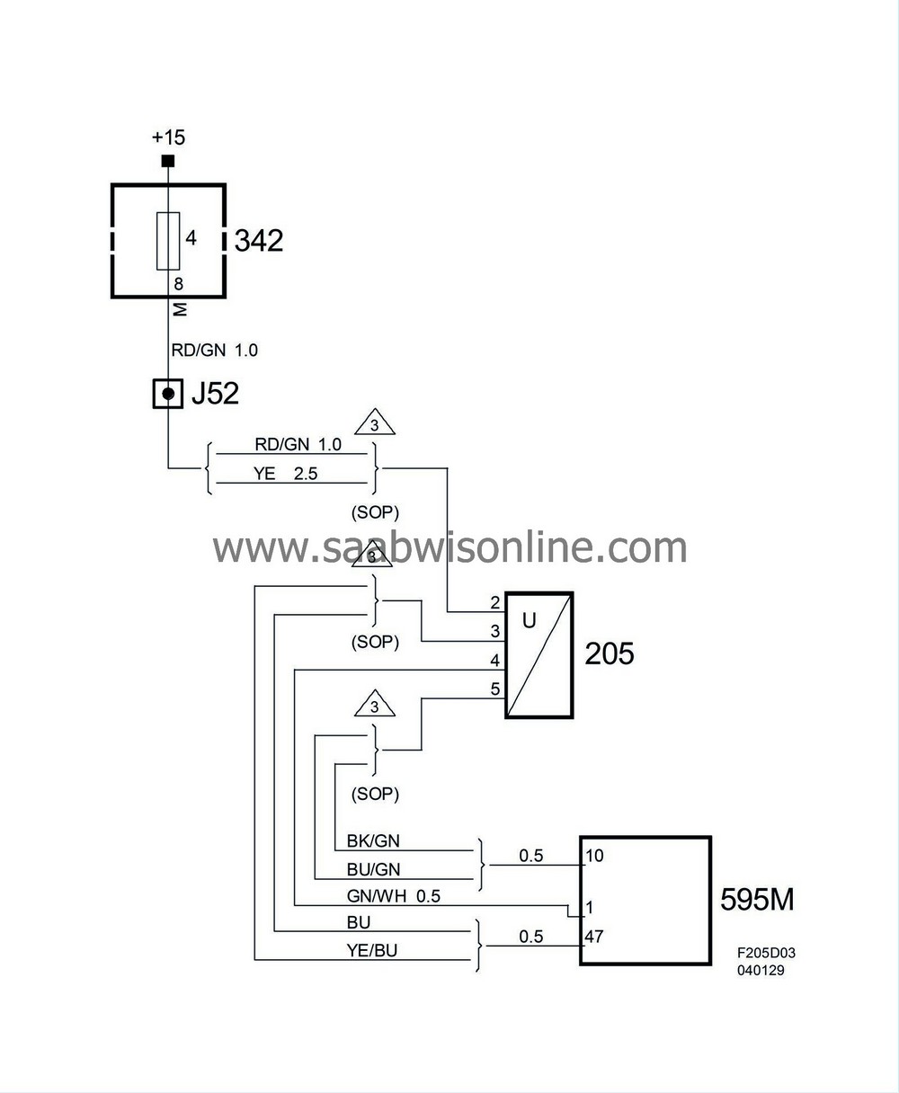
2
|
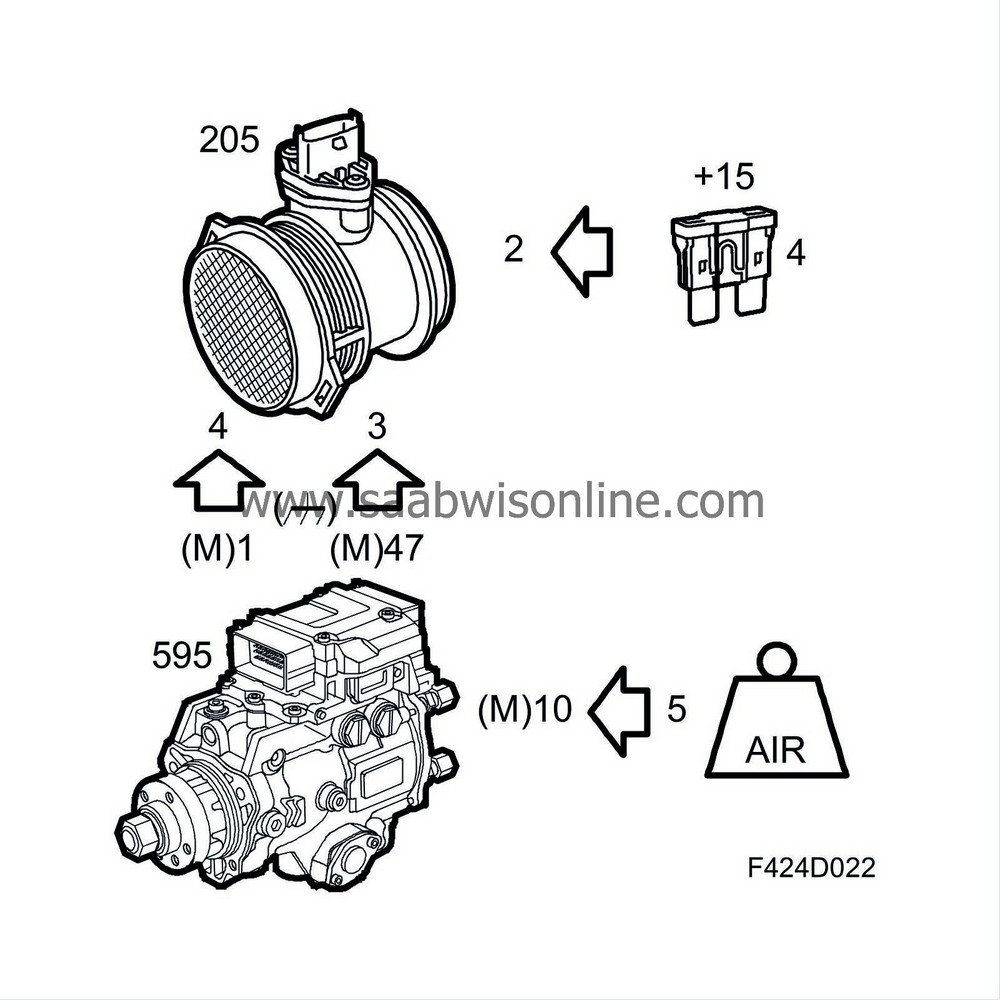
Power supply, +15
|
Sensor's voltage supply via fuse 4.
|
|
3
|
Ground
|
Sensor's ground. Connected to ECM pin 47(M)
|
|
4
|
MAF+
|
|
|
5
|
Signal
|
Sensor's output to ECM pin 10(M).
|


