SID (541)
| SID (541) |
| Location |
SID (541)
| Principal use |
SID displays information on the following vehicle functions to the driver and passenger:
| • |
Trip computer information and settings
|
|
| • |
Warning & indicator messages
|
|
| • |
Time and date
|
|
| • |
Outside temperature (from BCM)
|
|
| • |
Navigation symbols (direction arrows, etc, only on ICM 3)
|
|
| • |
Radio and CD information
|
|
| • |
Service messages
|
|
| • |
Telephone information (symbols and text messages)
|
|
| • |
Customer settings
|
|
| • |
Alarm indicator (if alarm fitted), LED on back of SID
|
|
SID measures the light intensity from the front for the interior lightning.
SID stores all the characters and symbols that are used and shown on SID. The information shown by SID is controlled and governed by ICM.
| Type |
SID has an 18.5 cm wide and 3.5 cm high LCD (Liquid Crystal Display) screen.
An NTC resistor is mounted on the LCD glass to measure its temperature.
On the back of SID is a light sensor (photo diode) that measures the backlight (1-40000 lux) and an alarm diode to indicate that the alarm is armed (state/mode). A light conductor leads the light from the cover to and from the two diodes.
SID has a microprocessor and a ROM to store symbols and characters.
SID has a 12-pin connector.
| Connection |

|
Pin no.
|
Signal type
|
Description
|
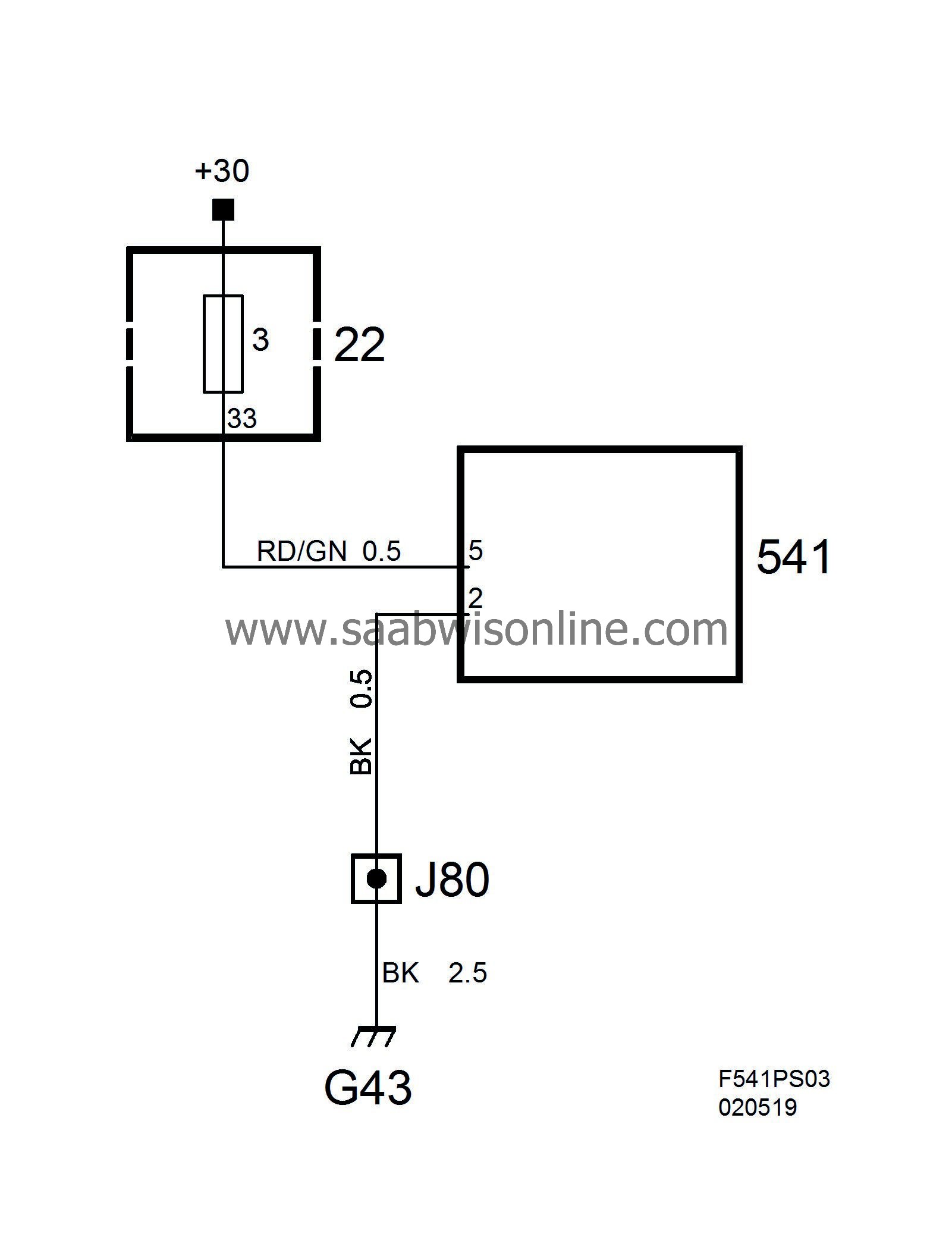
| 2 | Ground | Grounding point G43 |
| 3 | Wake-up signal | Wake-up lead from ICM pin 9. |
| 5 | +30 supply | From instrument panel main fuse box (22) pin 14 via fuse 14. |
| 6 | Signal input, alarm indicator light | If an alarm is fitted, pin 6 will be connected and alarm status will be indicated by the LED on SID. |
| 9 | Communication cable, bus (+) | Lead to ICM pin 8. |
| 10 | Communication cable, bus (-) | Lead to ICM pin 7. |
Power supply and ground

Signal input, alarm indicator light

Communication cables to ICM

The lead for the wake-up signal is connected to pin 5 from ICM pin 9. ICM supplies the lead with 5V when SID is OFF and grounds the lead when SID is to be changed to ON.


