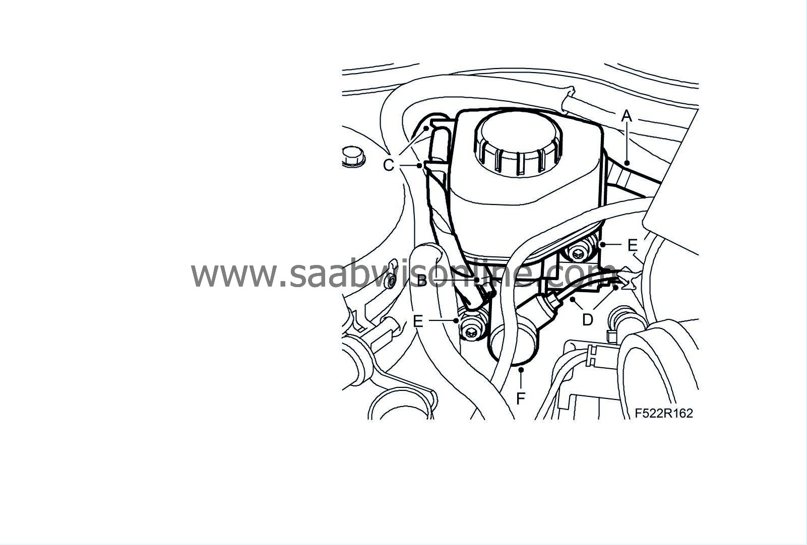
Level sensor, brake fluid reservoir, RHD
|
|
Level sensor, brake fluid reservoir, RHD
|
|
Important
|
|
Scrupulous cleanliness must always be observed during all work with hydraulic components.
|
|
|
|
1.
|
Fit the wing cover onto the right-hand front wing.
|
|
2.
|
Lay a rag under the brake fluid reservoir.
|
|
3.
|
Remove the brake fluid reservoir cap.
|
|
4.
|
Drain the brake fluid reservoir's brake chamber:
|
|
|
•
|
Connect the
brake bleeder
(A) to the air nipple on the brake caliper for the left-hand front wheel.

|
|
|
•
|
Open the nipple and draw out brake fluid until one of the reservoir chambers is empty.
|
|
|
•
|
Close the nipple and disconnect the brake bleeder.
Tightening torque for air nipple: 16 Nm (12 lbf ft)
|
|
|
•
|
Connect the brake bleeder to the air nipple on the front right wheel.
|
|
|
•
|
Open the nipple and draw out brake fluid until the other reservoir chamber is empty.
|
|
|
•
|
Close the nipple and disconnect the brake bleeder.
Tightening torque for air nipple: 16 Nm (12 lbf ft)
|
|
5.
|
Remove the brake fluid reservoir:
|
|
|
•
|
Manual gearbox:
Detach the hose (A) for the clutch from the brake fluid reservoir. Collect any brake fluid that runs out.

|
|
|
•
|
B207:
Remove the cover for the air cleaner.
|
|
|
•
|
D223L:
Remove the intake hose.
|
|
|
•
|
Unplug the connector (B) for the brake fluid reservoir level sensor and the cable from the clips (C) on the reservoir.
|
|
|
•
|
Remove the brake pipes (D) from the master cylinder.
|
|
|
•
|
Remove the nuts (E) securing the master cylinder to the brake servo.
|
|
|
•
|
Remove the master cylinder (F).
|
|
|
•
|
Remove the locking bolt from the brake fluid reservoir and detach the reservoir from the cylinder.
|
|
|
•
|
Remove the level sensor from the brake fluid reservoir.
|
|
Important
|
|
The EHPS system must not be run dry. Do not reuse drained fluid. Fill the hydraulic system with special fluid.
|
|
|
|
1.
|
Fit the brake fluid reservoir and components:
|
|
|
•
|
Fit the level sensor to the brake fluid reservoir.
|
|
|
•
|
Fit the brake fluid reservoir onto the master cylinder (F) and tighten the screw.

|
|
|
•
|
Fit the master cylinder (E). Apply threadlock
Loctite 242
. Make sure the pushrod on the master cylinder makes contact with the brake servo pushrod.
Tightening torque: 25 Nm (18 lbf ft)
|
|
|
•
|
Fit the brake pipes (D) to the master cylinder.
Tightening torque: 16 Nm (12 lbf ft)
|
|
|
•
|
Manual gearbox:
Connect the hose (A) from the main clutch cylinder to the reservoir.
|
|
|
•
|
Plug in the connector (B) to the level sensor and attach the cable to the clips (C).
|
|
3.
|
Remove the rag from under the brake fluid reservoir.
|
|
4.
|
B207:
Remove the cover for the air filter.
|
|
5.
|
D223L:
Remove the intake hose.
|
|
6.
|
Remove the wing cover from the right-hand front wing.
|


