(641-2468) Noise with steering wheel turning
Symptom: A loud snapping noise arises with steering wheel turning which appears to originate from the area around the CIM.
| TECHNICAL SERVICE BULLETIN | |
| Bulletin Nbr: | 641-2468 |
| Date: ........... | Maj 2004 |
| Market: | US, CA |
| Noise with steering wheel turning |
| Cars affected |
Saab 9-3 (9440) within Vehicle Identification Number range:
Upper joint
4D M03 - M04: 31000001 - 41027672
CV M04: 46000001 - 46010241
Lower joint
4D M03 - M04: 31000001 - 41049361
CV M04: 46000001 - 46015427
| Background |
The play between the steering shaft and joint can, in some cases, give rise to a movement in the joint when the steering wheel is turned. In connection with this, a loud snapping noise can be heard which appears to originate from the area around the steering wheel/CIM.
In the case of customer complaint, the following procedure must be carried out.
Symptom description
A loud snapping noise arises with steering wheel turning which appears to originate from the area around the CIM.| Parts required |
74 96 268 (CA: 10953489) Thread locking adhesive
The fluid is sufficient for approx. 100 cars/bottle.
| Procedure |
Always start by working on the upper joint in the passenger compartment.
Upper joint
| 1. |
Remove the sound insulating baffle on the driver's side, see WIS Group 8 - Interior equipment - Adjustment/Replacement - Sound insulating baffle, driver's side.
|
|
| 2. |
Remove the bolt in the joint on the intermediate shaft.

|
|
| 3. |
Brush clean the bolt using a wire brush and blow clean with compressed air.
|
|
| 4. |
Clean out the threads in the joint with a thread tap M8 x 1.25. Blow clean with compressed air.
|
|
| 5. |
Apply 74 96 268 Thread locking adhesive to the bolt.
|
|
| 6. |
Fit the bolt.
Tightening torque 30 Nm (22 lbf ft) |
|
| 7. |
Fit the sound insulating baffle on the driver's side, see WIS Group 8 - Interior equipment - Adjustment/Replacement - Sound insulating baffle, driver's side.
|
|
| 8. |
Check that the noise has ceased. If the noise remains then the lower joint in the engine bay must also be rectified in accordance with the following description.
|
|
Lower joint
| 1. |
Set the wheels straight ahead.
|
|
| 2. |
Raise the car.
|
|
| 3. |
Remove the wheel on the driver's side.
|
|
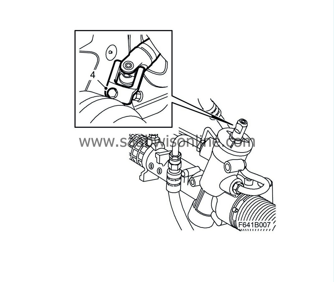
| 4. |
Remove the bolt in the lower joint. It is accessible through the wheel housing.

|
|||||||
| 5. |
Brush clean the bolt using a wire brush and blow clean with compressed air.
|
|
| 6. |
Clean out the threads in the joint with a thread tap M8 x 1.25. Blow clean with compressed air.
|
|||||||
| 7. |
Apply 74 96 268 Thread locking adhesive to the bolt.
|
|
| 8. |
Fit the bolt.
Tightening torque 30 Nm (22 lbf ft) |
|
| 9. |
Fit the wheel in accordance with WIS Group 7 Suspension, wheels - Wheels and tyres - Adjustment/Replacement - Wheels.
|
|
| 10. |
Lower the car.
|
|
| Warranty/Time Information |
In the case of customer complaint and if the car is within the warranty period , use the following information to fill out the claim:
Failed Object: 64135
Fault/Reason code: 40
Location code: 05, 06, 08 and 09 (US=9)
Warranty Type (US): 01
Repair/Action code: 05
Labour Operation (US):
6413503 Adjustment of intermediate shaft upper bolt in passenger compartment
6413504 Adjustment of intermediate shaft bolt in engine bay
6413505 Adjustment of both intermediate shaft bolts
Labour Operation (CA): E7700
Time:
Adjustment of intermediate shaft upper bolt in passenger compartment: 0.2 hr
Adjustment of intermediate shaft bolt in engine bay: 0.3 hr
Adjustment of both intermediate shaft bolts: 0.5 hr
Add $1.00 as compensation for locking fluid


