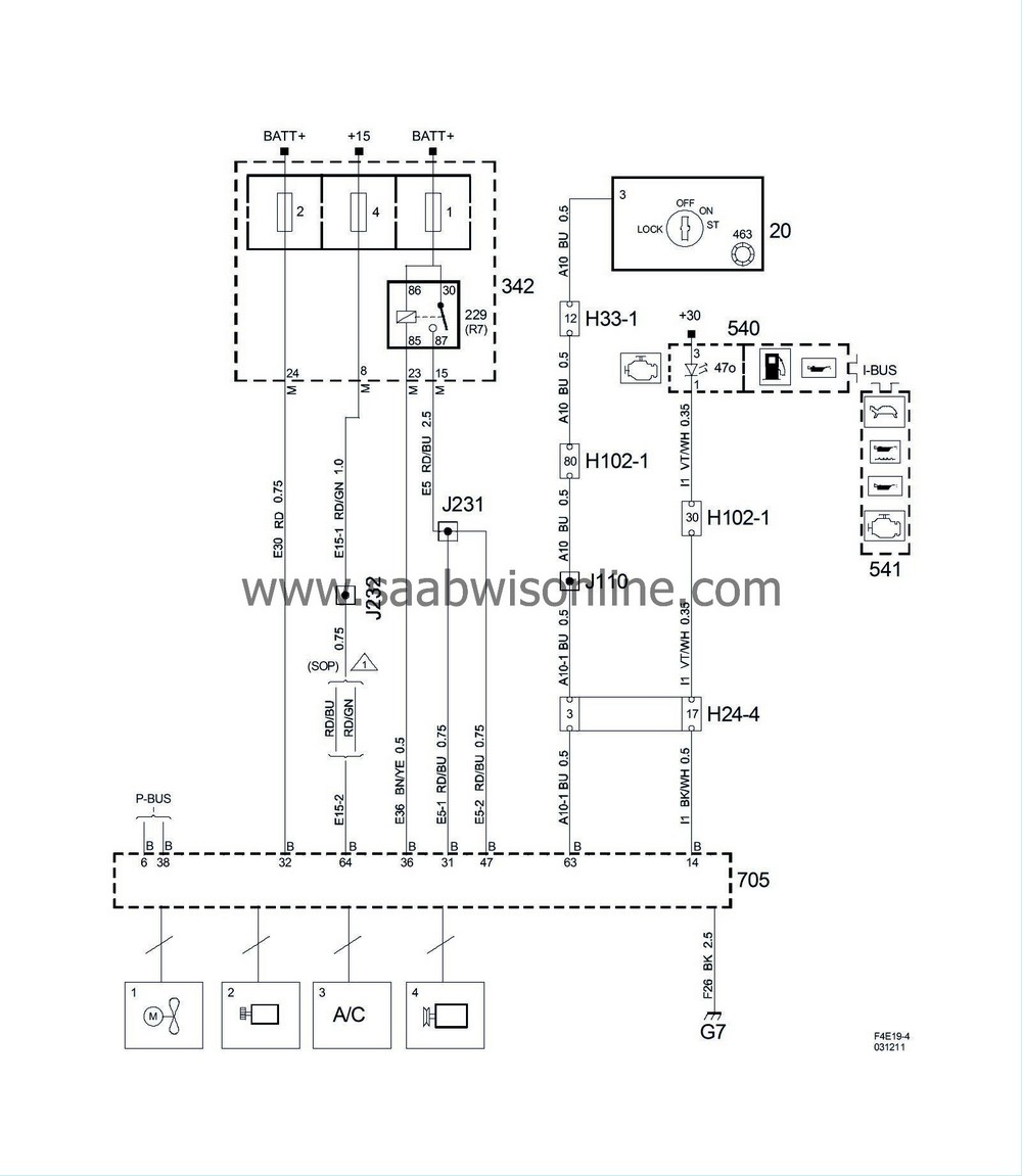
Simtec engine management system (Part 4/4)
|
|
Simtec engine management system (Part 4/4)
|
Simtec also controls the following systems:
|
No.
|
Name
location
|
Illus.
|
|
|
Components
|
|
|
20
|
Ignition switch module.
in the floor console between the front seats
|

|
|
229
|
Main relay, engine control system
in underhood electrical centre 342
|

|
|
342
|
Underhood Electrical Centre (UEC)
next to the battery
|
1
2
4
|
|
463
|
Antenna unit, immobilizer,
in the ignition switch module
|
|
|
540
|
Main instrument unit,
in front of driver in instrument panel
|

|
|
541
|
SID,
on top of instrument panel
|

|
|
705
|
Control module, Simtec
at the top of the left end of the engine
|
A
B
|
|
|
24-pin connector
|
|
|
H24-4
|
Grey connector in front of battery on side of left structural member
|

|
|
|
33-pin connector
|
|
|
H33-1
|
Black connector on the console to the left of the ignition switch
|

|
|
|
102-pin connector
|
|
|
H102-1
|
Under left A-pillar
|

|
|
|
Crimp connections
|
|
|
J110
|
In branching point to the 24 pin connectors
|

|
|
J231
|
Approx. 80 mm from branching of connector H10-15 towards the battery
|

|
|
J232
|
Approx. 40 mm from branching of reversing light switch towards the battery
|

|
|
|
Grounding points
|
|
|
G7
|
On the support bracket under the intake manifold
|

|


