Control module, PSG 16, 4-cyl. diesel (595)
| Control module, PSG 16, 4-cyl. diesel (595) |
| Location |
Control module, PSG 16, 4-cyl diesel, switch K (595K)
Control module, PSG 16, 4-cyl diesel, switch M (595M)
| Main use |
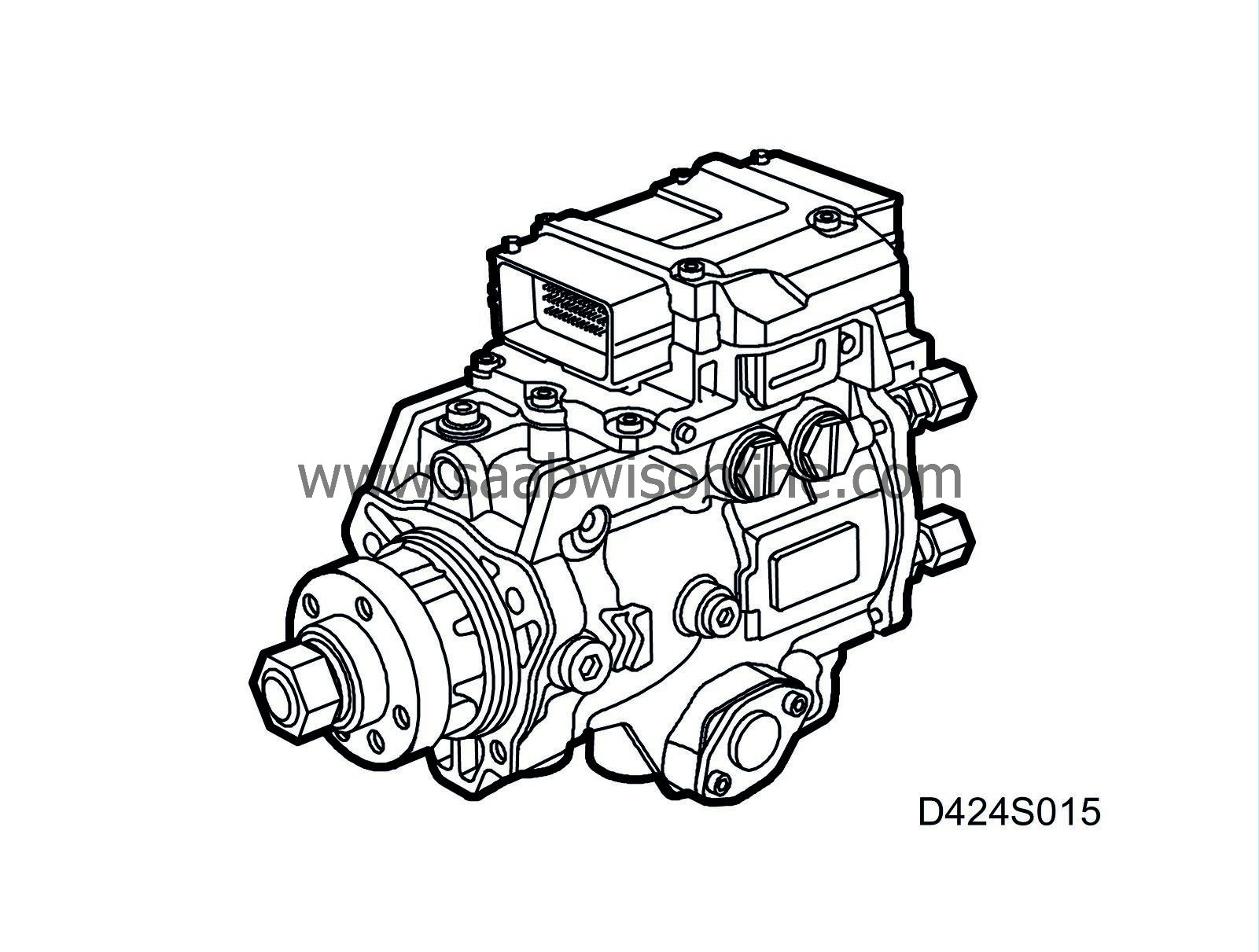
The injection pump and engine control module are now integrated into one and the same unit. Accordingly it is not possible to replace just the control module for example, but the complete unit is changed. The new engine control module can store information in flash memory, which can be reprogrammed with SPS via Tech 2.
The advantage of having the engine control module mounted on the pump is that there is less cabling and communication between pump and control module works more quickly. This results in the engine control module reacting very quickly when it has received information from the different sensors. The control module is manufactured to withstand vibrations, temperature and other outer influences better than the previous control module. The control module determines the maximum permitted fuel quantity per combustion, guided by pre-programmed limiting values and values from the different sensors. At the same time as this is taking place, a suitable time point is determined for starting the pressure build-up in the diesel pump. The control module, which is mounted on the diesel pump, has two 56-pin connections. One connection on each side of the control module.
| Type |
For more information on the control module, see, Control module, general description .

| Power supply, ground and bus communication |
|
Pin no.
|
Type of signal
|
Description
|
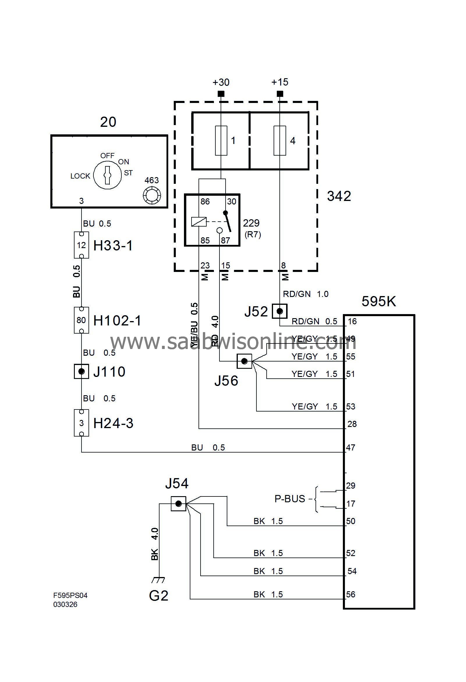
| 16 (K) | Power supply (+15 circuit) | From fuse 4 in the front electrical centre |
| 49 (K), 51 (K), 53 (K), 55 (K) | Power supply, (+30 circuit) | From main relay |
| 50 (K), 52 (K), 54 (K), 56 (K) | Ground | Grounding point G2 |
| 29 (K) | P-bus + | Signal to/from other control modules |
| 17 (K) | P-bus - | Signal to/from other control modules |


The control module is supplied with +15 and as there is no adaptation which must be stored in the memory, +30 supply is not required. In addition is an afterrunning function, which must run out before the control module releases the main relay grounding.
The afterrunning function is controlled by DICE via I- and P-bus and starts when the ignition key is turned to the OFF position, i.e. the +15 supply disappears on pin 16(K). Storage of any diagnostic trouble codes and diagnosis of the main relay take place when the afterrunning function is active. DICE holds the control module, ECM, open (approx. 60 seconds) in order to read off the engine temperature. This takes place in order to facilitate control of the radiator fan.
When erasing diagnostic trouble codes the afterrunning must have run out, i.e. the main relay has been released, before a diagnostic trouble code is finally erased.
When the ignition key is turned to the ON position, the Check Engine light comes on, which is a function check. If there is no system fault, the light is turned off after 3.5 seconds or when the engine has started, depending on which takes place first.
The fuel injection is mainly regulated according to pedal position, coolant temperature and engine speed. In the event of any fault there are replacement functions for all sensors available in the control module.


