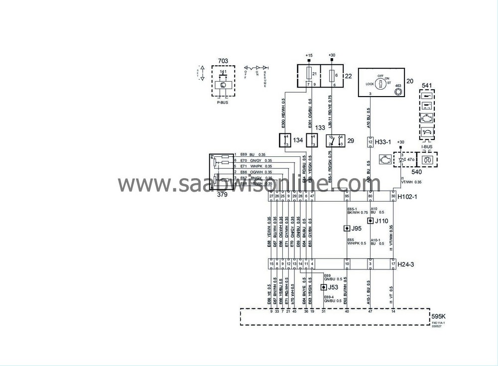
Engine management system PSG16 (Part 1/3)
|
|
Engine management system PSG16 (Part 1/3)
|

|
No.
|
Name
location
|
Illus.
|
|
|
Components
|
|
|
20
|
Ignition switch module.
in the floor console between the front seats
|

|
|
22
|
Main fuse box, dashboard,
on the short side of the dashboard by the left door
|
6
21
|
|
29
|
Brake light switch
on pedal bracket
|

|
|
133
|
Clutch switch, cruise control
on pedal bracket
|

|
|
134
|
Brake switch, cruise control
on pedal bracket
|

|
|
141
|
Cruise control switch
integrated in the switch for the direction indicators
|
|
|
379
|
Accelerator position sensor
on pedal bracket
|

|
|
463
|
Antenna unit, immobilizer,
in the ignition switch module
|
|
|
540
|
Main instrument,
in front of driver in the instrument panel
|

|
|
541
|
SID,
on top of the instrument panel
|

|
|
595K
|
Pump Steuer GerSt 16 control module, 4-cyl diesel, switch K,
in front on the engine
|

|
|
703
|
Column Integration Module,
on the steering column below the steering wheel
|

|
|
|
24-pin connector
|
|
|
H24-3
|
Grey connector in front of the battery of the side of the left structure strut
|

|
|
|
33-pin connector
|
|
|
H33-1
|
Black connector on the console to the left of the ignition switch
|

|
|
|
102-pin connector
|
|
|
H102-1
|
Under the left A-pillar
|

|
|
|
Crimp connections
|
|
|
J53
|
Approx. 120 mm from branching point crankshaft sensor towards the engine control module
|

|
|
J95
|
4D:
Approx. 60 mm from branching point to the LH front door towards the engine compartment
CV:
Approx. 30 mm from branching point to LH front door towards the engine compartment
|

|
|
J110
|
In branching point to the 24 pin connectors
|

|


