|
No.
|
Name
location
|
Illus.
|
|
|
Components
|
|
|
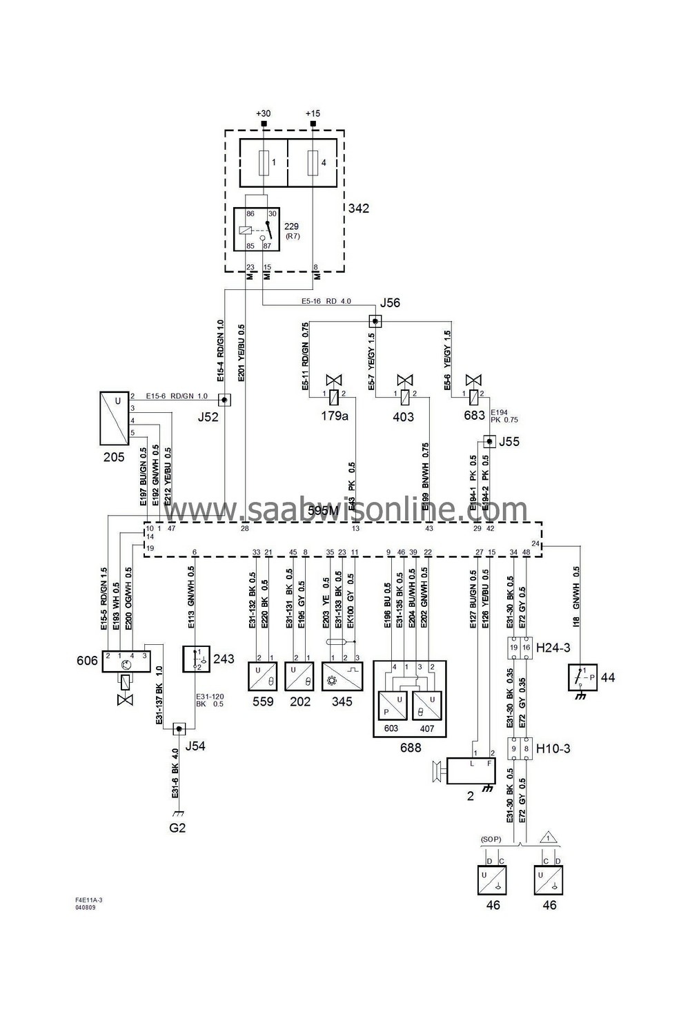
2
|
Generator,
on the front long side of the engine (right)
|

|
|
44
|
Pressure switch, engine oil,
under the generator
|

|
|
46
|
Level sensor, fuel,
in the fuel tank
|

|
|
179a
|
Solenoid valve, charge air,
in front of the glow plug control module on the battery's radiation shield
|

|
|
202
|
Coolant temperature sensor,
on the thermostat housing
|

|
|
205
|
Mass air flow sensor,
at right-hand MacPherson strut tower
|

|
|
229
|
Main relay, engine control system
in main fuse box in engine bay 342
|

|
|
243
|
Engine oil level switch
centre of the front edge of the oil pan above the oil temperature sensor
|

|
|
342
|
Main fuse box, engine bay
next to the battery
|
1
4
|
|
345
|
Crankshaft position sensor,
under the oil filter
|

|
|
403
|
Combustion circulation solenoid valve,
upper boost pressure control valve behind the glow plug control module on the battery's radiation shield
|

|
|
407
|
Intake air temperature sensor,
integrated in the intake air sensor 688 on the throttle body
|

|
|
559
|
Engine oil temperature sensor,
centre of the front edge of the oil pan
|

|
|
595M
|
Pump Steuer GerSt 16 control module, 4-cyl diesel, switch M
in front on the engine
|

|
|
603
|
Pressure sensor, charge air,
integrated in the intake air sensor 688 on the throttle body
|

|
|
606
|
EGR solenoid unit,
on front of the throttle body
|

|
|
683
|
Shut-off motor solenoid valve,
lower solenoid valve behind the glow plug control module on the battery's radiation shield
|

|
|
688
|
Intake air sensor,
on throttle body
|

|
|
|
10 pin connector
|
|
|
H10-3
|
On a bracket by the tank strap on the front edge of the fuel tank
|

|
|
|
24-pin connector
|
|
|
H24-3
|
Grey connector in front of the battery of the side of the left structure strut
|

|
|
|
Crimp connections
|
|
|
J52
|
Approx. 90 mm from the exhaust exhaust recirculation valve unit
|

|
|
J54
|
Approx. 170 mm from branching point crankshaft sensor towards the engine control module
|

|
|
J55
|
Approx. 230 mm from branching point crankshaft sensor towards the engine control module
|

|
|
J56
|
Approx. 280 mm from branching of connector H24-3 towards the engine control module
|

|
|
|
Grounding points
|
|
|
G2
|
On the side of the left structure strut by the connector bracket
|

|


