Main instrument unit, detailed description
|
|
Main instrument unit, detailed description
|
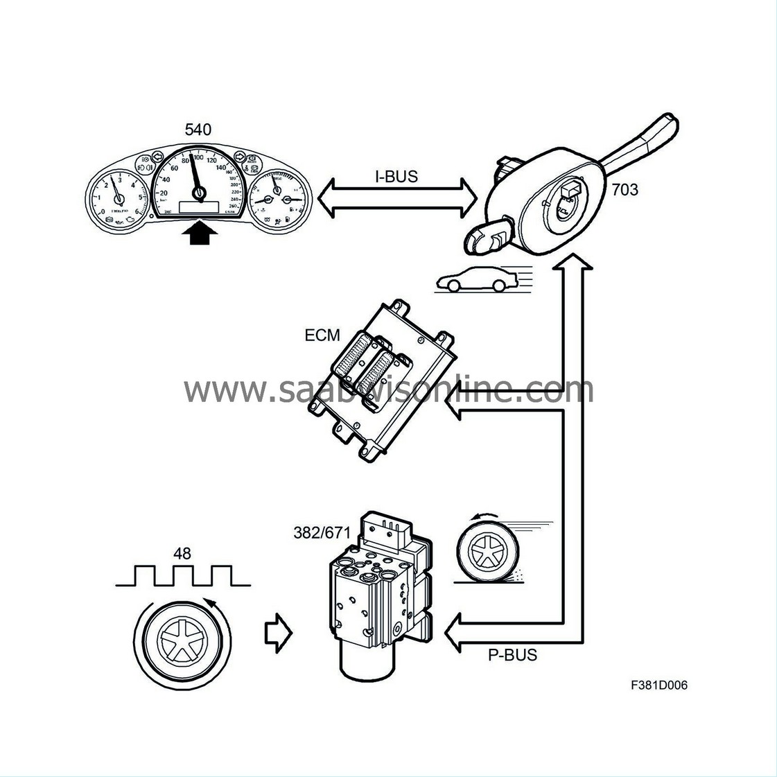
Information on speed is generated in TCS or ESP active wheel speed sensor (rear left on petrol cars and front left on diesel). The TCS/ESP control module converts the speed signal (48 pulses/rev) to wheel speed.
The speed signal is transmitted as rpm on the P-bus and is converted by the engine control module to vehicle speed after allowing for the programmed tyre dimension.
The engine control module (ECM) transmits the vehicle speed on the P-bus. CIM forwards the vehicle speed to the I-bus. The main instrument unit shows the vehicle speed on the speedometer. The control module transmits the vehicle speed on the I-bus, where information is made available to all the control modules.
Programming the speedometer
The TCS or ESP control module reads 48 pulses per wheel revolution. Depending on the tyre and wheel dimension (physical circumference), one kilometre will correspond to a different number of pulses when the engine control module receives the value from the TCS or ESP control module. It is possible to change how the engine control module interprets the total number of pulses per kilometre so that it corresponds to the current tyre dimension on the car. Programming is required so that the speedometer and odometer will provide the driver with the correct information. On many markets, it is a legal requirement that the value shown by the speedometer is between 0 and 10 km/h too high.

|
Important
|
|
If the speedometer is not programmed correctly, the displayed speed can be lower than the actual speed and SID will provide incorrect information on fuel quantity and time of arrival, etc.
|
|
|
If the speedometer is programmed for a certain type of tyre and new wheels with larger circumference are fitted, the speedometer will show a speed that is too low in comparison with the one that should be displayed.
The current tyre dimension is programmed with Tech 2.

The main instrument unit stores the driven distance and shows it on the odometer display. The odometer display incorporates a six-digit register that is continuously updated from 000000 to 999999 km (or miles) by the control module. The trip meter incorporates a five-digit register that starts at 0.0 and runs to 9999.9 km (or miles).
This information is generated in the active wheel sensors of the TCS or ESP system (rear left and right for petrol-engined vehicles, front left and rear right for diesels). The TCS/ESP control module converts the speed signal (48 pulses per revolution) into wheel speed. This speed signal is transmitted on the P-bus as the number of revolutions per minute and used by the engine control module, which converts the signal into distance and takes the programmed wheel dimensions into account. The engine control module (ECM) transmits the distance for the respective wheels on the P-bus. The CIM forwards the information on distance to the I-bus. The main instrument unit uses the distance and calculates an average between the distances of two wheels, subsequently providing road and trip information in the display.
The mileage is transmitted as bus information and is thus accessible to other control modules.

The electronic tachometer shows the current engine speed. Information on the current engine speed is generated by the crankshaft position sensor, which measures the current engine speed. The sensor is wired to the engine control module, which converts the frequency to an engine speed bus message and transmits it on the P-bus. CIM forwards the message to the I-bus. The main instrument unit displays the bus message as current engine speed, rpm, on the tachometer.
There are two different types of graduation:
|
Coolant temperature gauge
|

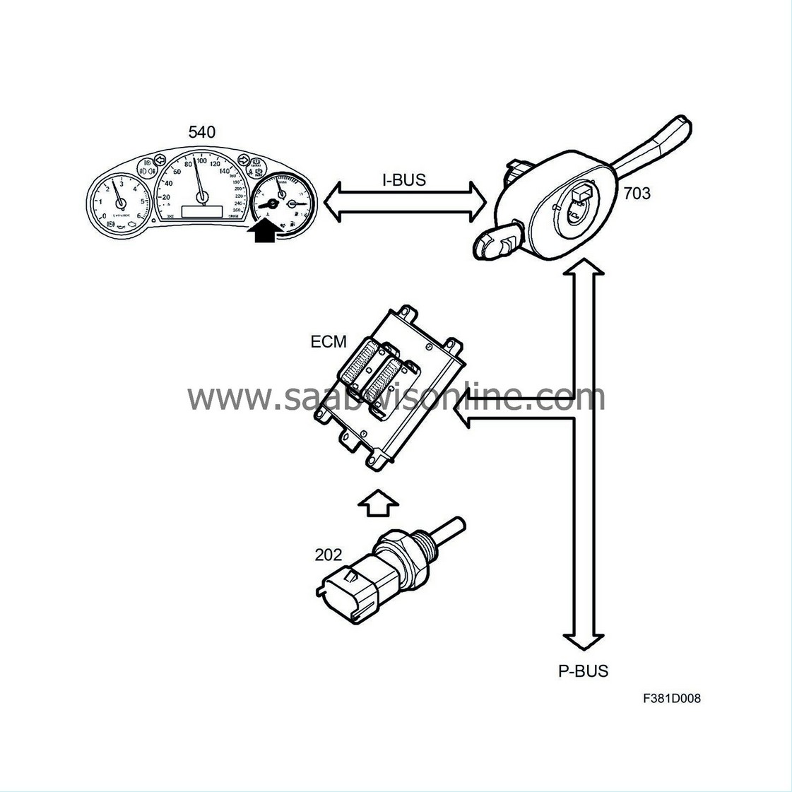
The coolant temperature gauge provides the driver with information on the engine coolant temperature. Information on coolant temperature comes from the coolant temperature sensor, which is connected to the engine control module. The engine control module converts the signal to a coolant temperature bus message and transmits it on the P-bus. CIM forwards this message to the I-bus. The main instrument unit shows the bus message on the coolant temperature gauge.

The fuel gauge gives the driver information on how much fuel is in the tank. A level sensor with variable resistance displays a value equivalent to the level of the sensor's float in the fuel tank. In petrol-engined cars, the higher the fuel level, the higher the resistance of the sensor. In diesel-engined cars, the higher the fuel level, the lower the resistance of the sensor. The sensor is connected to the engine control module, which converts the resistance value into a bus message on the fuel level which is transmitted on the P-bus. The CIM forwards the message to the I-bus. The main instrument unit uses the message and converts the value into a filtered, more stable value which is displayed by the fuel level gauge. The main instrument unit transmits the current fuel level on the I-bus. The ICM uses this value for the driving computer function.
The fuel reserve lamp comes on when the fuel quantity is below 10 litres.

The car is equipped with an electronic turbo boost gauge that provides information on the engine load. The engine control module (ECM) receives information on the current air mass/combustion from the mass air flow sensor, located between the air filter and the intake side of the turbocharger. The engine control module calculates a value corresponding to the engine load and transmits a bus message for indicating the current turbo boost on the P-bus. CIM forwards the message to the I-bus. The main instrument unit displays this value on the turbo boost gauge.
|
Warning and indicator lights
|

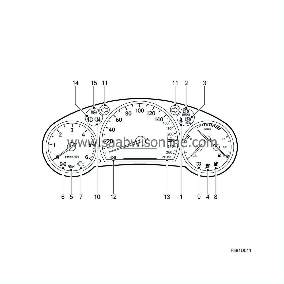
Warning and indicator lights in the main instrument unit.
Messages shown at the same time on SID.
|
Pos. no.
|
Message
|
Type
|
Colour
|
Shown on SID
|
Description
|
|
1
|
Seat belt
|
Warning
|
Red
|
|
Symbol lights up if driver not wearing seat belt.
|
|
2
|
Foot brake
|
Warning
|
Red
|
X
|
Symbol warns driver that brake fluid level is too low or of a fault in ABS system.
|
|
3
|
Handbrake
|
Warning
|
Red
|
|
Symbol lights up when handbrake is applied.
|
|
4
|
Airbag
|
Warning
|
Red
|
X
|
Symbol lights up or flashes when a fault occurs in airbag system.
|
|
5
|
Oil pressure
|
Warning
|
Red
|
X
|
Symbol lights up if engine oil pressure too low.
|
|
6
|
ABS, anti-lock brakes
|
Warning
|
Orange
|
X
|
Symbol lights up if a fault occurs in the ABS system.
|
|
7
|
Check engine
|
Warning
|
Orange
|
X
|
Check engine symbol lights up if an engine-related problem occurs. The engine control module turns on the lamp.
|
|
8
|
Quantity of fuel
|
Indicator
|
Orange
|
|
Symbol lights up when fuel quantity drops below 10 litres.
|
|
9
|
Glow plug
|
Indicator
|
Orange
|
|
Symbol lights up when ignition key turned to ON if engine coolant temperature below +5° C. Engine can be started when lamp extinguished. Applies only to cars with diesel engines.
|
|
10
|
Rear fog lights
|
Indicator
|
Orange
|
|
Symbol lights up when rear fog light is on.
|
|
11
|
Direction indicators
|
Indicator
|
Green
|
|
Symbol for right or left-hand direction indicator flashes when direction indicator stalk moved for right or left-hand turn respectively.
|
|
12
|
Driving lights, parking lights
|
Indicator
|
Green
|
|
Symbol lights up when headlamps or parking lights are on.
|
|
13
|
Cruise control
|
Indicator
|
Green
|
|
Symbol lights up when cruise control is active.
|
|
14
|
Front fog lights
|
Indicator
|
Green
|
|
Symbol lights up when front fog lights are on.
|
|
15
|
Main beam
|
Indicator
|
Blue
|
|
Symbol lights up when main beam is on.
|
|
Main instrument unit display
|
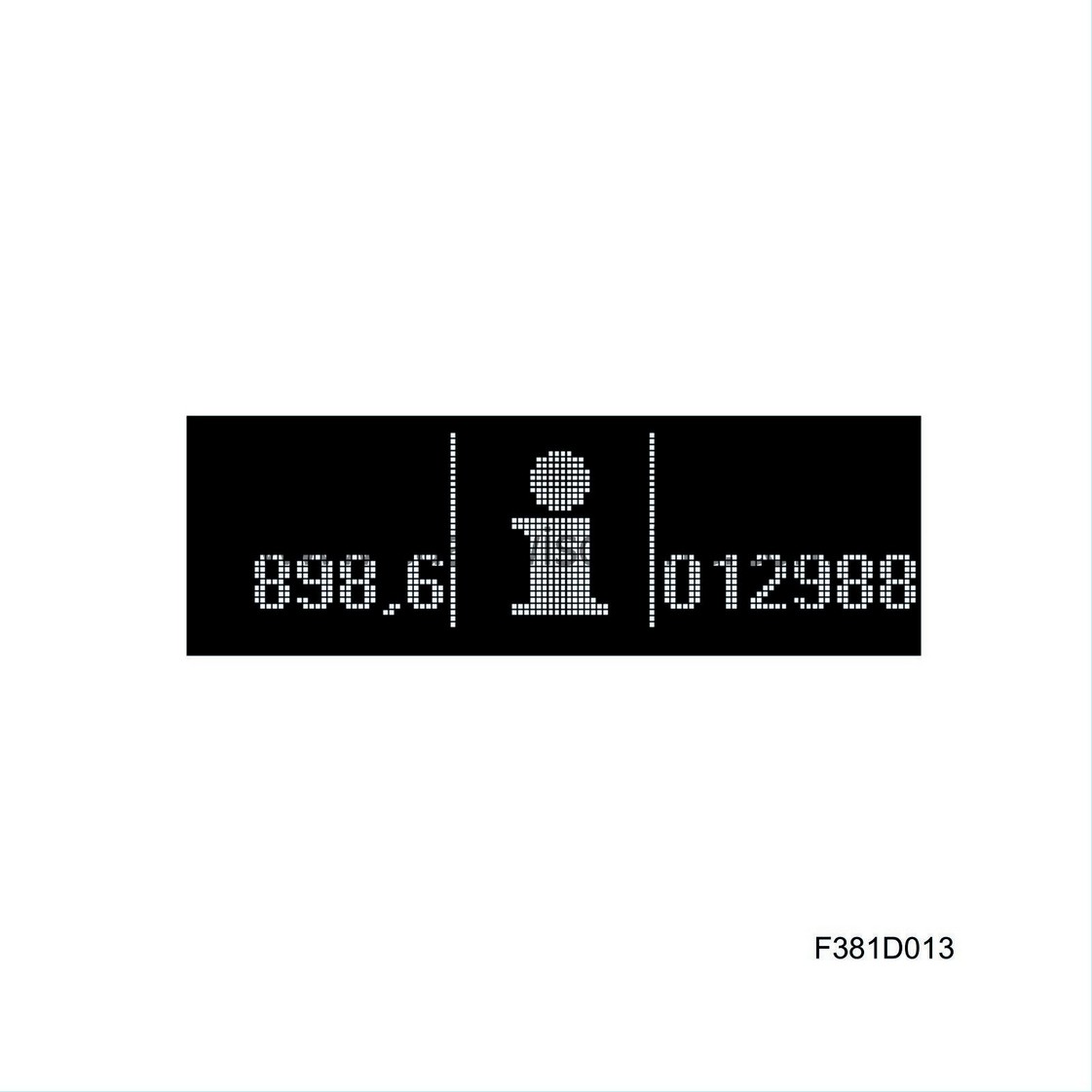
The lower part of the speedometer displays the following:
|
1.
|
Odometer and tripmeter (green)

|
|
2.
|
Indication on TCS or ESP (orange)
|
|
3.
|
Gear indication for automatic transmission (green)
|
|
4.
|
"I" for information shown on SID (orange)

|
|
5.
|
Shift up (US/CA), manual transmissions (orange)

|
|
Instrument and display lighting
|

ICM controls the instrument and button illumination with the help of:
|
•
|
Brightness control buttons (rheostat function) on SIDC.
|
|
•
|
Light sensor on rear of SID that measures the ambient light from the front.
|


