Connector PSG16 (595), sleeve replacement
| Connector PSG16 (595), sleeve replacement |
| To remove |
| 1. |
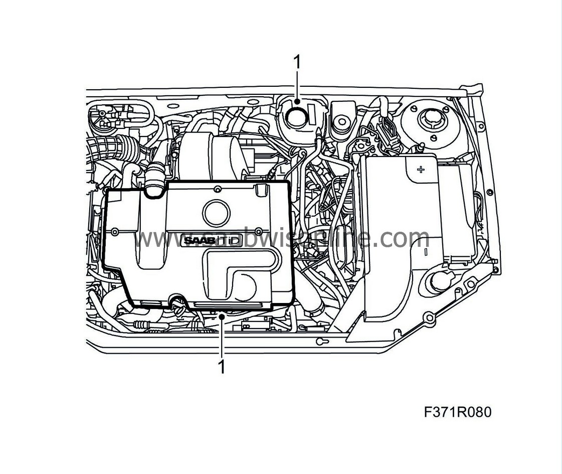
Remove the upper engine cover and undo the expansion tank cap to release any excess pressure in the cooling system.
|
|
| 2. |
Unplug the connector and detach the EGR valve from the intake manifold.

|
|
| 3. |
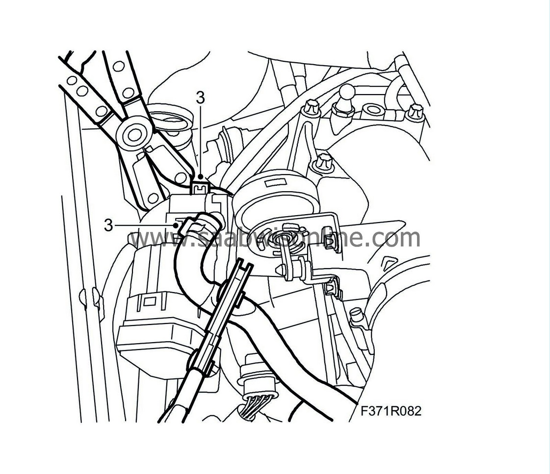
Clamp the EGR valve coolant hoses using
30 07 739 Hose pinch-off pliers
and detach the hoses from the valve.
|
|||||||||||||
| 4. |
Unplug the connector of the engine control module to which the measures apply.
|
|
| Sleeve replacement. |
| 1. |
Remove the cover.

|
|
| 2. |
Cut off the cable tie.
|
|
| 3. |
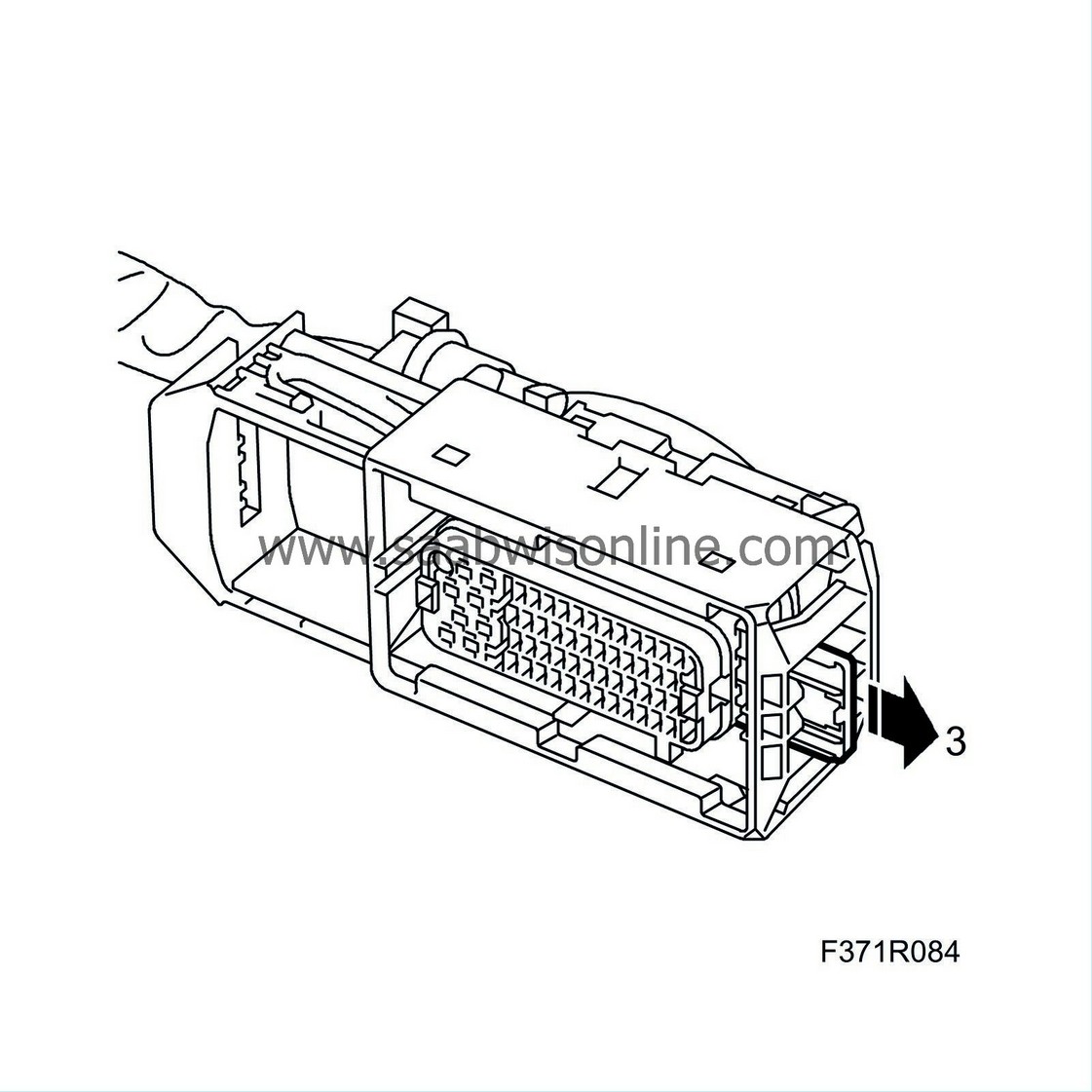
Remove the secondary catch.
|
|
| 4. |
Undo the sleeve catch by pressing in the extraction tool (part no. 85 80 151).

|
|
| 5. |
Pull out the cable with the sleeve.
|
|
| 6. |
Cut off the lead at the sleeve.

|
|||||||
| 7. |
If the lead is not long enough, splice it as follows:
|
|
| 7.1. |
Strip the insulation off of the leads.
|
| 7.2. |
Fit a shrink tube with adhesive on the line.
|
| 7.3. |
Fit sleeve (0.5-1.0 mm²), using the blue pliers from 86 12 939 Toolbox, wiring harness.
|
|||||||
| 7.4. |
Place the shrink tube over the sleeve.
|
| 7.5. |
Heat the shrink tube until it is secured.
|
| 8. |
Strip 4 mm of the lead's insulation.
|
|
| 9. |
Search for the connector in the spare parts catalogue/EPC to find the part number of the sleeve (cable terminal) to be used.
|
|
| 10. |
Fit a new sleeve on the lead using olive green pliers (0.35-0.75 mm²) from 86 12 939 Toolbox, wiring harness.
|
|
| 11. |
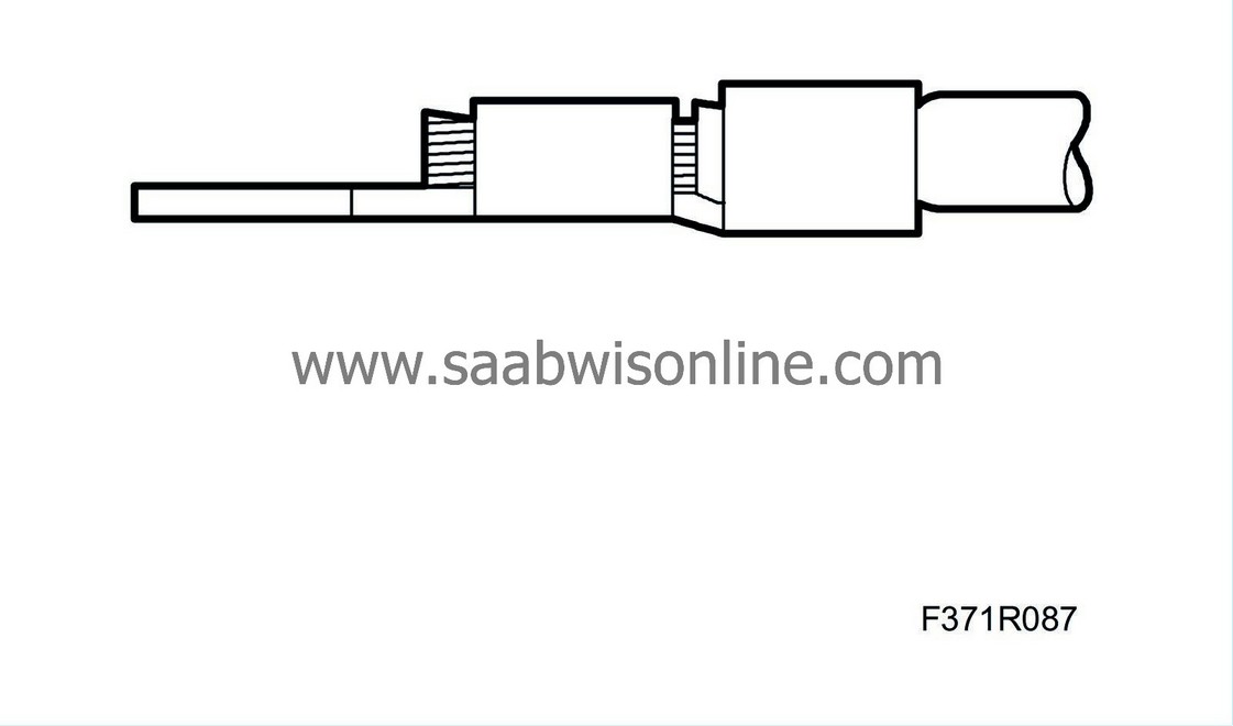
Check that the stripped lead goes through the entire clamped portion of the sleeve and that the insulation is properly clamped.
|
|
| 12. |
Press the sleeve into the connector through the seal.
|
|
| 13. |
Check that the sleeve is properly secured.
|
|
| 14. |
Check that the sleeve's depth of engagement is the same as the other sleeves in the connector.

|
|
| 15. |
Fit the secondary catch.

|
|
| 16. |
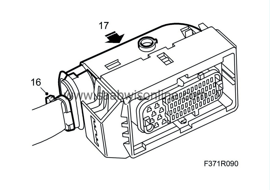
Secure the leads with a cable tie.
|
|
| 17. |
Fit the cover.
|
|
| 18. |
Use a mirror to check that the engine control module pins are straight.
|
|||||||||||||
| To fit |
| 1. |
Plug in the engine control module connector.
|
|
| 2. |
Fit the EGR valve and plug in the connector.

|
|
| 3. |
Check the function of the remedied line by using the diagnostic tool to obtain any read values. For information on the function of the pins/sleeves, see
Measurement values, control module connections PSG 16
.
|
|
| 4. |
Attach the hoses to the valve and remove the hose pinch-off pliers.
|
|
| 5. |
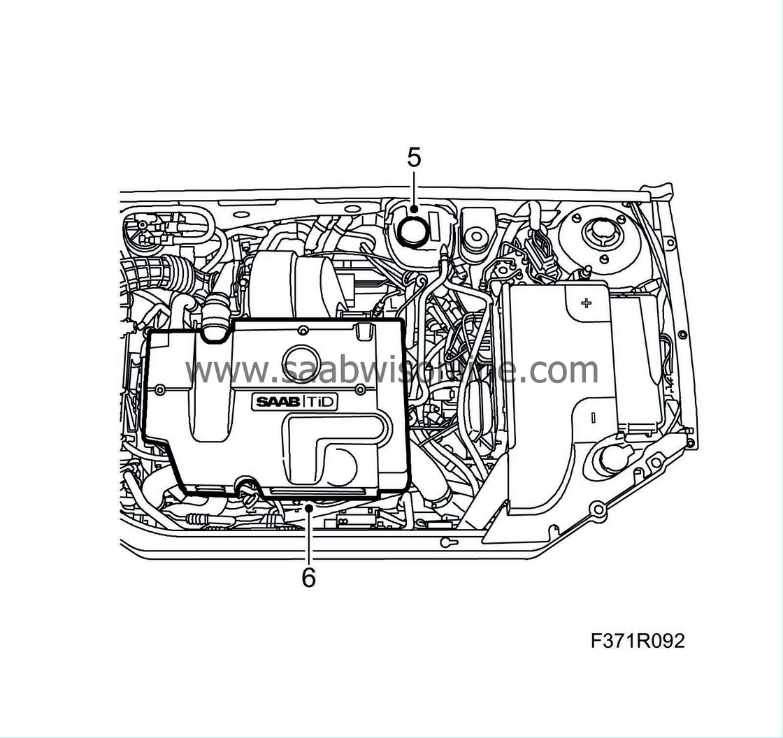
Screw on the expansion tank cap.
|
|
| 6. |
Fit the upper engine cover.
|
|
| 7. |
Clear all diagnostic trouble codes.
|
|
| 8. |
Carry out one driving cycle, i.e. run the car with varying engine load and engine speed for five minutes.
|
|
| 9. |
Read diagnostic trouble codes.
|
|


