(551-2432 utg. 2) Securing the adjusting housing, handbrake lever
Symptom: Handbrake lever jamming/cannot be lowered.
|
MODIFICATION INSTRUCTION
|
|
Bulletin Nbr:
|
551-2432 utg. 2
|
|
Date:
...........
|
Mars 2004
|
|
Market:
|
enl. lista
|
|
|
Securing the adjusting housing, handbrake lever
|
|
Customer Satisfaction Campaign 154 20
|
Cars in stock must be rectified before delivery.
A personal communication must be sent to the owners of cars already delivered requesting them to get in touch with the nearest Saab garage as soon as possible to have the fault rectified.
Saab 9-3 (9440) RHD within the following Vehicle Identification Number range:
4D:
M03-04 31000001 - 41011608
CV:
M04 46000001 - 46003610
The handbrake lever adjusting housing can twist after a while or when major force is applied to the handbrake release button. Similarly, the gear segment can twist forward. In both cases this leads to the working travel decreasing and the play increasing. At this point it becomes almost impossible to release a handbrake which has been too firmly applied, especially if it is not possible to lift the handbrake lever before pressing the button.
Symptom description
Handbrake lever jamming/cannot be lowered.
79 63 937 Screw (x1)
79 75 535 Screw (x1)
If the handbrake lever assembly must be replaced:
12 788 216 Handbrake lever assembly RHD
|
Note
|
|
Estimated defective production issue for handbrake lever assembly is 1%.
|
If the height of the handbrake lever must be adjusted when replacing the lever assembly:
12 788 227 Spacer 4 mm
12 788 228 Spacer 5 mm
12 786 769 Spacer 6 mm
12 788 229 Spacer 7 mm
When fitting the modification identity plate
12 785 148 Modification identity plate
16-30 15 815 Cleaning agent, Teroson FL T875, sufficient for 50-100 cars
Before proceeding, check box B1 of the modification identity plate. From and including M04, and for certain markets, there is the table "Table of Modifications" in the car's Warranty and Service Book. A modification identity plate must be fitted in accordance with the section "Fitting the modification identity plate" where local directives require the marking of the car. If the box is not marked, continue as follows:
|
1.
|
Remove the driver's seat in accordance with WIS "Body - Seats - Adjustment/Replacement - Front seat".
|
|
2.
|
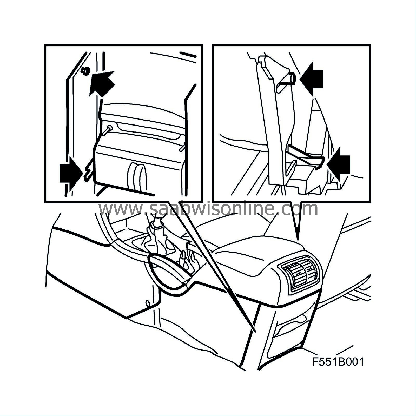
Remove the floor console rear cover and side panel.
|
|
3.
|
Slacken the handbrake adjustment enough so that the cable can be released from the centre console.

|
|
4.
|
Raise the handbrake lever until it reaches the centre console.
|
|
5.
|
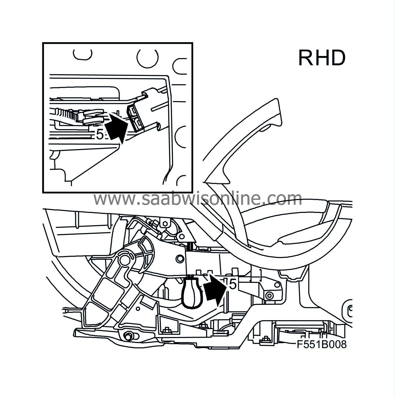
Press the white adjusting housing forwards inside the handbrake lever using a screwdriver or a drill bit, 7 mm, inserted from below.
The small illustration shows the adjusting housing seen from below (best seen with a mirror).
|
|
6.
|
Using a punch, mark the position of the hole 22 mm down on the arm in accordance with the illustration.

|
|
7.
|
Press the adjusting housing to its front position while drilling a 3 mm hole straight through the housing and fit screw 79 63 937 (long screw). Blow clean from drilling filings inside the handbrake lever.
|
Note
|
|
Fit a piece of metal plate between the handbrake lever and the compartment inside the lever so that the drill bit does not enter the compartment.
|
|
|
8.
|
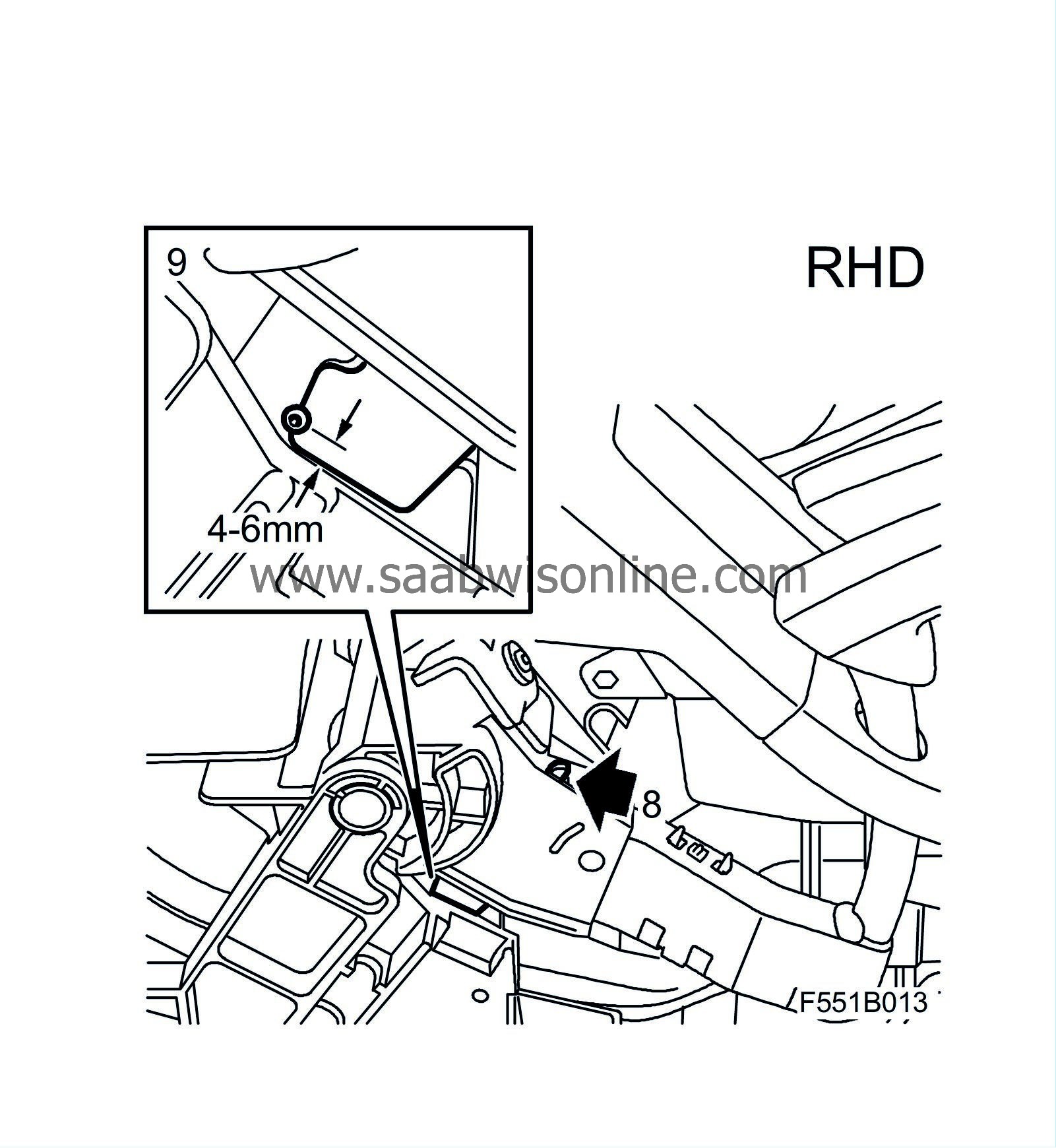
Lower the lever to its lowest position and then raise it three notches. Press the gear segment backwards as far as possible using a large screwdriver. Tap carefully with a hammer on the screwdriver to ensure that the gear segment reaches its rearmost position.
|
|
9.
|
Make a punch mark in the intermediate area, 4-6 mm from the lower edge (the screw head must run freely but must not come up too high).
|
|
10.
|
Check that the gear segment is still in its rearmost position and remains there during the drilling.
First drill a 2mm hole and then drill it up to 2.5 mm and fit screw 79 75 535 (short screw). The drill bit will automatically penetrate the softer aluminium material.
|
Note
|
|
The length of the drill bit outside of the chuck should be at least 40 mm. Take care that the chuck does not hit the housing when the drill bit penetrates the material. This can break the drill bit.
|
|
|
11.
|
Vacuum clean the metal filings.
|
|
12.
|
Fit the handbrake cable.
|
|
13.
|
Adjust the handbrake cable in accordance with WIS "Brakes - Handbrake - Adjustment/Replacement - Adjusting the handbrake cable".
|
|
14.
|
Test the release function by
|
|
|
•
|
pulling the handbrake lever to notch 4-6
|
|
|
•
|
pressing the handbrake lever downwards with a force of approximately 100 N (22.5 lbf) which equates to a weight of 10 kg (22 lb) while pressing the release button twice.
|
|
15.
|
Following which, check that it is easy to release a firmly applied handbrake lever.
|
|
16.
|
Does it operate OK?
YES:
Continue with step 17.
NO:
Replace the handbrake lever assembly in accordance with WIS "Brakes - Handbrake - Adjustment/Replacement - Handbrake lever". Continue with step 18.
|
Note
|
|
Handbrake levers are supplied in different conditions, modified with/without screws. Irrespective of its condition, the handbrake lever is correct and must not be modified in accordance with the above.
|
|
|
17.
|
Fit the floor console rear side panel and cover.
|
|
18.
|
Fit the driver's seat in accordance with WIS "Body - Seats - Adjustment/Replacement - Front seat".
|
|
Marking the modification identity plate
|
After carrying out the procedure, box B1 on the modification identity plate must be marked. From and including M04, and for certain markets, there is the table "Table of Modifications" in the car's Warranty and Service Book. Mark the box with the number "7" if the procedure was carried out by the importer or with the number "8" if carried out by the dealer.
|
Fitting the modification identity plate M04
|
|
Note
|
|
A modification identity plate must only be fitted where local directives require the marking of the car.
|
|
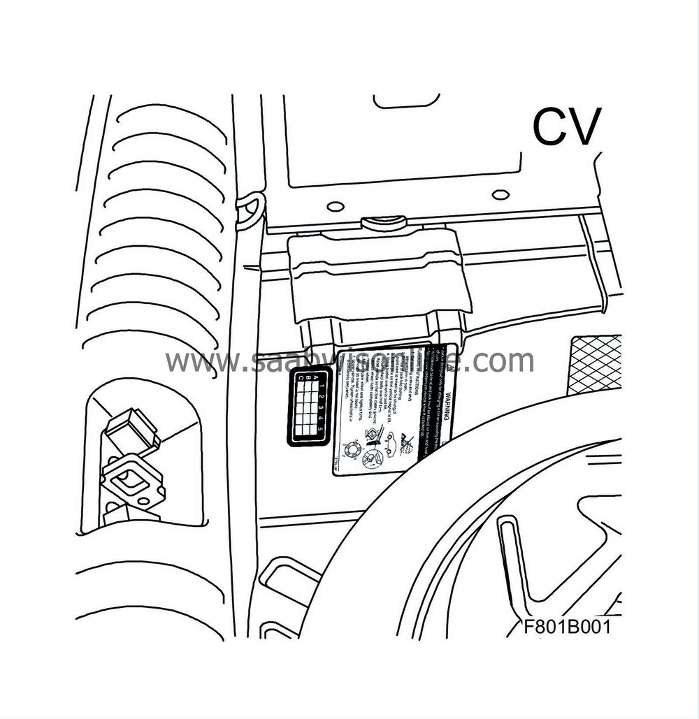
1.
|
Open the boot lid and lift up the floor panel.
|
|
2.
|
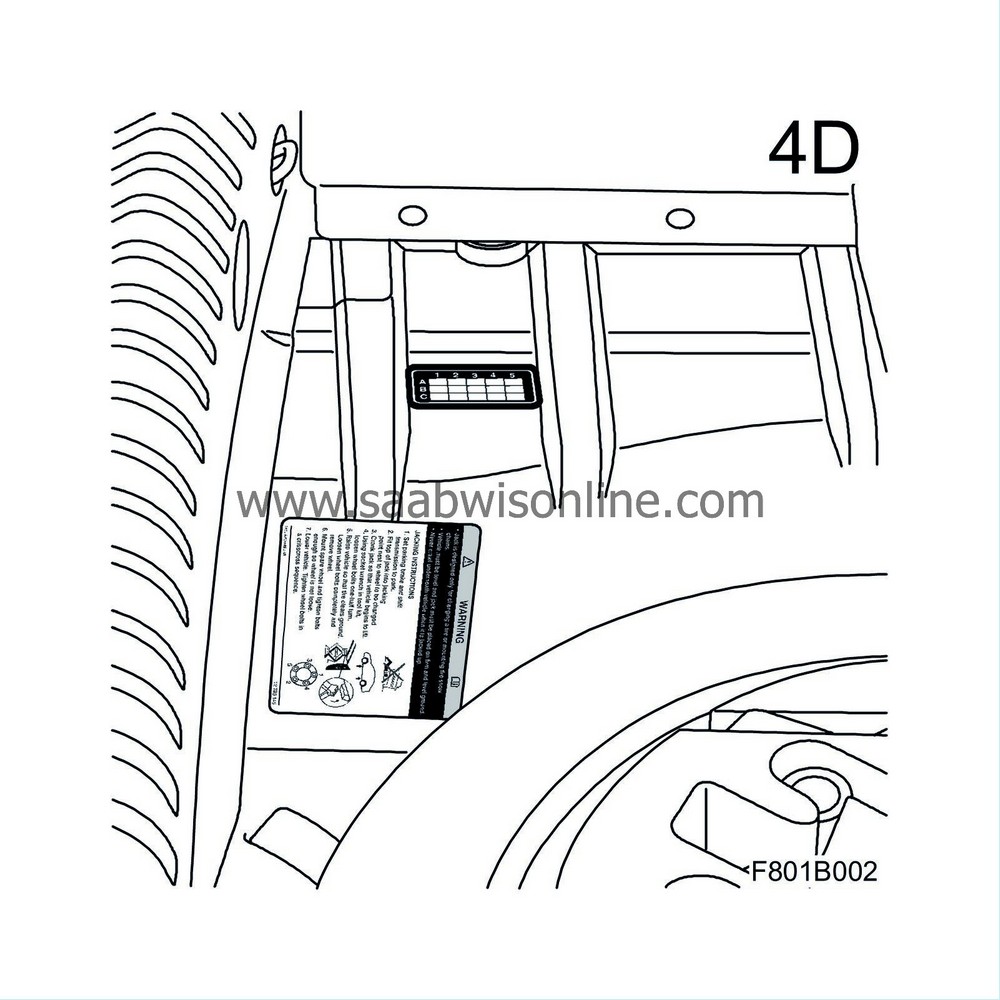
Clean the body surface location for the plate with Teroson FL T875. Remove the protective plastic backing from the plate.
|
|
3.
|
Press in the plate in accordance with the illustration.
|
|
4.
|
Mark the plate in the assigned box, lower the floor panel and close the boot lid.
|
|
Warranty/Time Information
|
See separate information.


