(881-2529 utg. 2) Updating the hood system
|
MODIFICATION INSTRUCTION
|
|
Bulletin Nbr:
|
881-2529 utg. 2
|
|
Date:
...........
|
Augusti 2005
|
|
Market:
|
Enligt sep. lista
|
|
Customer Satisfaction Program 154 40
|
Cars in stock must be rectified before delivery.
A personal communication must be sent to the owners of cars already delivered requesting them to get in touch with the nearest Saab garage as soon as possible to have the fault rectified.
A. Checking/replacement of holder for position sensor
Saab 9-3 CV M04 within Vehicle Identification Number range 46000001 - 46018565
B. Checking, securing and, if necessary, replacement of hydraulic lines
Saab 9-3 CV M04 within VIN ranges:
46000001 - 46020045 black roof / grey headlining
46000001 - 46020083 black roof / beige headlining
46000001 - 46020240 blue roof / grey headlining
46000001 - 46020243 blue roof / beige headlining
C. Updating the STC/BCM software
Saab 9-3 CV M04-M05 with remote opening of soft top within VIN range 46000001 - 56011392
A. Checking/replacement of holder for position sensor
On certain cars the position sensor for the soft top cover is in an incorrect position. This may mean that the roof cannot be operated. To rectify the problem the holder for the position sensor must be replaced with a new one.
B. Checking, securing and, if necessary, replacement of hydraulic lines
On certain cars the hydraulic lines to the lock on the first bow are twisted where the roof is folded when the soft top is lowered. In some cases this may lead to crush damage on the lines. This crush damage could lead to the hydraulic lines fracturing and starting to leak hydraulic oil.
C. Updating the STC/BCM software
When the soft top is lowered with the remote control (i.e. long press on the remote control) and the boot lid is open then the soft top cannot be operated. The problem also remains after the boot lid is closed. In order that full functionality can be reached the STC/BCM must be updated with new software.
A. Checking/replacement of plastic holder for position sensor
If the sensor holder must be replaced:
12 760 319 Holder 1-2 per car
79 71 864 Cable tie 2-4 per car
B. Checking, securing and, if necessary, replacement of hydraulic lines
12 765 357 Fastening kit
If the hydraulic lines must be replaced (1% estimated for replacement):
12 833 516 Hydraulic line
92 150 191 Cable tie 4 per car (supplied in packs of 50)
79 71 864 Cable tie 2 per car
12 765 356 Cable tie 3 per car
79 84 784 Cable tie
12 833 524 O-ring kit (not all parts in the kit shall be used)
12 833 940 Clips 2 per car, applies to cars within VIN range 46000001 - 46001629
93 160 548 Hydraulic oil (delivered in a batch of 12 bottles) (each bottle sufficient for approx. 50 cars)
96 98 846 Chafe protection tape (sufficient for 5 cars)
Electrical tape
For fitting the modification identity plate (not US/CA):
12 785 148 Modification identity plate
93 160 907 Cleaning agent Motip Dupli, aerosol 400 ml (sufficient for 50-100 cars)
Not US/CA:
Before proceeding, check box B5 of the modification identity plate. From and including M04, the table "Table of Modifications" can be found in the car's Warranty and Service Book. A modification identity plate must be fitted in accordance with the section "Fitting the modification identity plate" where local directives require the marking of the car. If the box is not marked, continue as follows.
A. Checking/replacement of holder for position sensor
|
1.
|
Remove the soft top cover. See WIS - 8. Body - Hood system - Adjustment/Replacement - Soft top cover.
|
|
2.
|
Check that the sensor is correctly fitted in the holder and that the sensor has not moved backward.
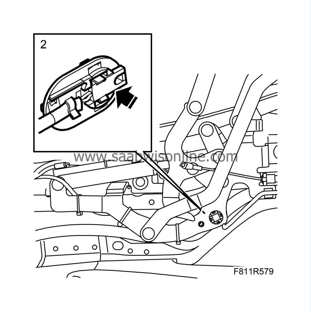
|
|
3.
|
Guide the hinges to closed and locked position, by moving them manually.
Right-hand side:
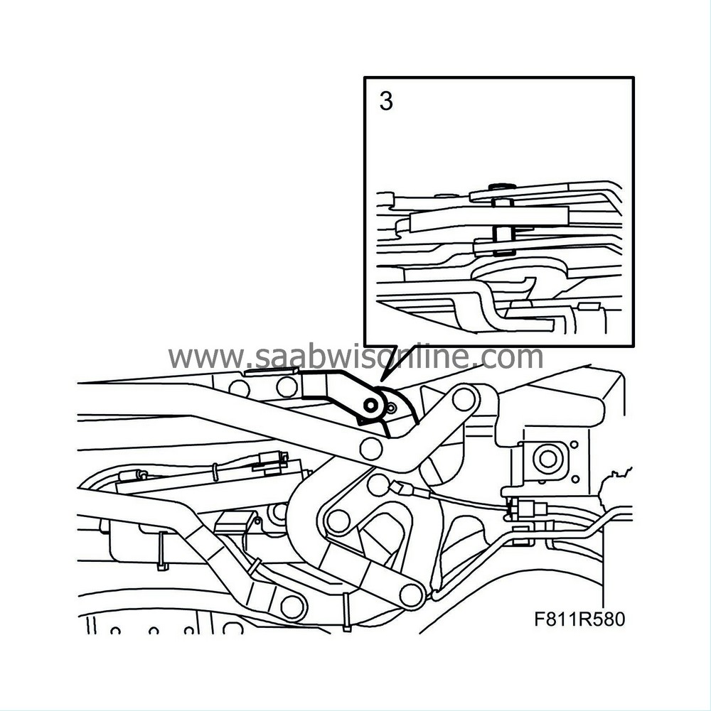
Left-hand side:
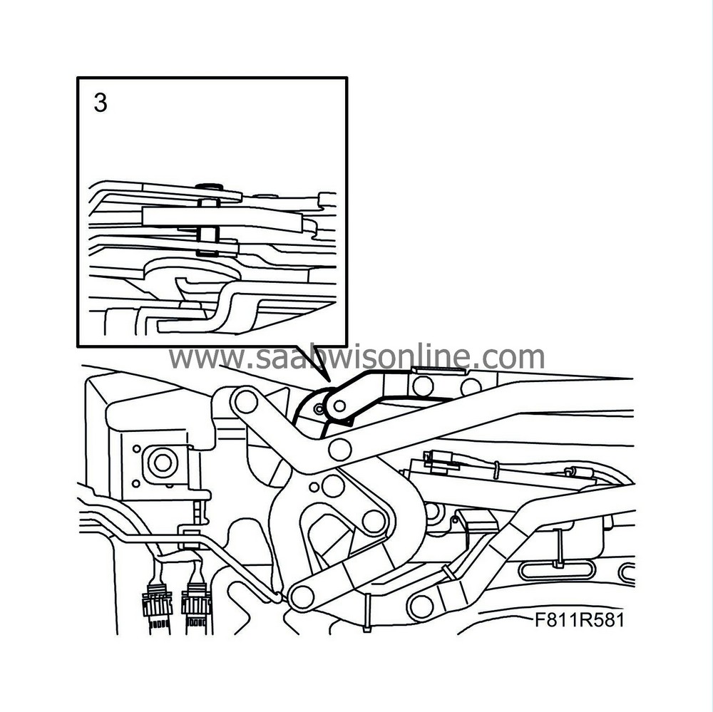
|
|
4.
|
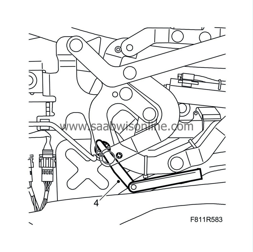
Measure the distance between the position sensor and the hinge using a feeler gauge.
Right-hand side:
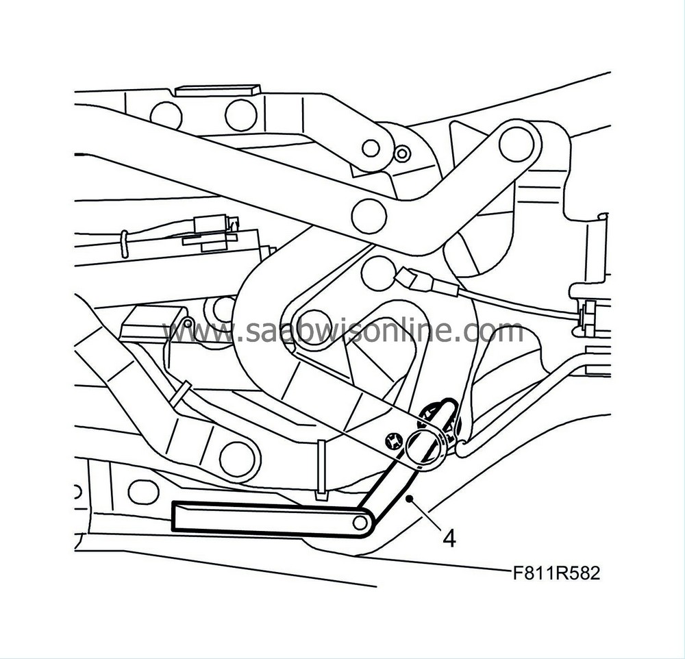
Left-hand side:
|
|
5.
|
If the distance between the position sensor and the hinge is more than 1.9 mm, replace the holder with a new one. See WIS 8. Body - Hood system - Adjustment/Replacement - Position sensor, soft top cover locked (562LH/RH).
|
|
6.
|
Fit the soft top cover. See WIS - 8. Body - Hood system - Adjustment/Replacement - Soft top cover.
|
B. Checking, securing and, if necessary, replacement of hydraulic lines
|
1.
|
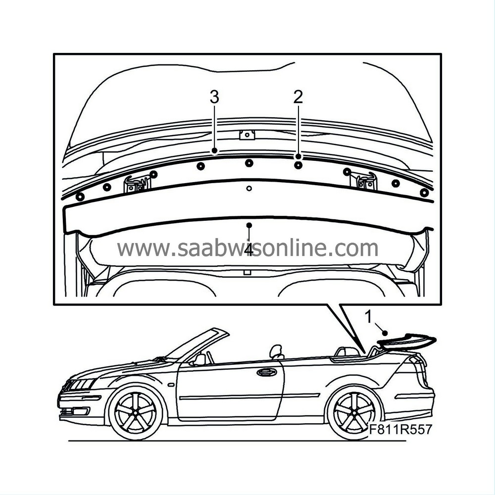
Lower the soft top and allow the soft top cover to be open.
|
|
2.
|
Remove the clips' centre pins to the mounting plate.
|
|
3.
|
Remove the mounting plate with the clips.
|
|
4.
|
Lift the trim in the front and take it out.
|
|
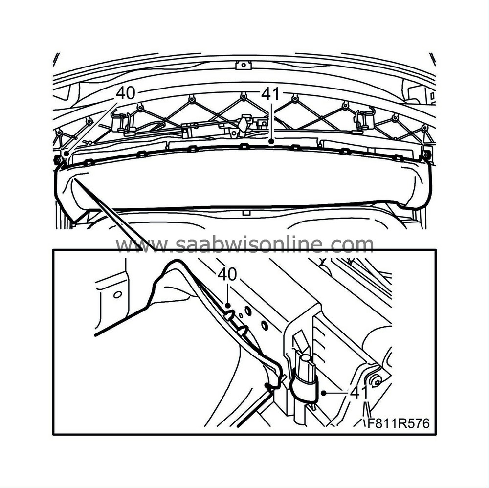
5.
|
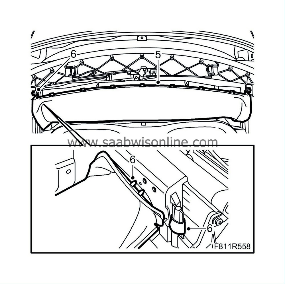
Unhook the headlining attachment eyes to the first bow on the right-hand side.
|
|
6.
|
Remove the headlining plastic plugs and the outer roof attachment eye on the right-hand side of the first bow.
|
|
7.
|
Operate the soft top to its centre position, the soft top first bow must point straight up.
|
|
8.
|
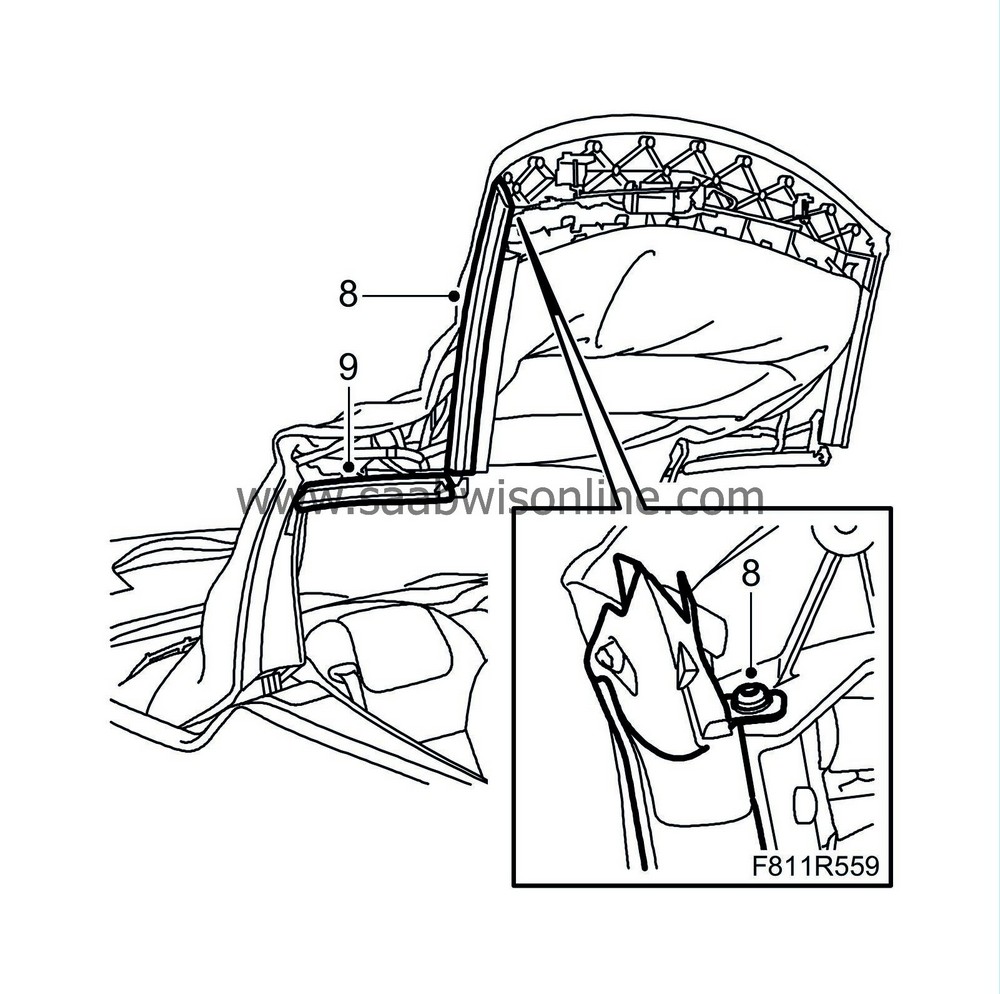
Remove the screw and the seal from the front rail.
|
|
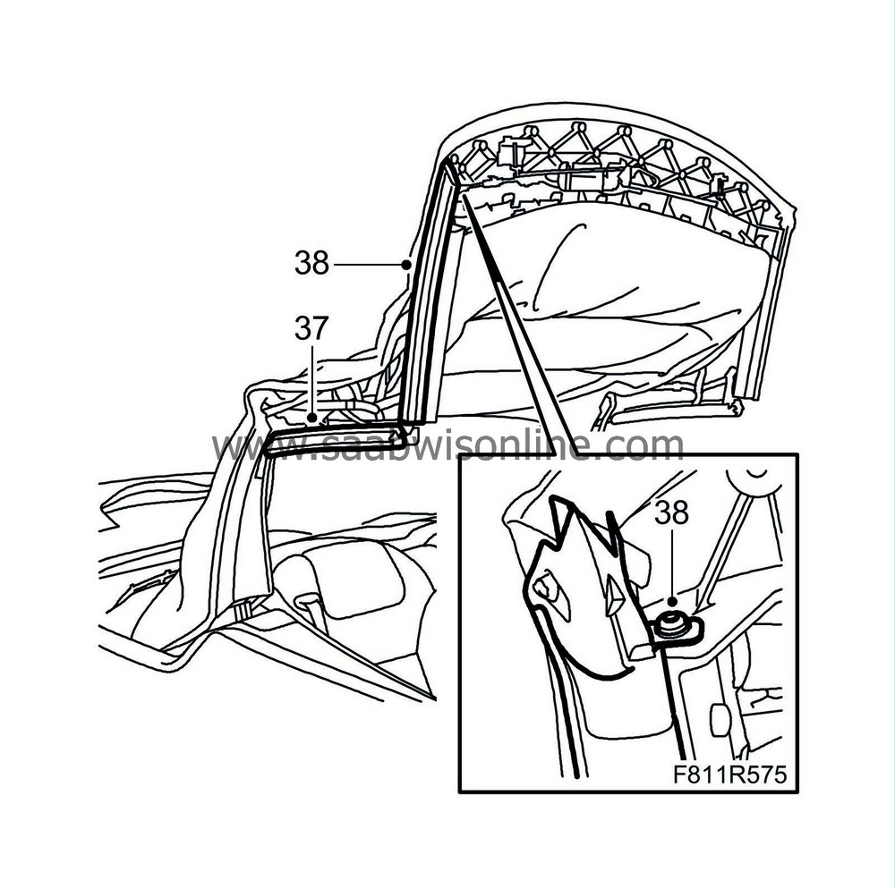
9.
|
Remove the seal from the centre rail.
|
|
10.
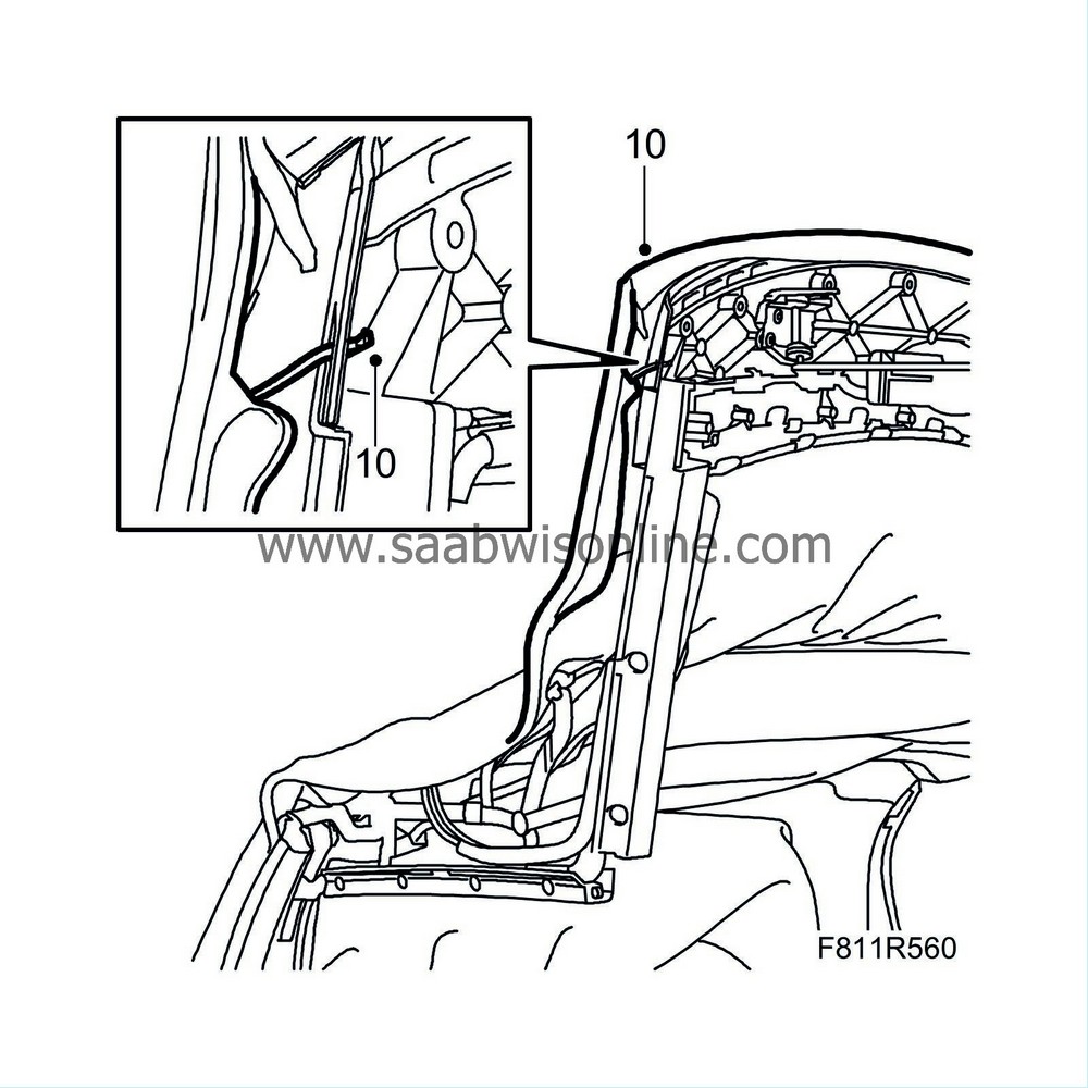
|
Detach the outer roof from the right-hand side of the first bow.
|
|
11.
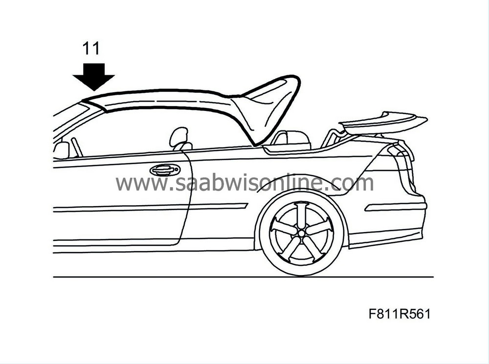
|
Raise the soft top and lock the first bow. Do not close the sixth bow.
|
|
12.
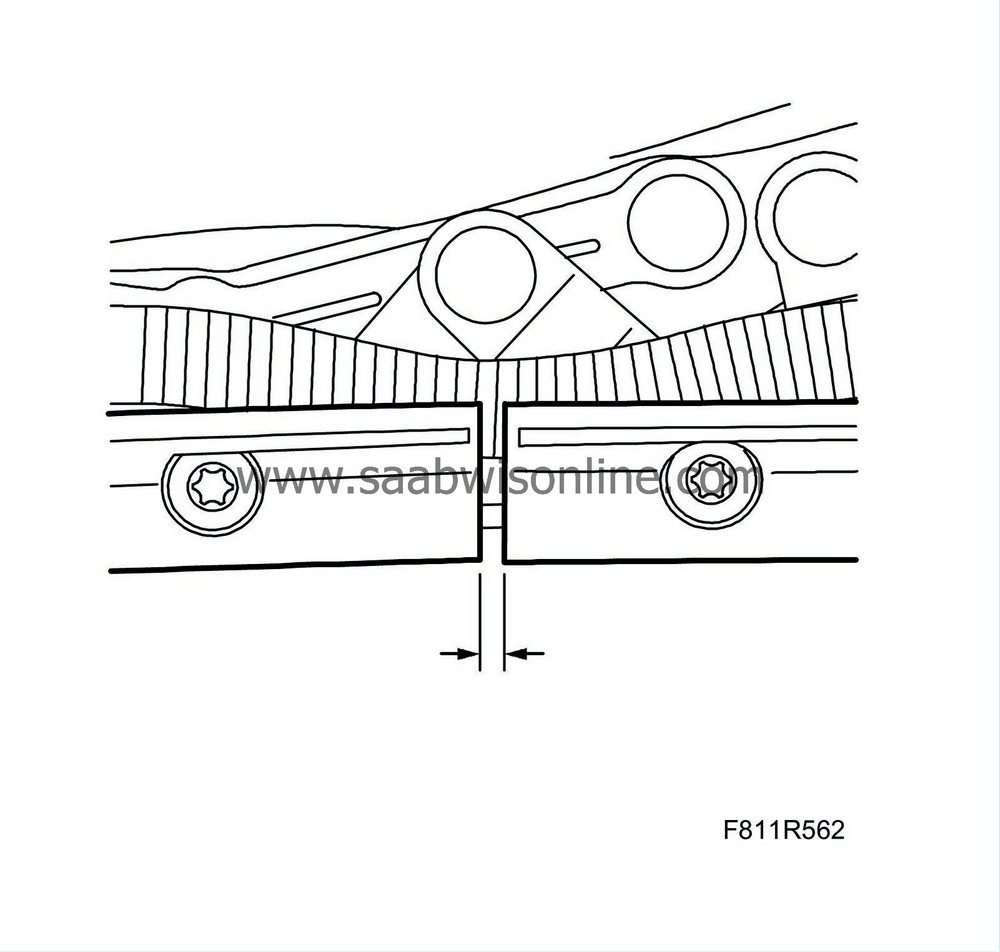
|
Measure the distance between the front and the rear rail. Note down and save the measurement for later use.
|
|
13.
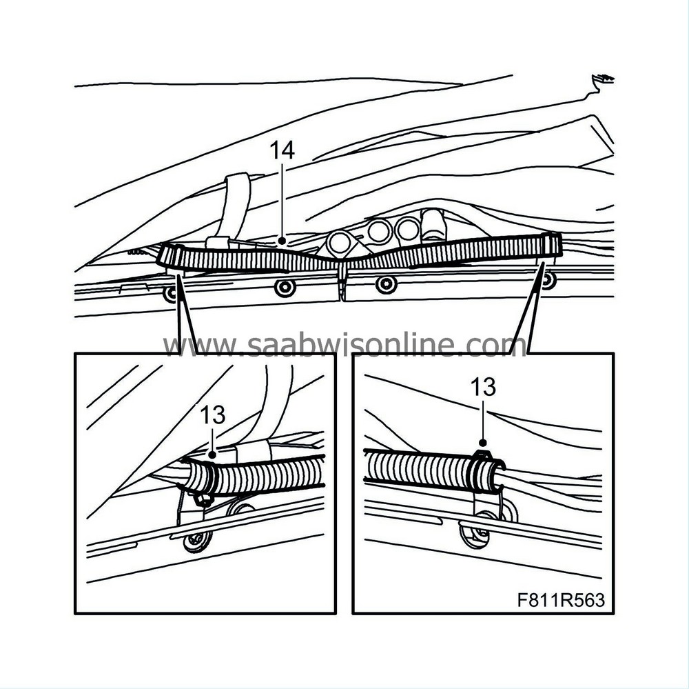
|
Remove the cable ties.
|
|
14.
|
Remove the flexible hose.
|
|
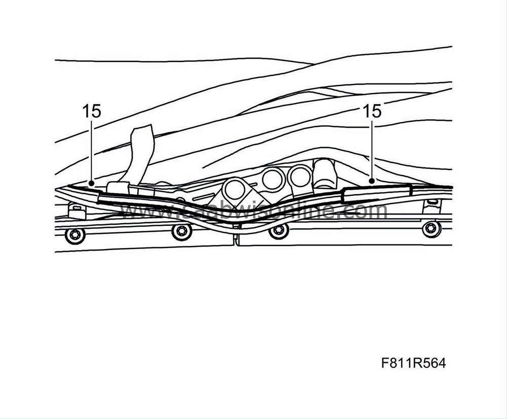
15.
|
Remove the chafe guard.
|
|
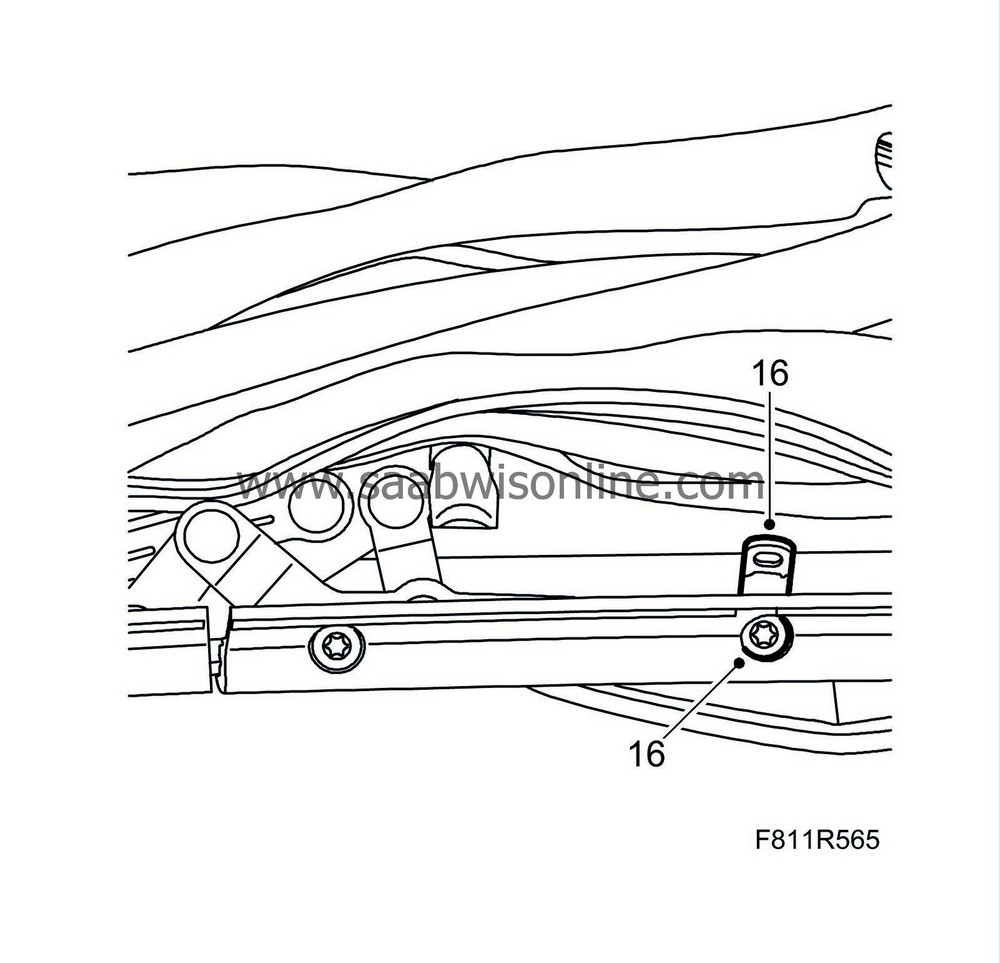
16.
|
Remove the screw and the bracket for the line assembly, from the front rail.
|
|
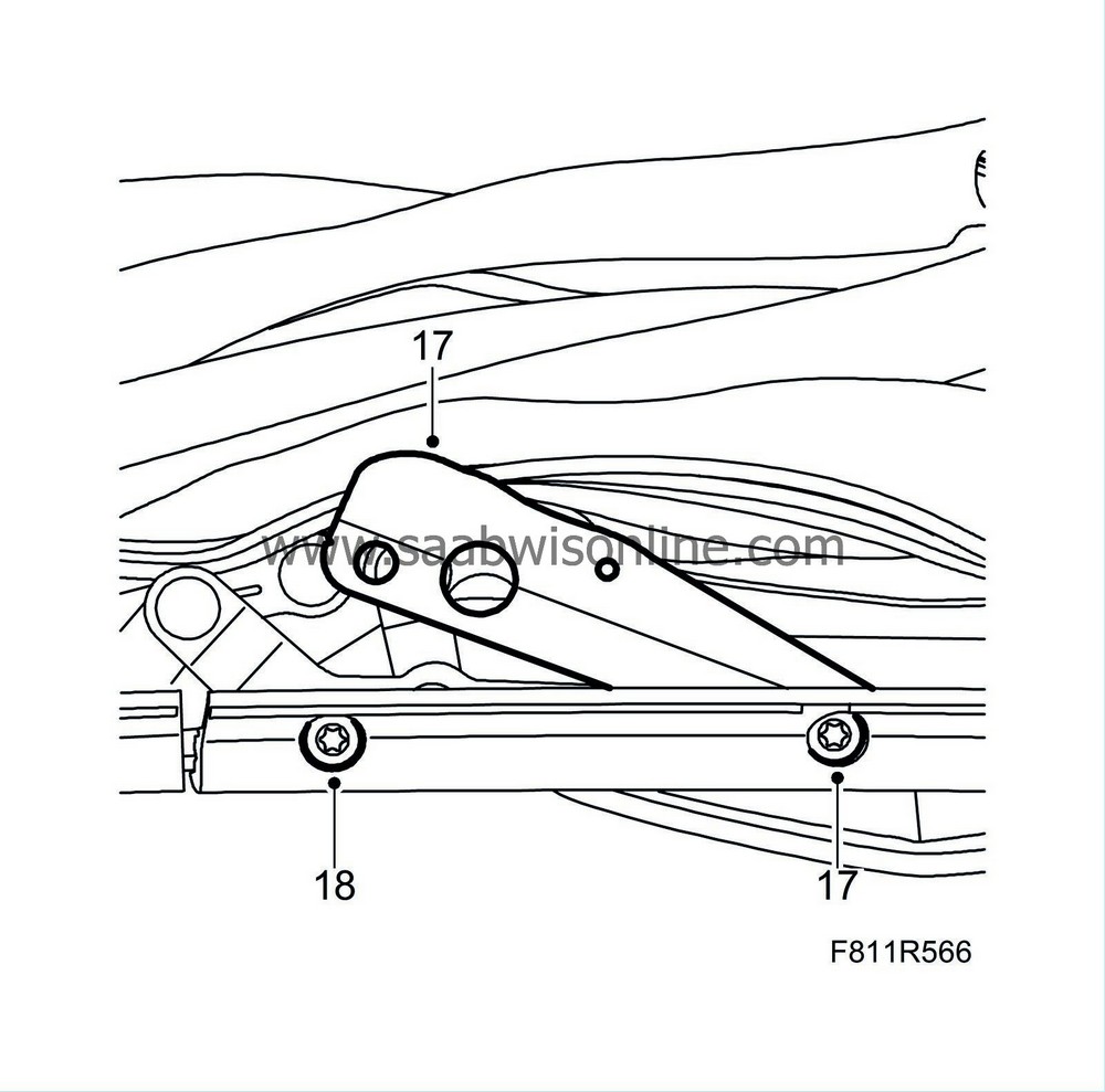
17.
|
Align the new bracket in the correct position and fit a screw. Tighten the screw loosely.
|
|
19.
|
Align the bracket in the correct position and fit a screw. Tighten the screw loosely.
|
|
20.
|
Check that the distance between the front and the centre rail is equivalent to the measurement noted down earlier in step 12. If necessary, adjust the rail so that the distance is correct.
|
|
21.
|
Tighten both of the screws for the bracket.
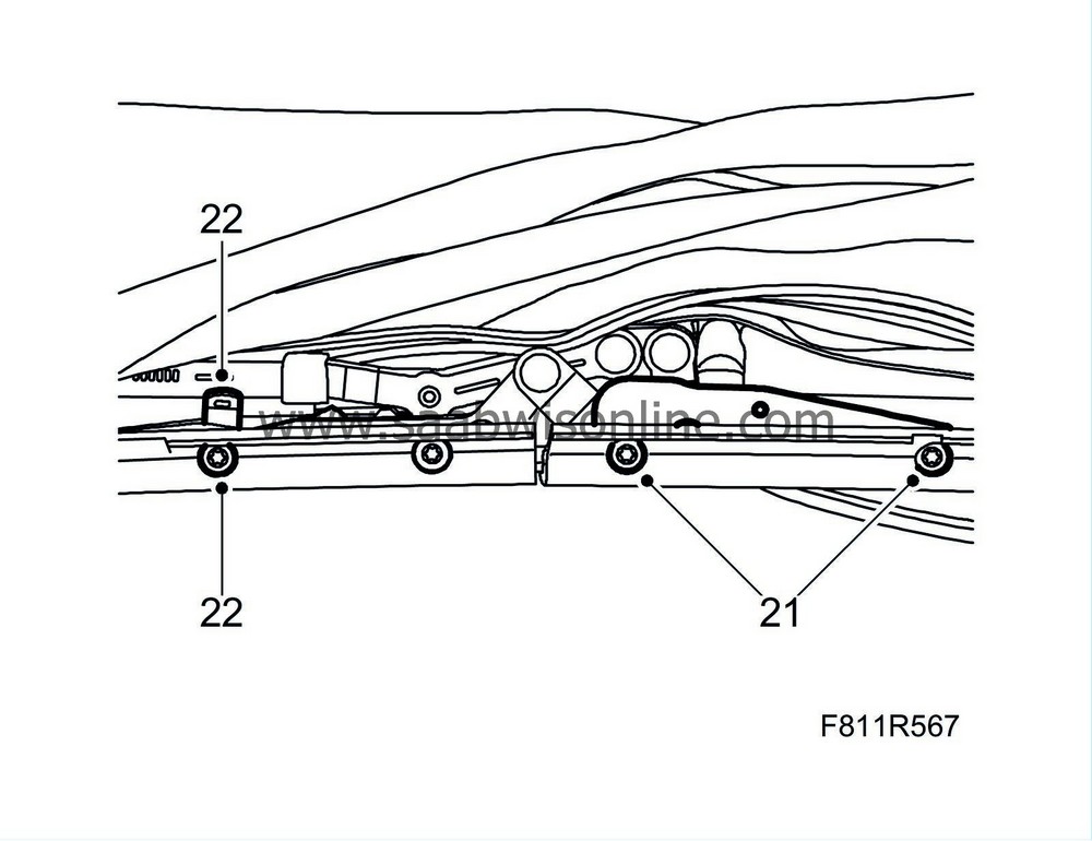
Tightening torque 23 Nm (17 lbf ft)
|
|
22.
|
Remove the screw and the bracket for the line assembly, from the centre rail.
|
|
23.
|
Align the new bracket in the correct position and fit a screw. Tighten the screw loosely.
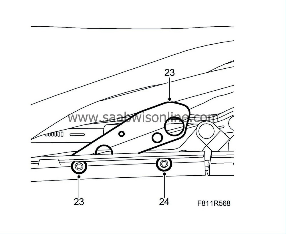
|
|
25.
|
Align the bracket in the correct position and fit a screw. Tighten the screw loosely.
|
|
26.
|
Check that the distance between the front and the centre rail is equivalent to the measurement noted down earlier in step 12. If necessary, adjust the rail so that the distance is correct.
|
|
27.
|
Tighten both of the screws for the bracket.
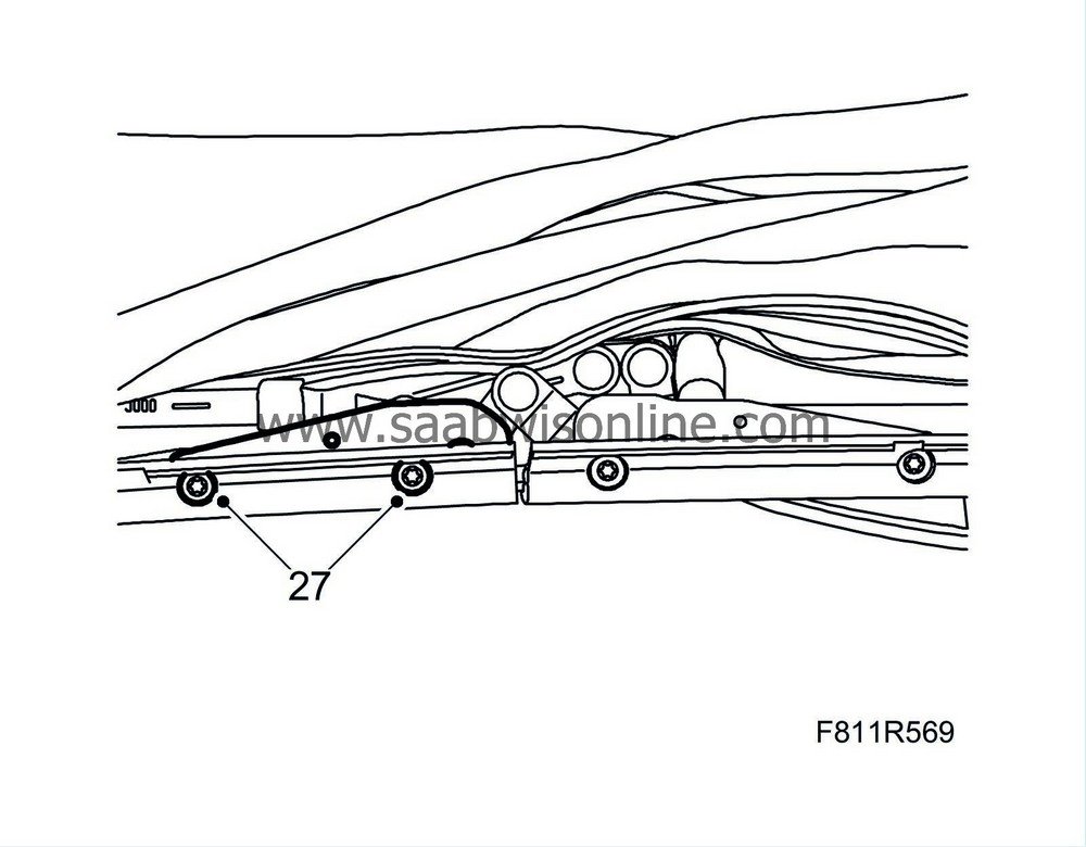
Tightening torque 23 Nm (17 lbf ft)
|
|
28.
|
Check that none of the lines are damaged.
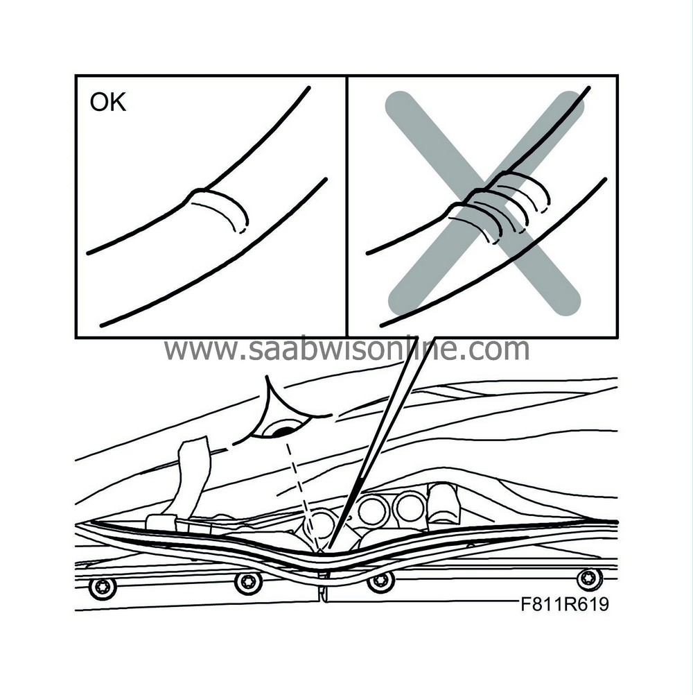
|
|
|
28.a.
|
If the lines are not defective or only have one bend, continue with step 29.
|
|
|
28.b.
|
If any of the lines is damaged and has more than one bend, replace the whole line assembly, in accordance with "Replacing the hydraulic lines and wiring harness, front bow" in these instructions.
|
|
29.
|
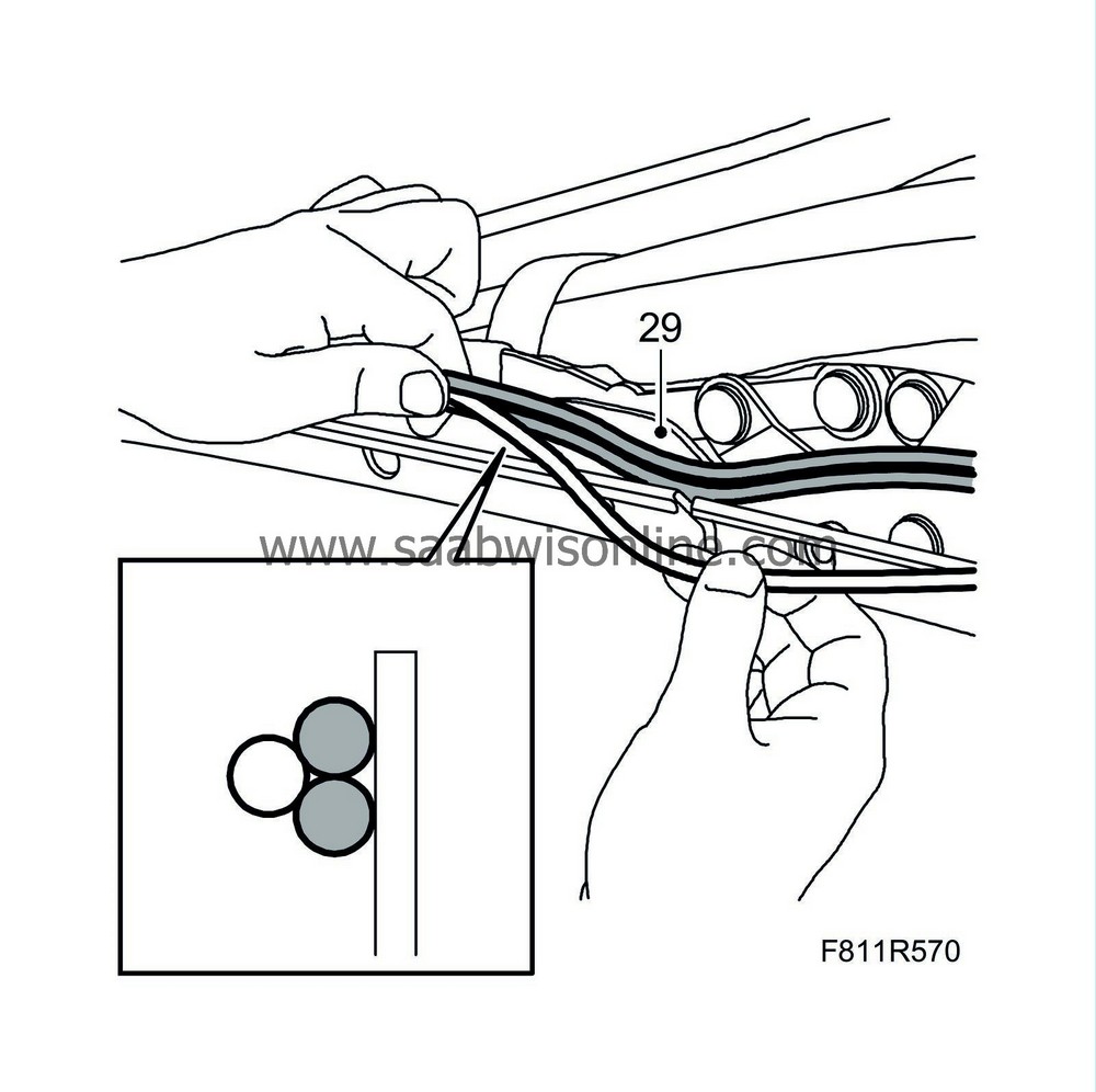
Untwist the line assembly and position the two hydraulic lines (grey) closest to the brackets with the electrical cable (white) on the outside of the hydraulic lines. The line assembly must be shaped like a triangle with the electrical cable on the outside, see illustration.
|
Note
|
|
Th electrical cable has a smoother surface than the hydraulic lines.
|
|
|
30.
|
Secure the line assembly in the brackets with cable ties, tighten loosely. Fit the cable ties so that their heads are located uppermost on top of the line assembly.
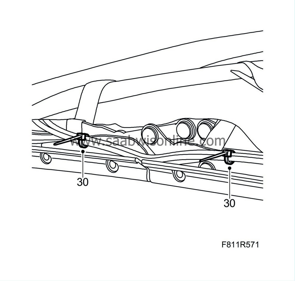
|
|
31.
|
Fit the enclosed fitting tool and position the line assembly on the top of the tool.
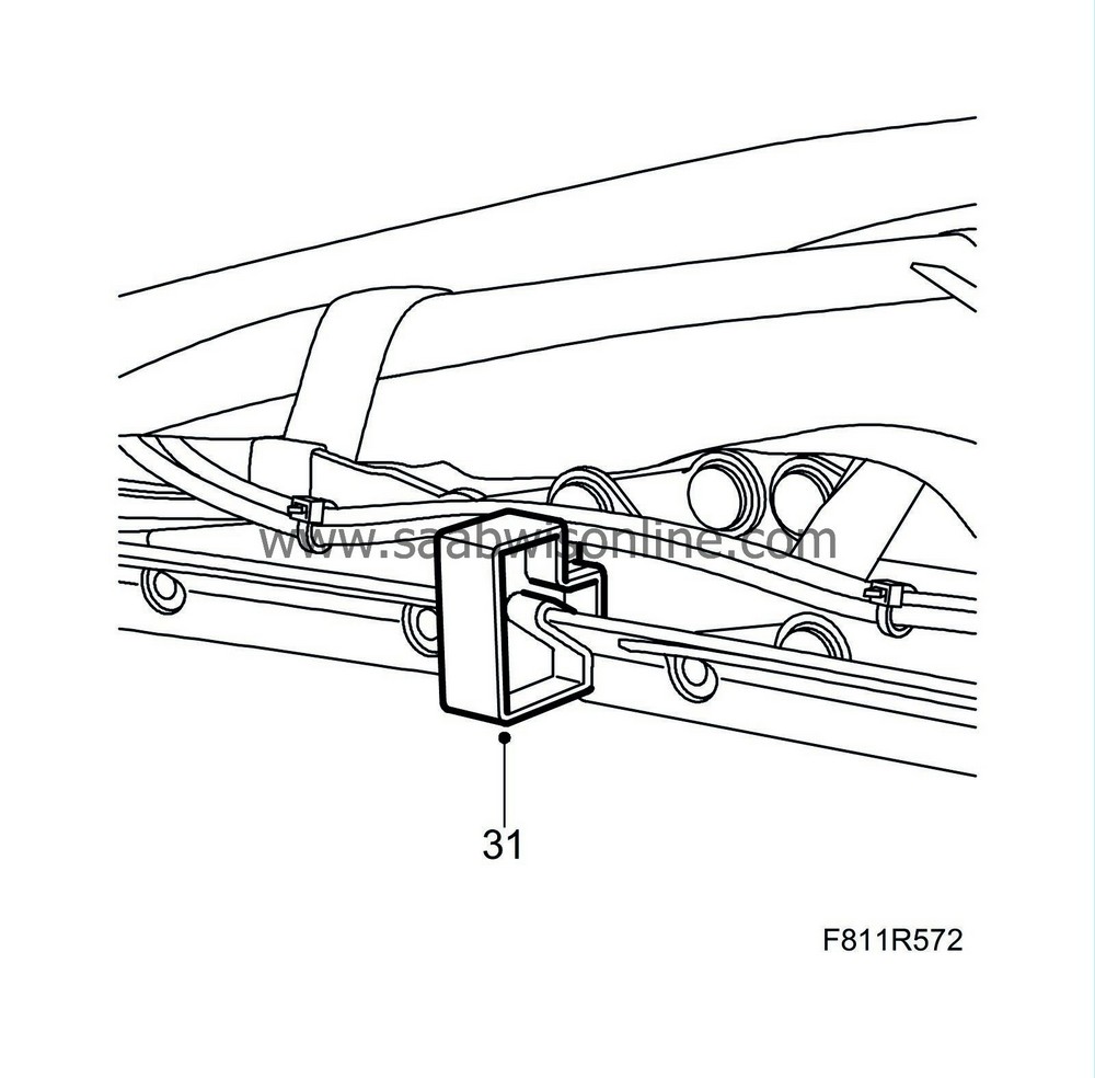
|
|
32.
|
Tighten the cable ties and cut off any cable tie excess.
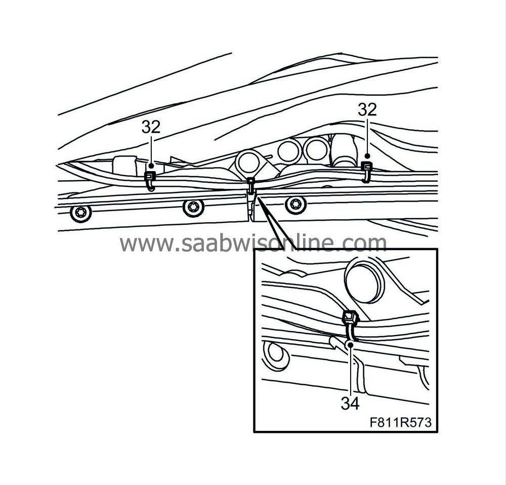
|
|
33.
|
Remove the fitting tool.
|
|
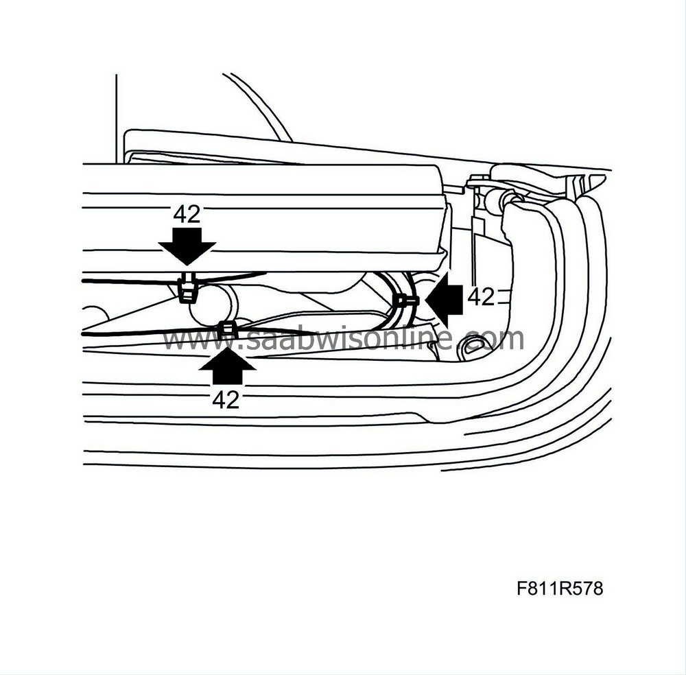
34.
|
Fit a small cable tie in the position between the centre and front rail.
|
|
35.
|
Operate the soft top to its centre position, the soft top first bow must point straight up.
|
|
36.
|
Fit the outer roof on the right-hand side of the first bow.
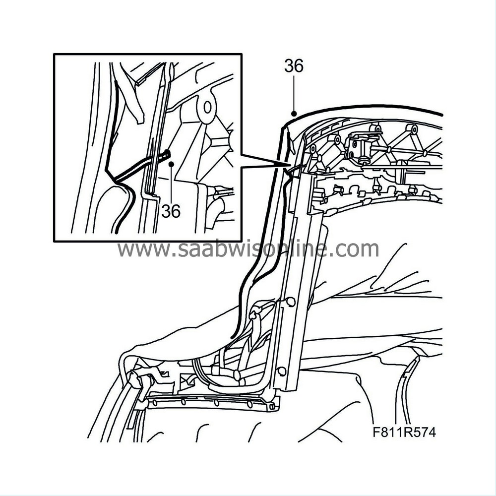
|
|
37.
|
Fit the centre rail seal.
|
|
38.
|
Fit the screw and the seal to the front rail.
|
|
39.
|
Lower the soft top and allow the soft top cover to be open.
|
|
40.
|
Fit the headlining plastic plugs and hook in the outer roof attachment eye on the right-hand side of the first bow.
|
|
41.
|
Fit the headlining attachment eyes to the first bow on the right-hand side.
|
|
42.
|
Operate the soft top to check that the line assembly does not get trapped or twist.
|
|
43.
|
Operate the soft top for 5 complete cycles in order to bleed the system and check the function. Check that the lines are positioned correctly and that there is no risk of them becoming trapped in the hinges.
|
|
44.
|
After replacement of hydraulic lines:
Fill with oil in the reservoir to the MAX mark, see WIS 8. Body - Hood system - Adjustment/Replacement - Checking/filling oil.
|
|
45.
|
After replacement of hydraulic lines:
Check that there is no leakage of oil at any point.
|
|
46.
|
Lower the soft top and allow the soft top cover to be open.
|
|
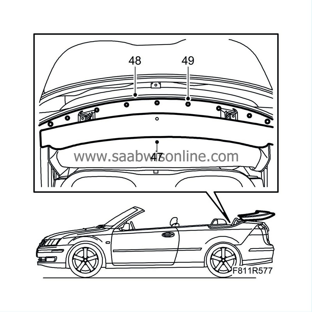
47.
|
Fit the trim.
|
|
48.
|
Fit the mounting plate with the clips.
|
|
49.
|
Fit the clips' centre pins to the mounting plate.
|
|
50.
|
Raise the soft top fully.
|
|
51.
|
Connect the diagnostic tool and clear any diagnostic trouble codes.
|
Replacing the hydraulic lines and wiring harness, front bow
To remove
|
1.
|
Raise the soft top fully.
|
|
2.
|
Remove the luggage compartment side trim on the right-hand side, see WIS - 8. Body - Interior equipment - Adjustment/Replacement - Luggage compartment trim, CV.
|
|
3.
|
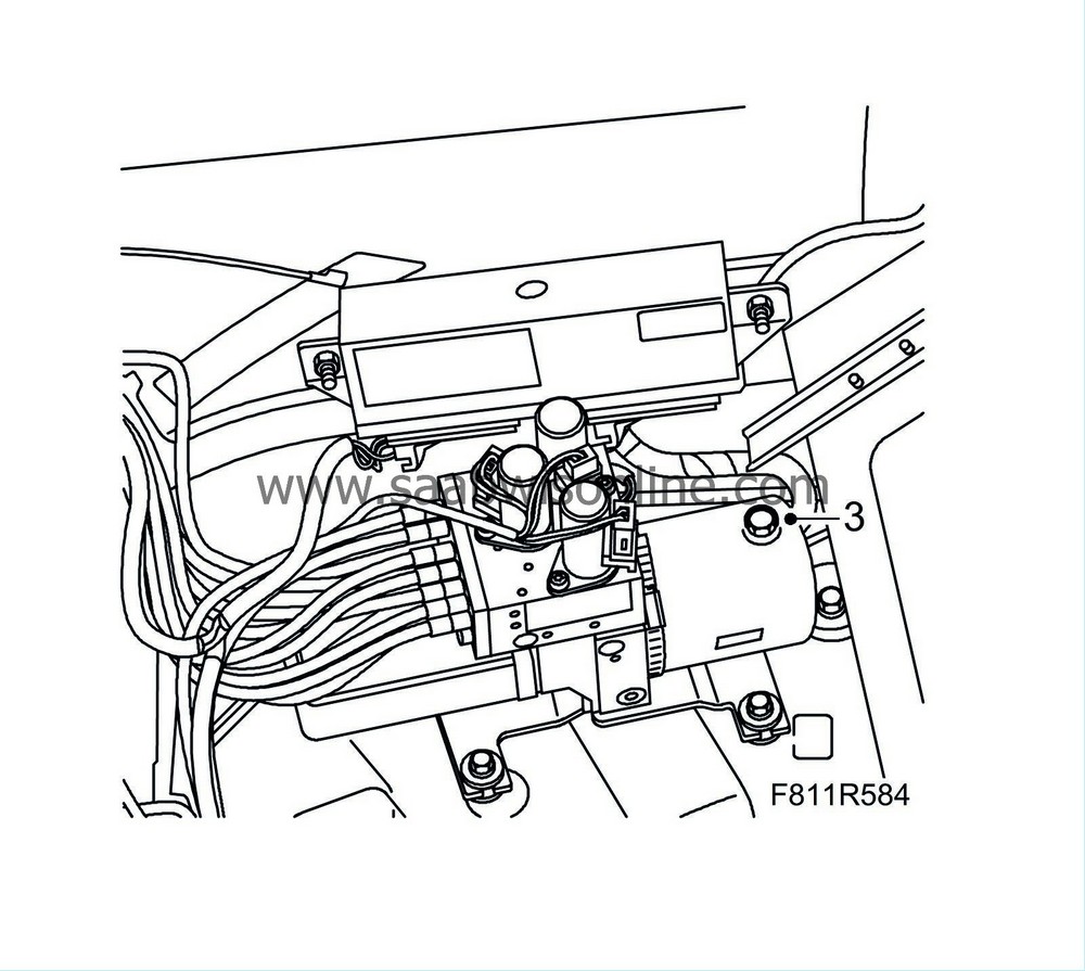
Remove the oil filler plug (for pressure equalisation). Refit the plug.
|
|
4.
|
Lower the soft top and allow the soft top cover to be up.
|
|
5.
|
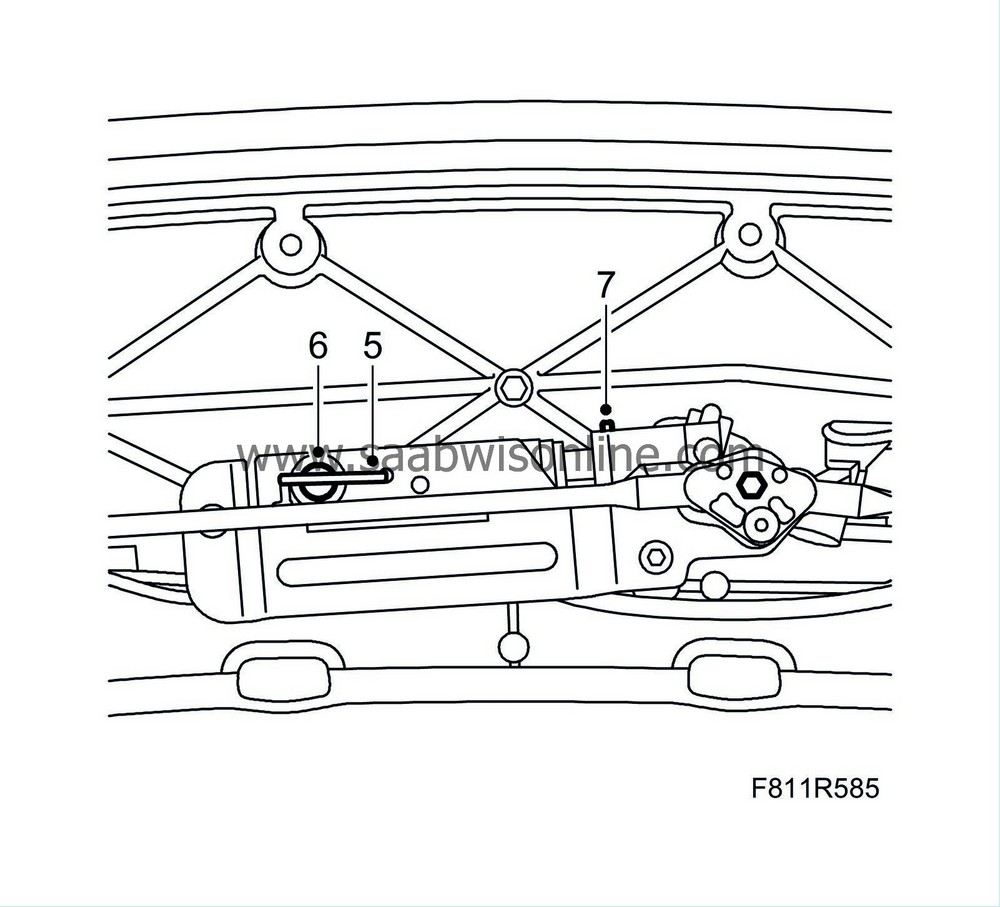
Turn the locking hook so that the cable lock and the fastening pin for the hydraulic cylinder are accessible.
|
|
6.
|
Remove the clip to the hydraulic cylinder piston rod.
|
|
7.
|
Unhook the cable lock from the fastening pin.
|
|
8.
|
Pull out the hydraulic cylinder fastening pin.
|
|
9.
|
Position a cloth under the cylinder to catch any hydraulic oil that may run out. Remove the hydraulic cylinder from the holder so that it is easier to access the hydraulic lines' connections.
|
|
10.
|
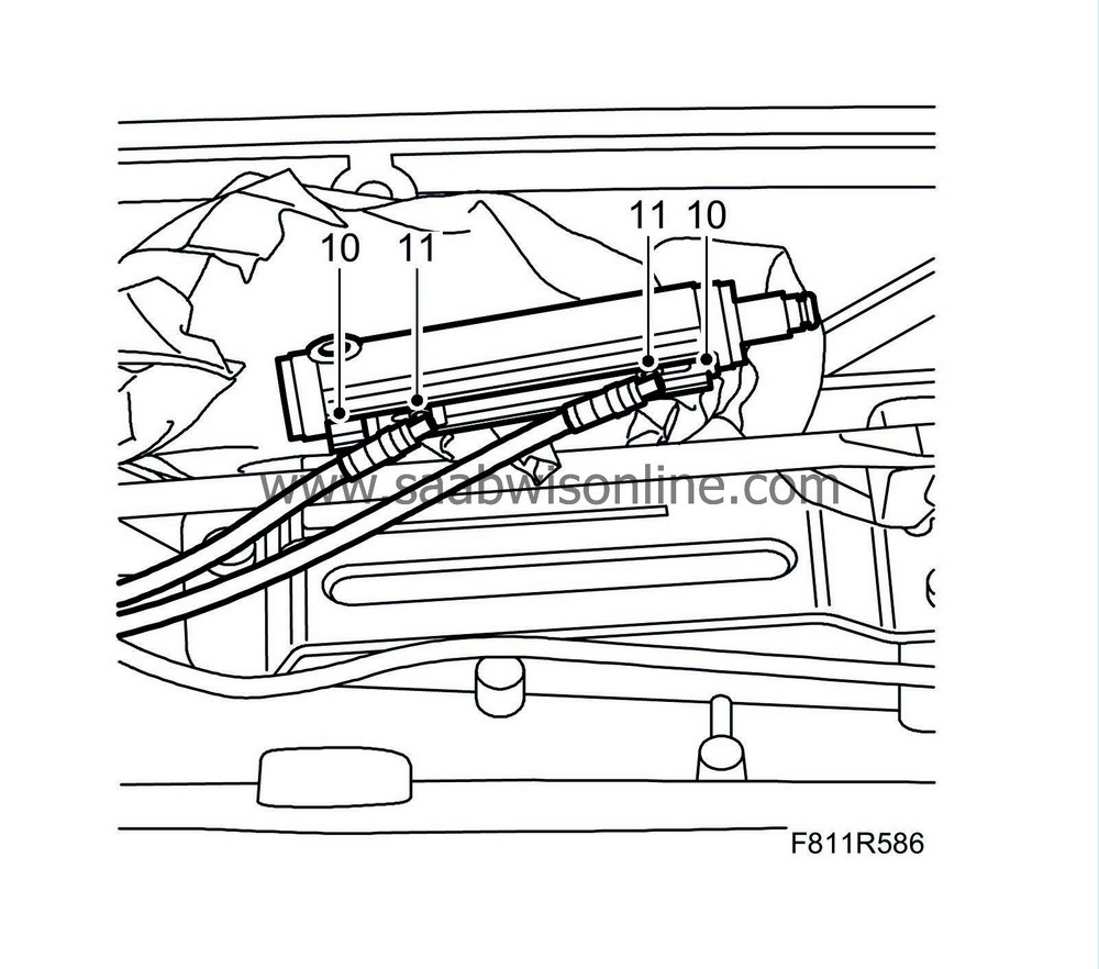
Remove the hydraulic lines' retaining clips by pulling them out.
|
|
11.
|
Pull the hydraulic lines out from the hydraulic cylinder and remove the hydraulic cylinder.
|
|
12.
|
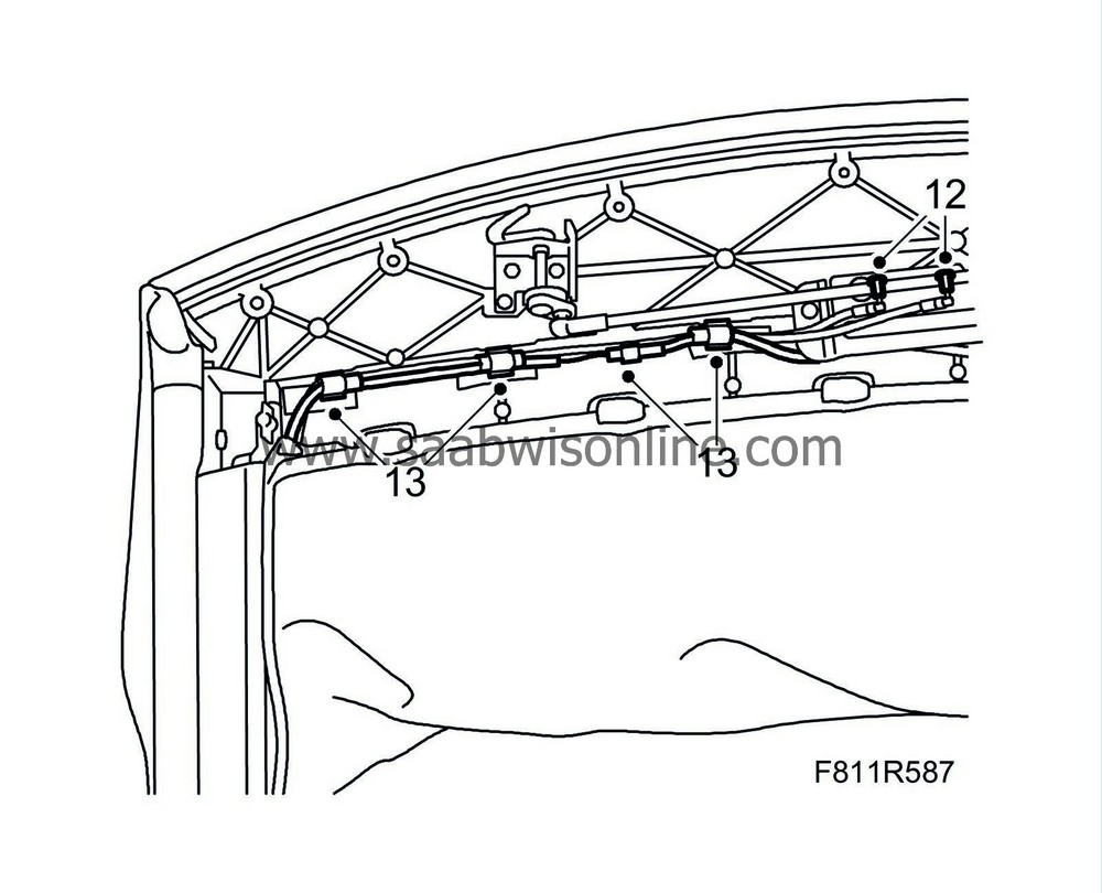
Plug the hydraulic cylinders to avoid spilling oil on the roof upholstery.
|
|
13.
|
Remove the connector and cut off the cable ties, thread the hydraulic lines and the wiring harness out from the first bow.
|
|
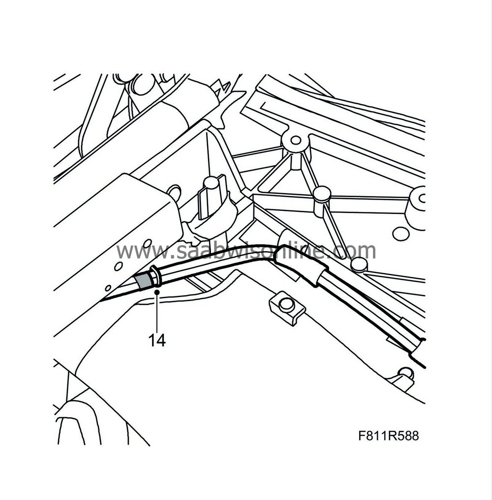
14.
|
Cut off the cable ties securing the lines.
|
|
15.
|
Raise the soft top manually.
|
|
16.
|
Remove the soft top storage, see WIS - 8. Body - Hood system - Adjustment/Replacement - Soft top storage.
|
|
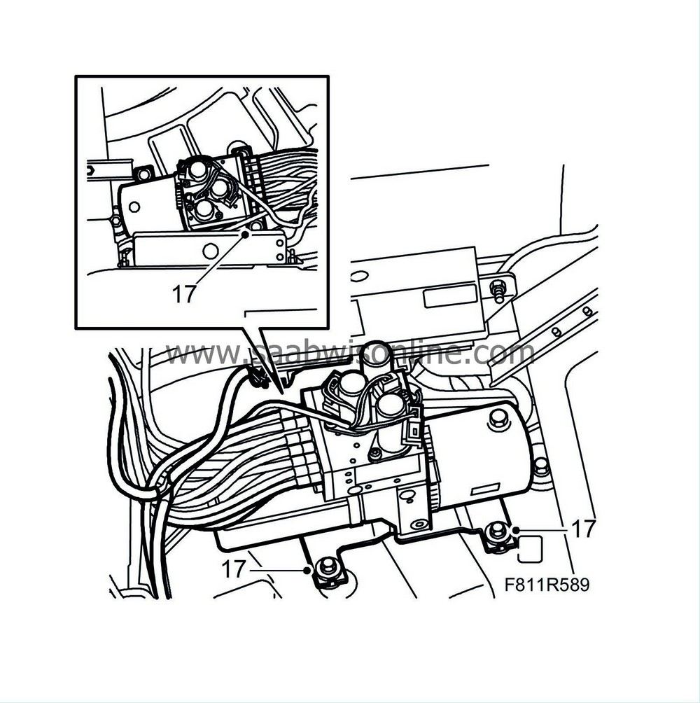
17.
|
Remove the hydraulic unit nuts and lift up the hydraulic unit slightly so that the connections are accessible.
|
|
18.
|
Position a cloth under the hydraulic unit to catch any hydraulic oil that may run out.
|
|
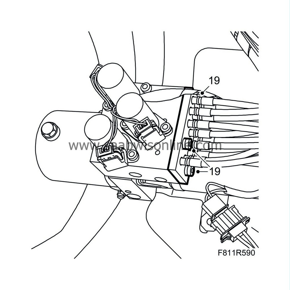
19.
|
Remove the attaching plate together with the hydraulic lines from the hydraulic unit.
|
|
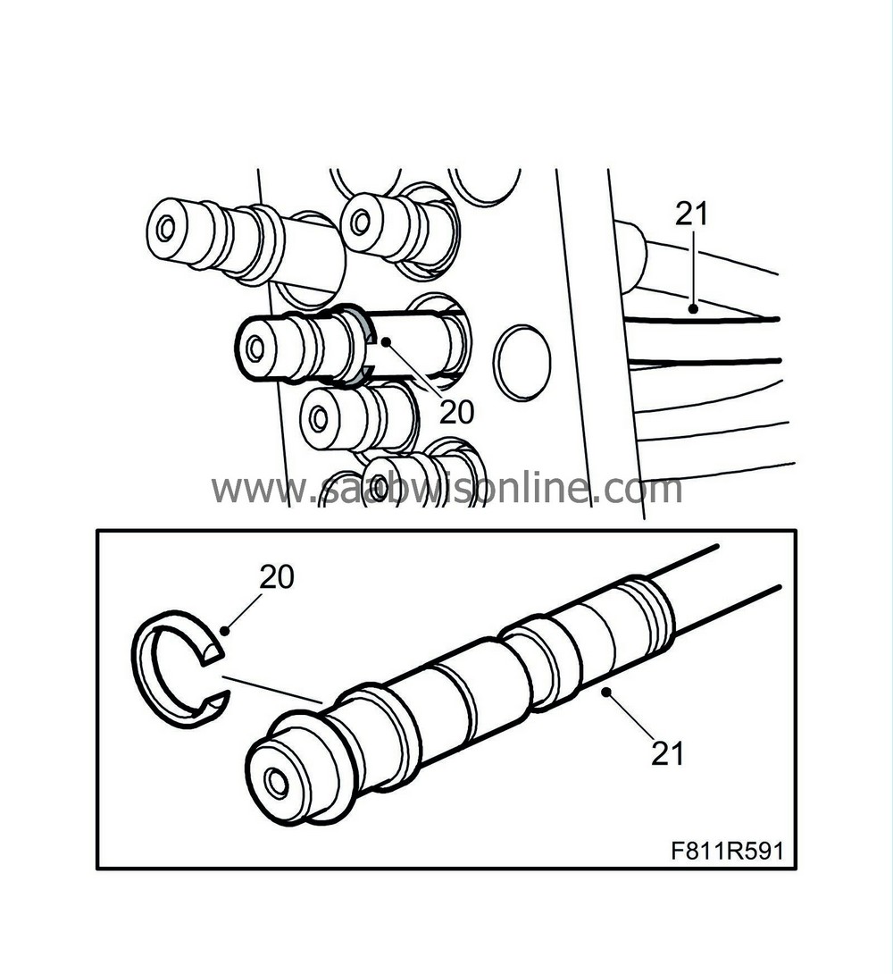
20.
|
Remove the circlip from the connecting section of the hydraulic lines (no. 65 and 66) using a small screwdriver.
|
|
21.
|
Pull the hydraulic lines out from the attaching plate.
|
|
22.
|
Remove the cable ties.
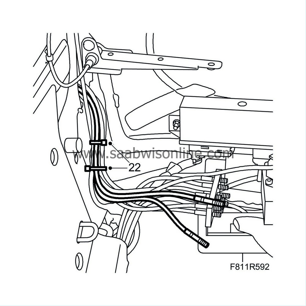
|
|
23.
|
Detach the soft top storage hinge.
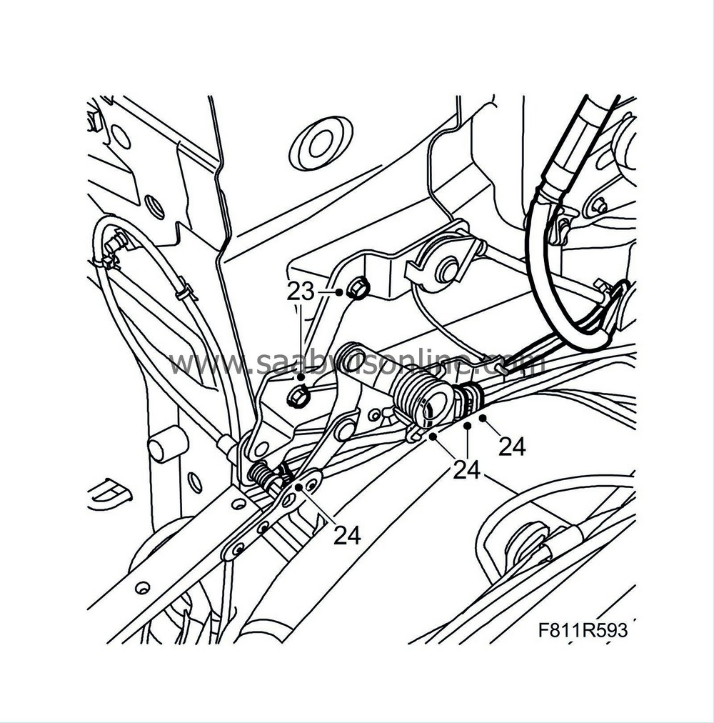
|
|
24.
|
Remove the cable ties and open the hydraulic lines' brackets.
|
|
25.
|
Lift up the line assembly and locate the electrical cables from the first bow's position sensor and cut them off close to the wiring harness taping.
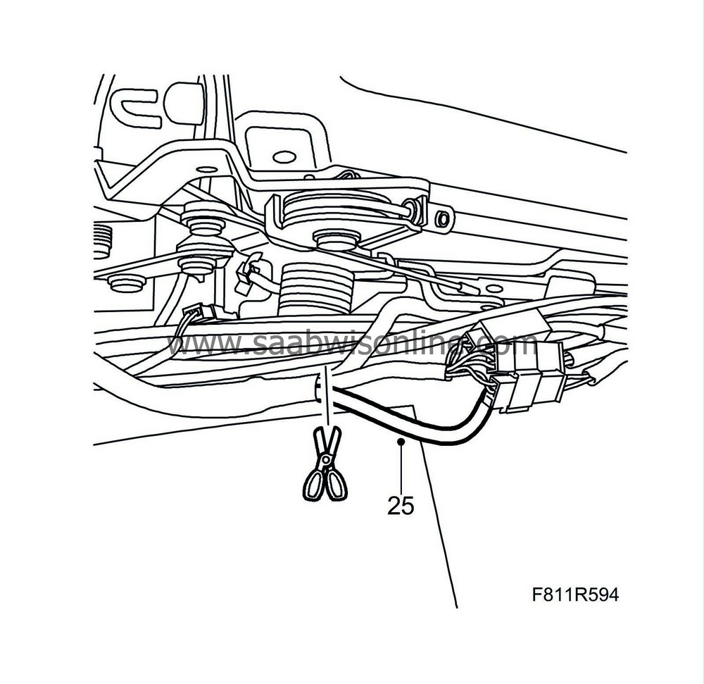
|
|
26.
|
Remove the connector (blue) from the control module.
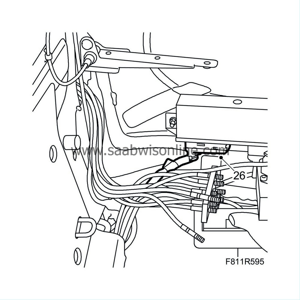
|
|
27.
|
Separate the connector.
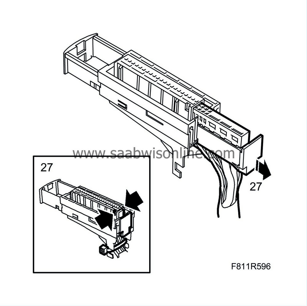
|
|
28.
|
Remove the tape close to the connector so that the cables are exposed.
|
|
29.
|
Extract sleeve 21 (brown) and sleeve 12 (black).
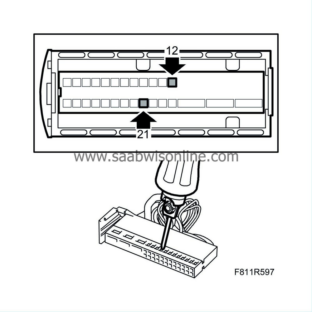
|
|
30.
|
Cut off the extracted and exposed cables close to the tape.
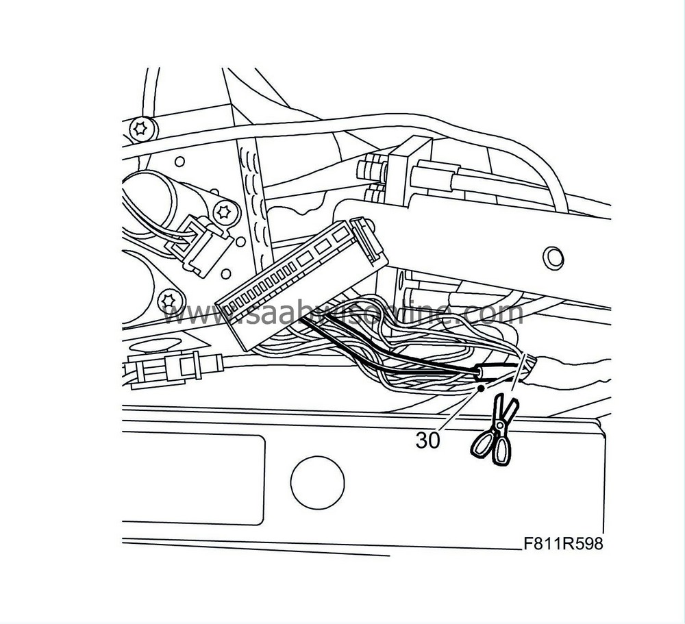
|
|
31.
|
Note down the routing and attachment points for the cables.
|
|
32.
|
Remove the clip.
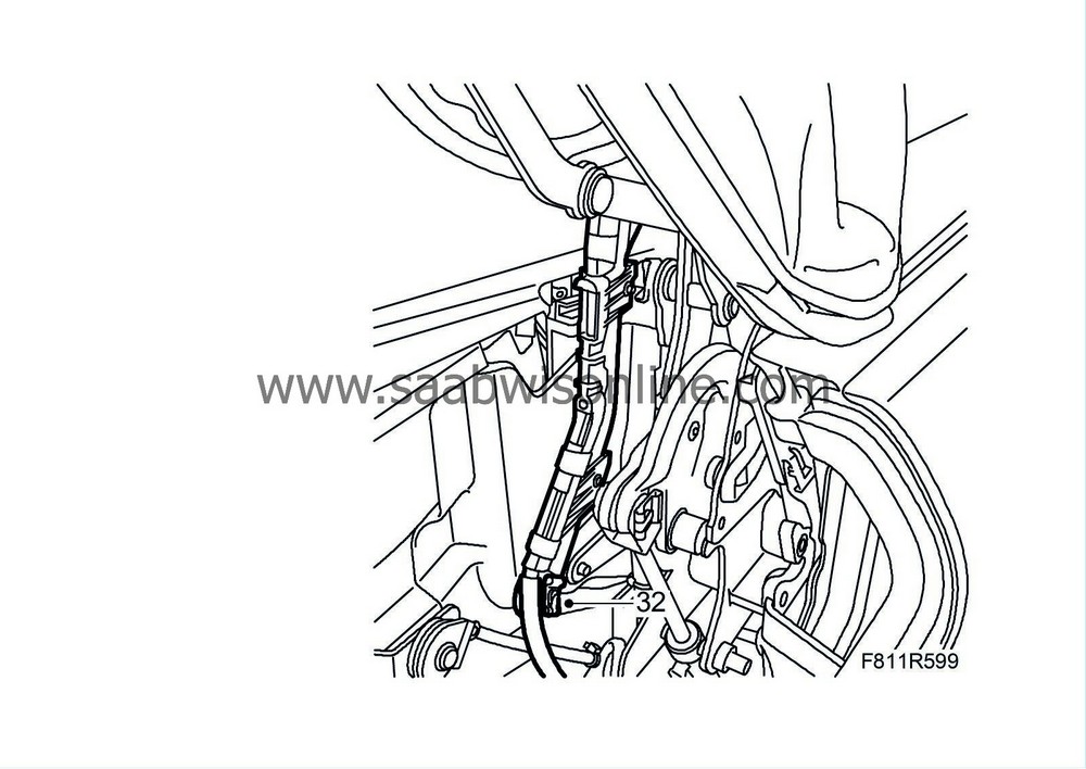
|
|
33.
|
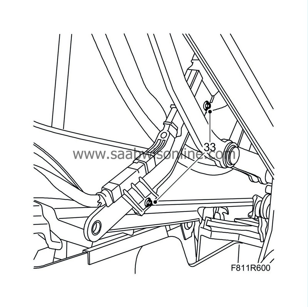
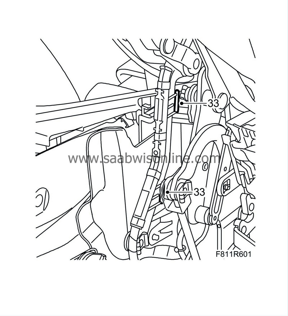
Cars up to and including VIN 46001629:
Remove the blind rivets and remove the cable duct from the hinge.
Cars from and including VIN 46001630:
Remove the clips and remove the cable duct from the hinge.
|
|
34.
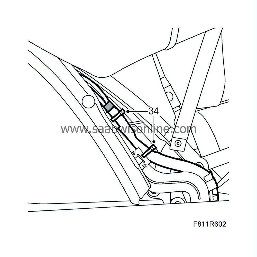
|
Detach the right-hand corner of the headlining and cut off the cable ties holding the cables to the metal clips.
|
|
35.
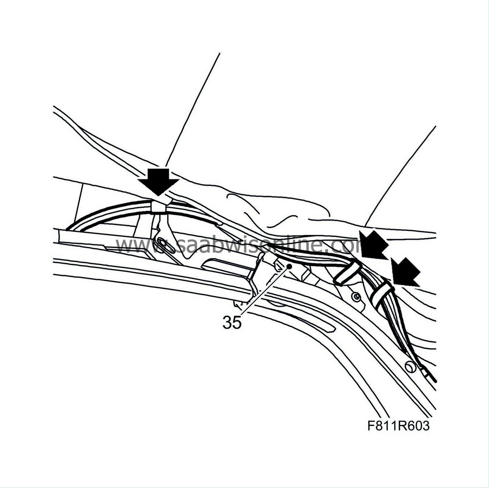
|
Carefully thread the line assembly backward from the soft top eyes.
|
To fit
|
1.
|
Carefully thread the lines through the soft top eyes.
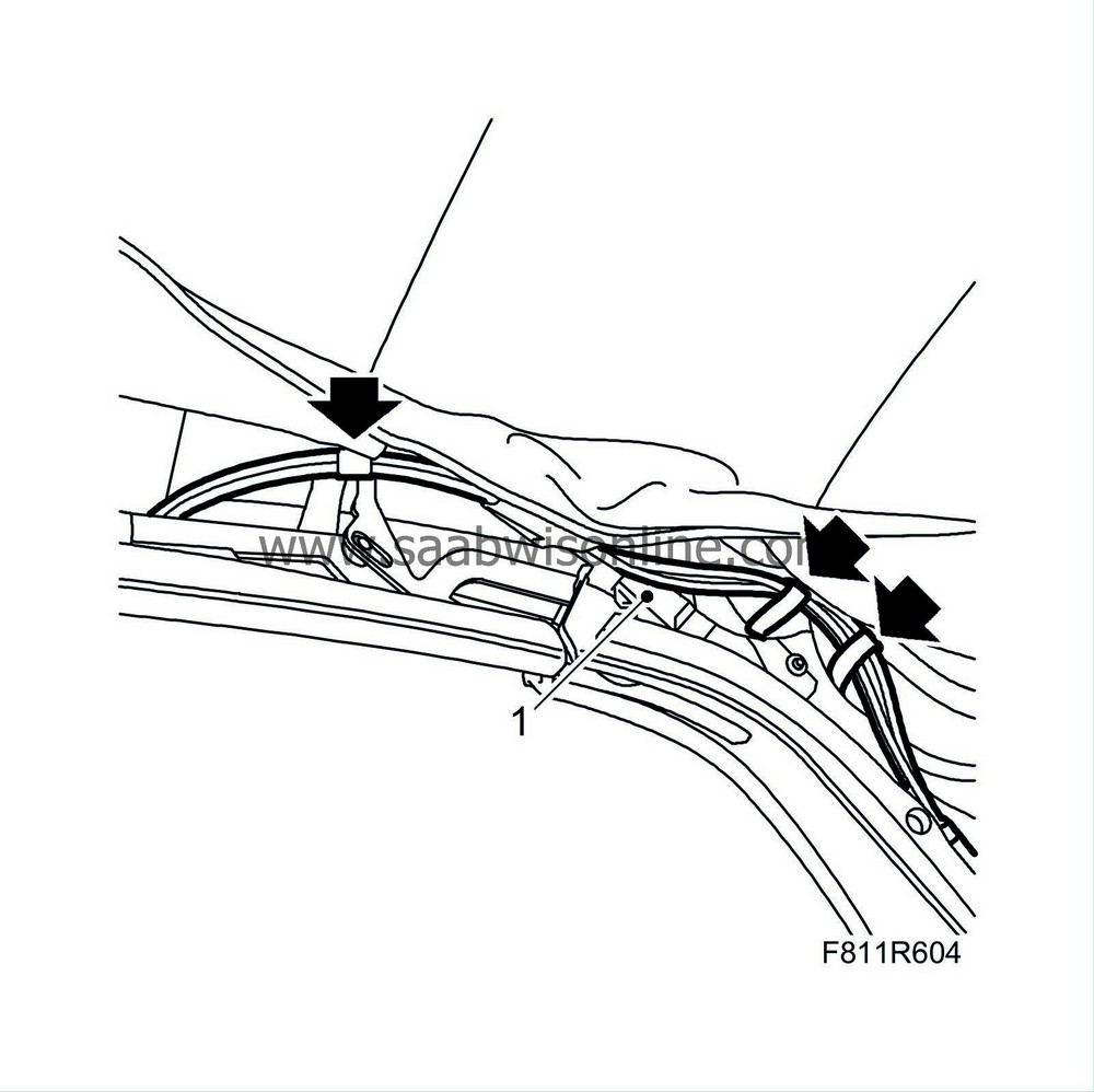
|
|
2.
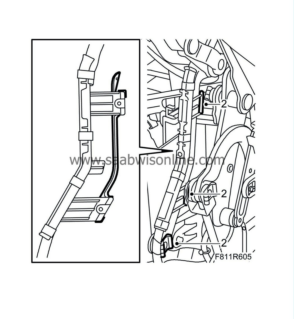
|
Secure the cable duct to the hinge with clips and refit the hinge's metal clips.
|
|
3.
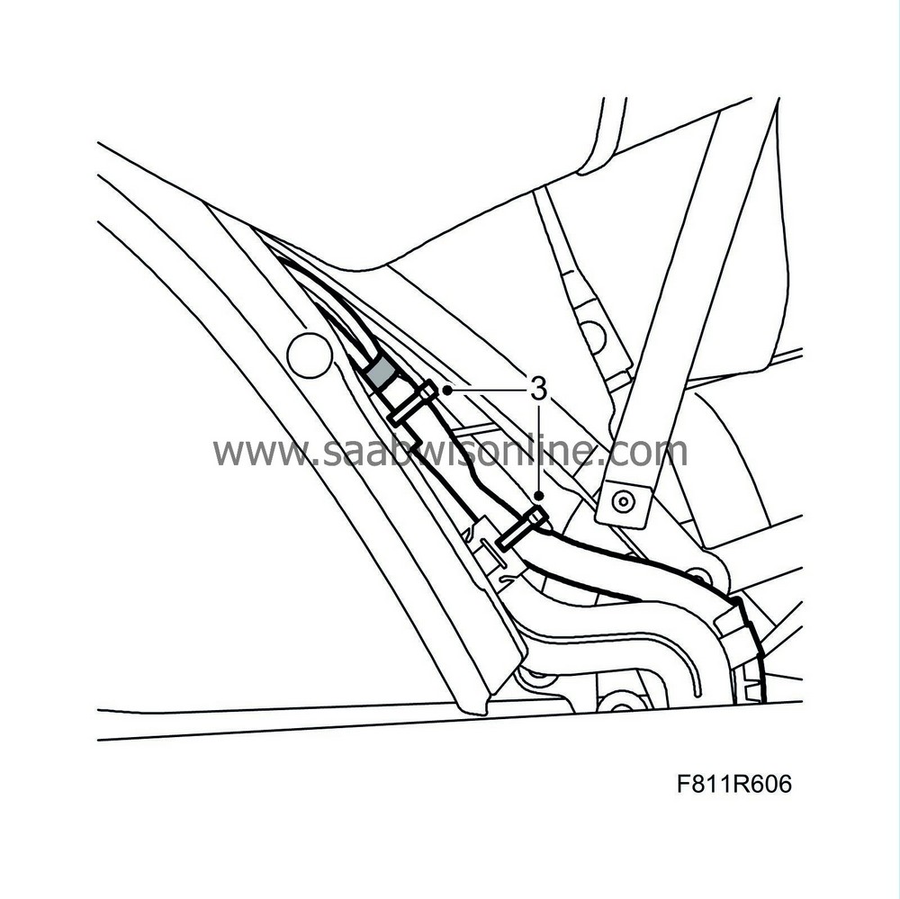
|
Fit chafe protection tape and secure the lines with new cable ties in the metal clips.
|
|
4.
|
Fit the headlining right-hand corner.
|
|
5.
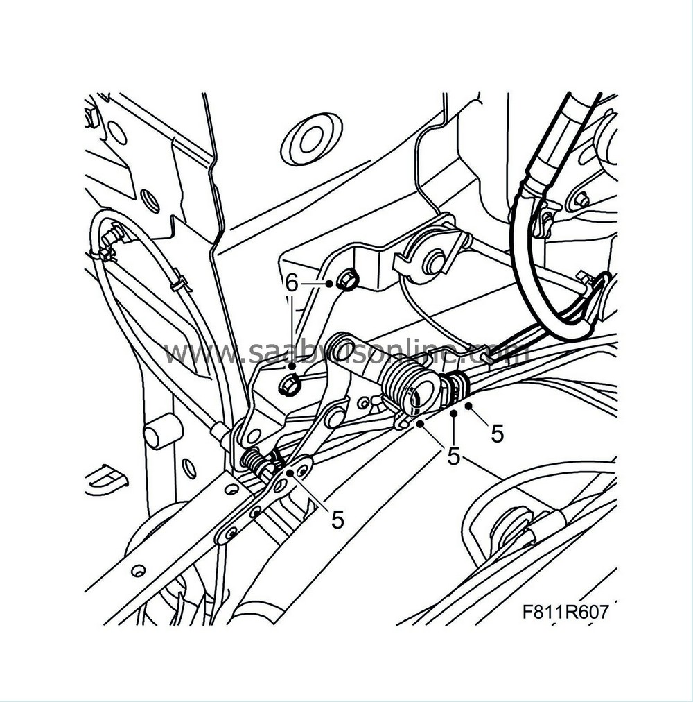
|
Fit the lines in place and secure them with new cable ties.
|
|
6.
|
Fit the soft top storage hinge.
|
|
7.
|
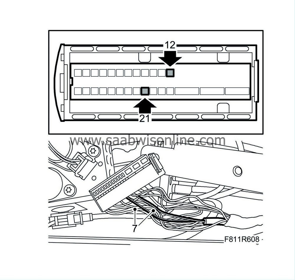
Fit sleeve 21 (brown) and sleeve 12 (black) in the connector.
|
|
8.
|
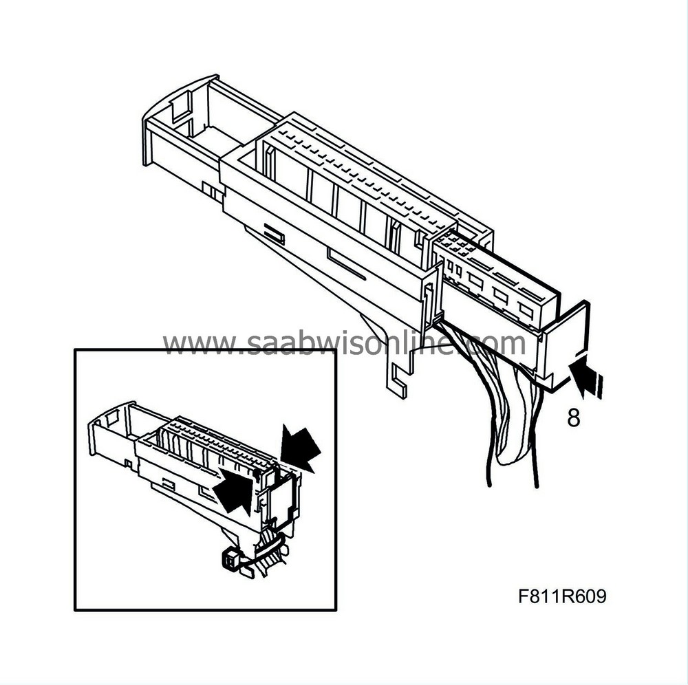
Plug the connector together.
|
|
9.
|
Tape the exposed cables close to the connector.
|
|
10.
|
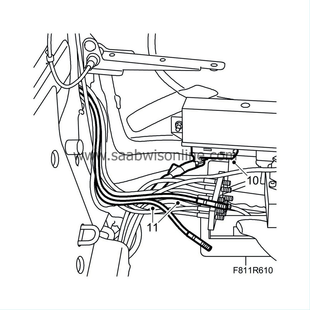
Plug the connector into the control module.
|
|
11.
|
Insert the new hydraulic lines in the attaching plate in position no. 65 and 66.
|
|
12.
|
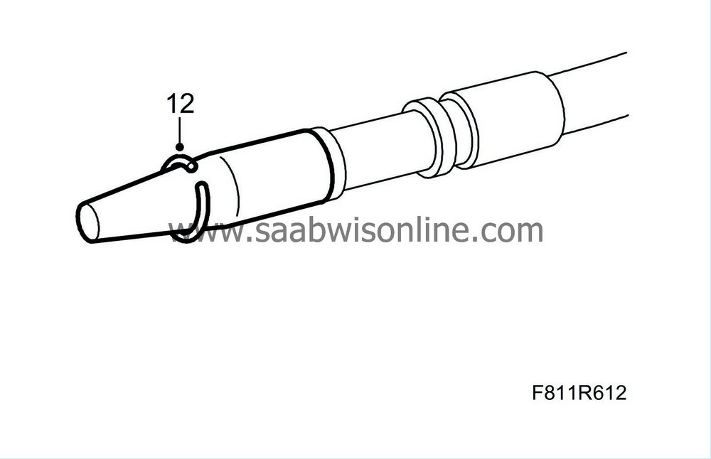
Fit new circlips to the two new hydraulic lines:
|
|
|
-
|
Press on the special tool, 82 93 854 Fitting tool, hydraulic line, over the connection for the hydraulic line.
|
|
|
-
|
Fit the circlip on the special tool's cone. Press it over the flange on the line.
|
|
13.
|
Fit new O-rings on the new hydraulic lines:
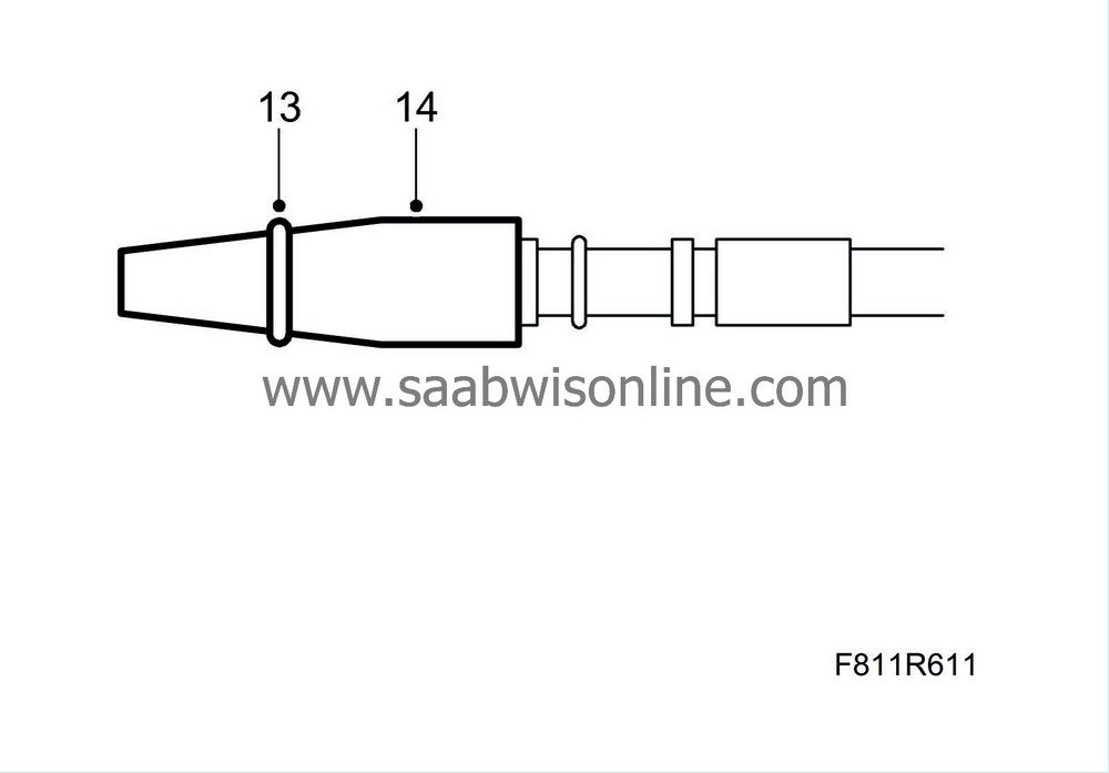
|
|
|
-
|
Press on the special tool, 82 93 854 Fitting tool, hydraulic line, over the connection for the hydraulic line.
|
|
|
-
|
Fit the O-ring on the special tool's cone and fit the O-ring on the hydraulic line.
|
|
14.
|
Remove the special tool.
|
|
15.
|
Align the attaching plate together with the hydraulic lines in the fitting position.
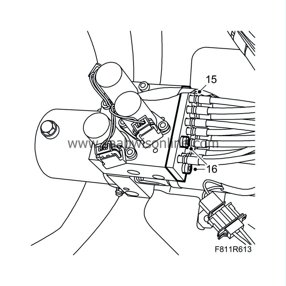
|
|
16.
|
Fit and tighten the screws to the hydraulic lines' attaching plate.
|
|
17.
|
Wipe away any spilled oil.
|
|
18.
|
Align the hydraulic unit in the fitting position and fit the hydraulic unit's nuts.
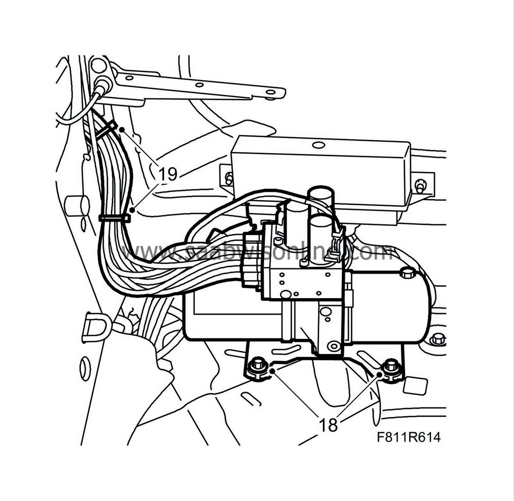
|
|
19.
|
Secure the lines with cable ties.
|
|
20.
|
Fit the soft top storage, see WIS - 8. Body - Hood system - Adjustment/Replacement - Soft top storage.
|
|
21.
|
Fit the connector and secure the lines with cable ties.
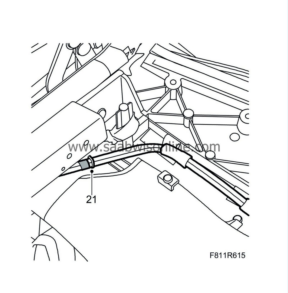
|
|
22.
|
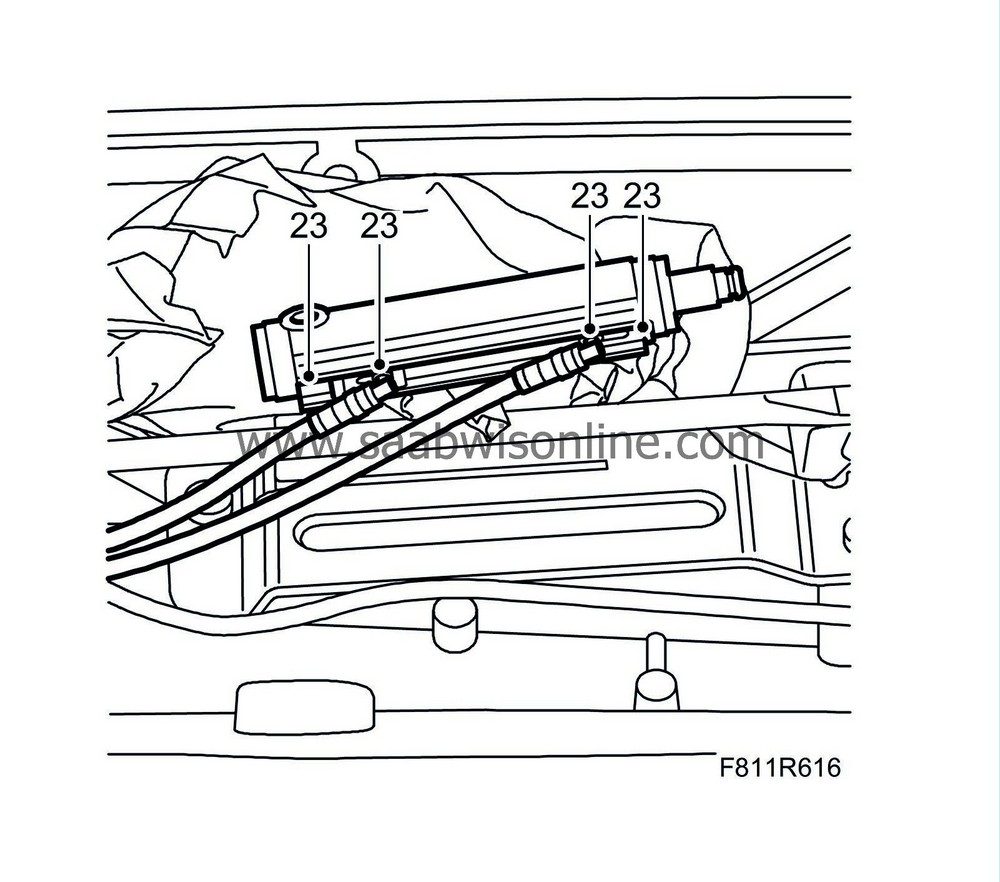
Replace the O-rings at the hydraulic cylinder's connections with new ones.
|
|
23.
|
Fit the hydraulic lines on the hydraulic cylinder by pressing them in. Take care so as not to damage the seal.
|
|
24.
|
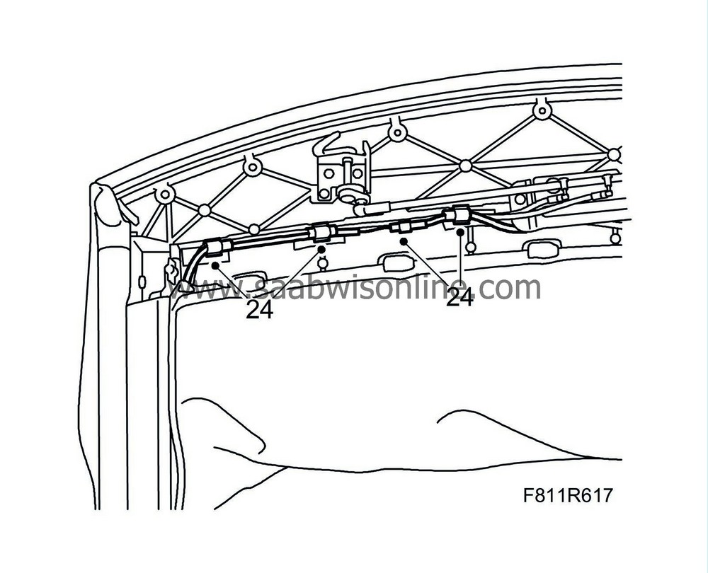
Fit the chafe protection tape on the line assembly and fit the line assembly clips.
|
|
25.
|
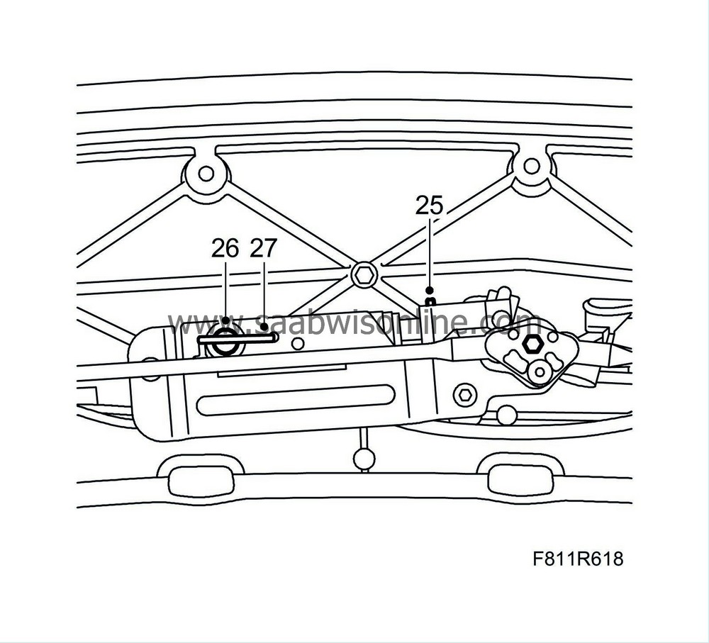
Align the hydraulic cylinder in the fitting position. Fit the clip to the hydraulic cylinder piston rod.
|
|
26.
|
Fit the hydraulic cylinder fastening pin.
|
|
27.
|
Fit the cable lock to the fastening pin.
|
|
28.
|
Turn the locking hooks so that they open.
|
|
29.
|
Continue with step 29 in the section "Checking, securing and, if necessary, replacement of hydraulic lines".
|
C. Updating the STC/BCM software
|
1.
|
Cars with VIN up to and including 46008095:
Select "ECU-information" for the BCM and read off which software the BCM has.
|
|
|
-
|
If the BCM has software with part no. 12805077, continue with step 2 below.
|
|
|
-
|
If the BCM does not have software with part no. 12805077, update the software for the BCM to the latest status. USE TIS2000, version 2004-6 update 2 or later.
|
|
2.
|
All cars:
Select "ECU-information" for the STC and read off which software the STC has.
|
|
|
-
|
If the STC has software with part no. 12763966 then no action is necessary.
|
|
|
-
|
If the STC does not have software with part no. 12763966, update the software for the STC to the latest status. USE TIS2000, version 2004-6 update 2 or later.
|
|
Marking the modification identity plate (not US/CA)
|
After carrying out the procedure, box B5 on the modification identity plate must be marked. From and including M04 the table "Table of Modifications" can be found in the car's Warranty and Service Book. Mark the box with the number "7" if the procedure was carried out by the importer or with the number "8" if carried out by the dealer.
|
Fitting the modification identity plate (not US/CA)
|
|
Note
|
|
A modification identity plate must only be fitted where local directives require the marking of the car.
|
Fit the modification identity plate in accordance with WIS - 9-3 (9440) - M04 - General - General - Technical data - Plates and labels.
|
Warranty/Time Information
|
See separate information.


