|
No.
|
Name
location
|
Illus.
|
|
|
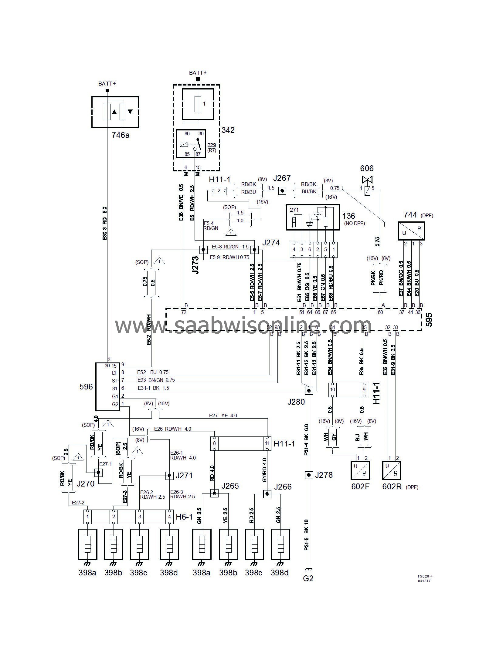
Components
|
|
|
136
|
Oxygen sensor,
|
|
|
229
|
Main relay, engine control system
in engine bay electrical centre 342
|

|
|
271
|
Heated oxygen sensor element,
integrated in the oxygen sensor
|
|
|
342
|
Underhood electrical centre 342 (UEC)
,
next to the battery
|
1
|
|
398a
|
Glow plug, cylinder 1,
on upper rear section of engine
|

|
|
398b
|
Glow plug, cylinder 2,
on upper rear section of engine
|

|
|
398C
|
Glow plug, cylinder 3,
on upper rear section of engine
|

|
|
398d
|
Glow plug, cylinder 4,
on upper rear section of engine
|

|
|
595
|
Control module, EDC16,
between the front spoiler and right-hand wheel housing
|
A
B
|
|
596
|
Control module, glow plug,
on the side of the battery cover
|

|
|
602F
|
Exhaust temperature sensor, front,
component:
in the inlet to the first catalytic converter
connector:
on the bracket beside the turbo
|

|
|
602R
|
Exhaust temperature sensor, rear,
component:
in the front edge of the rear catalytic converter
connector:
on the bulkhead partition below the coolant reservoir
|

|
|
606
|
EGR solenoid unit,
under the throttle body
|

|
|
744
|
Pressure sensor, exhaust system,
on the bulkhead partition below the coolant reservoir
|

|
|
|
6-pin connector
|
|
|
H6-1
|
Behind field rail
|

|
|
|
11-pin connector
|
|
|
H11-1
|
On RH side of engine by the fuel pump
|

|
|
|
Crimp connections
|
|
|
J265
|
Approx. 30 mm from branching point intake air sensor towards the engine control module
|

|
|
J266
|
Approx. 140 mm from branching point intake air sensor towards the engine control module
|

|
|
J267
|
Approx. 100 mm from connector A to the engine control module
|

|
|
J270
|
Approx. 200 mm from branching point starter motor towards the reversing light switch
|

|
|
J271
|
Approx. 100 mm from branching point starter motor towards the reversing light switch
|

|
|
J273
|
Approx. 50 mm from branching point starter motor towards the engine control module
|

|
|
J274
|
Approx. 100 mm from branching point starter motor towards the engine control module
|

|
|
J278
|
SOP:
in branching point glow plug control module
Rev.1:
Approx. 100mm from branching point electrical centre in engine bay towards reversing light switch
|

|
|
J280
|
SOP:
Approx. 90mm from branching point glow plug control module towards battery
Rev.1:
Approx. 250mm from branching point electrical centre in engine bay towards reversing light switch
|

|
|
|
Grounding points
|
|
|
G2
|
On the side of the left structure strut by the connector bracket
|

|


