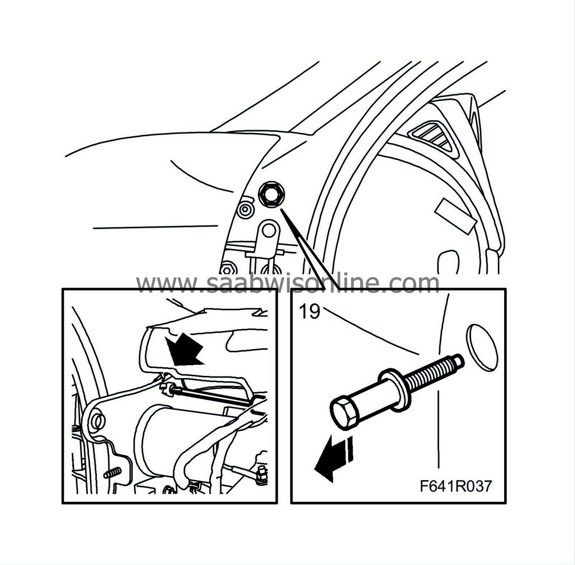
Steering wheel member
| Steering wheel member |
| Important | ||
|
The optic cables must be handled carefully so as not to distort the signal. |
||
| • |
It is extremely important that the two leads in the connector are not mixed up.
|
|
| • |
The cables cannot be spliced.
|
|
| • |
The lead must not be bent to form a curve with a radius of less than 25 mm.
|
|
| • |
The lead must not be subjected to temperatures greater than 185°F (85°C).
|
|
| • |
The lead ends should be kept free from dirt.
|
|
| • |
The lead must not be subjected to blows that could cause the transparent plastic to whiten, thereby reducing light intensity. This could cause disruptions in communication.
|
|
| • |
The lead should not be stretched across a sharp edge, which would cause increased damping of the signal.
|
|
| To remove |
| 1. |
Remove the
instrument panel
.
|
|
| 2. |
Remove
steering column assembly
.
|
|
| 3. |
Remove the bolts holding the pedal bracket to the steering wheel member.
Undo the pedal wiring connector. 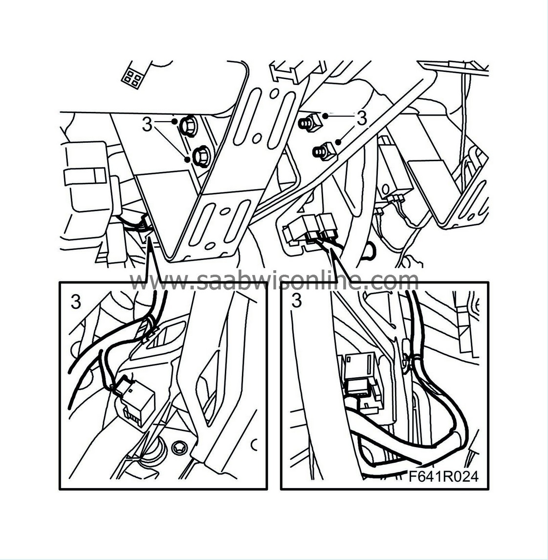
|
|
| 4. |
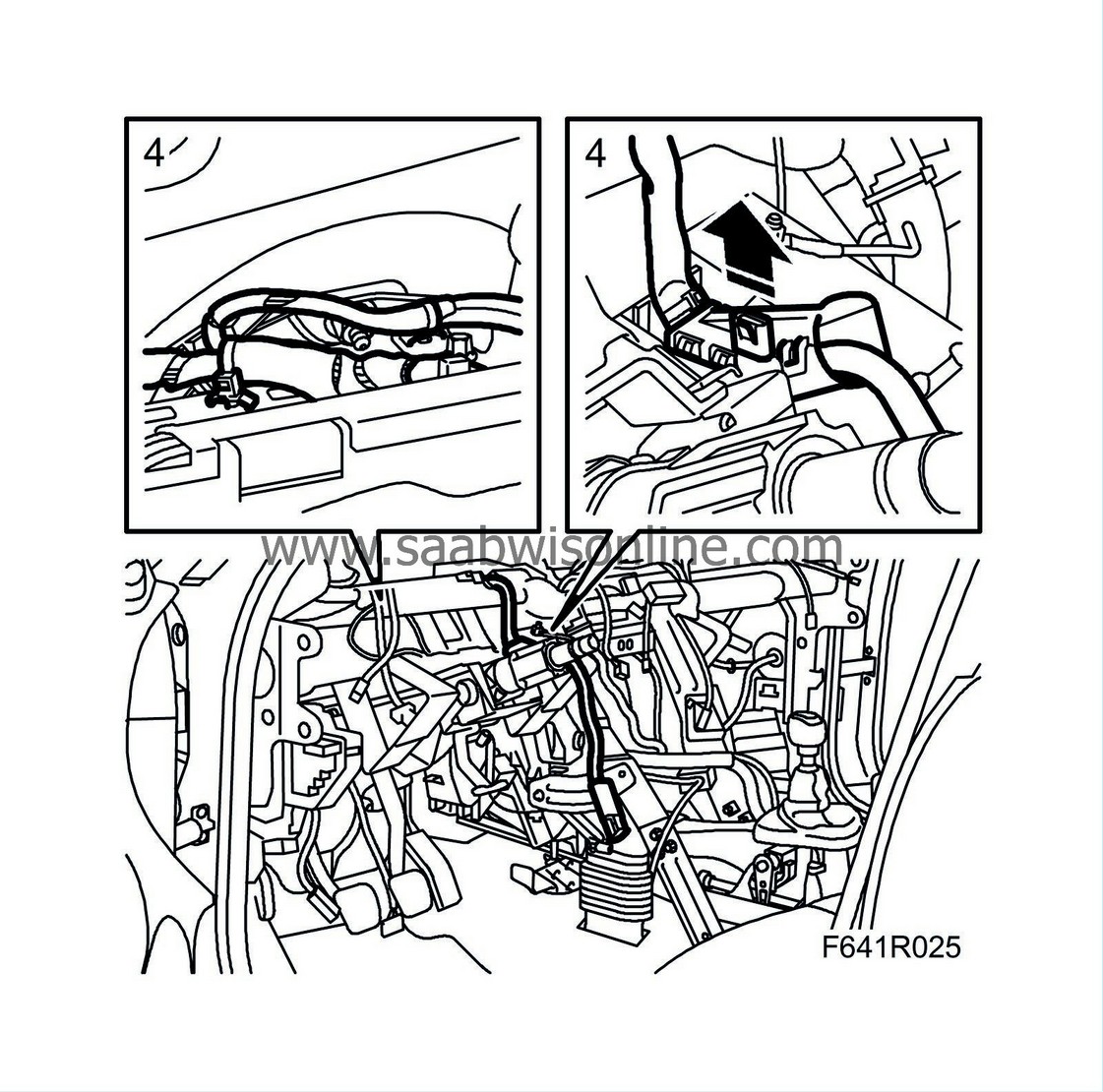
Undo the clip which holds the wiring harness.
|
|
| 5. |
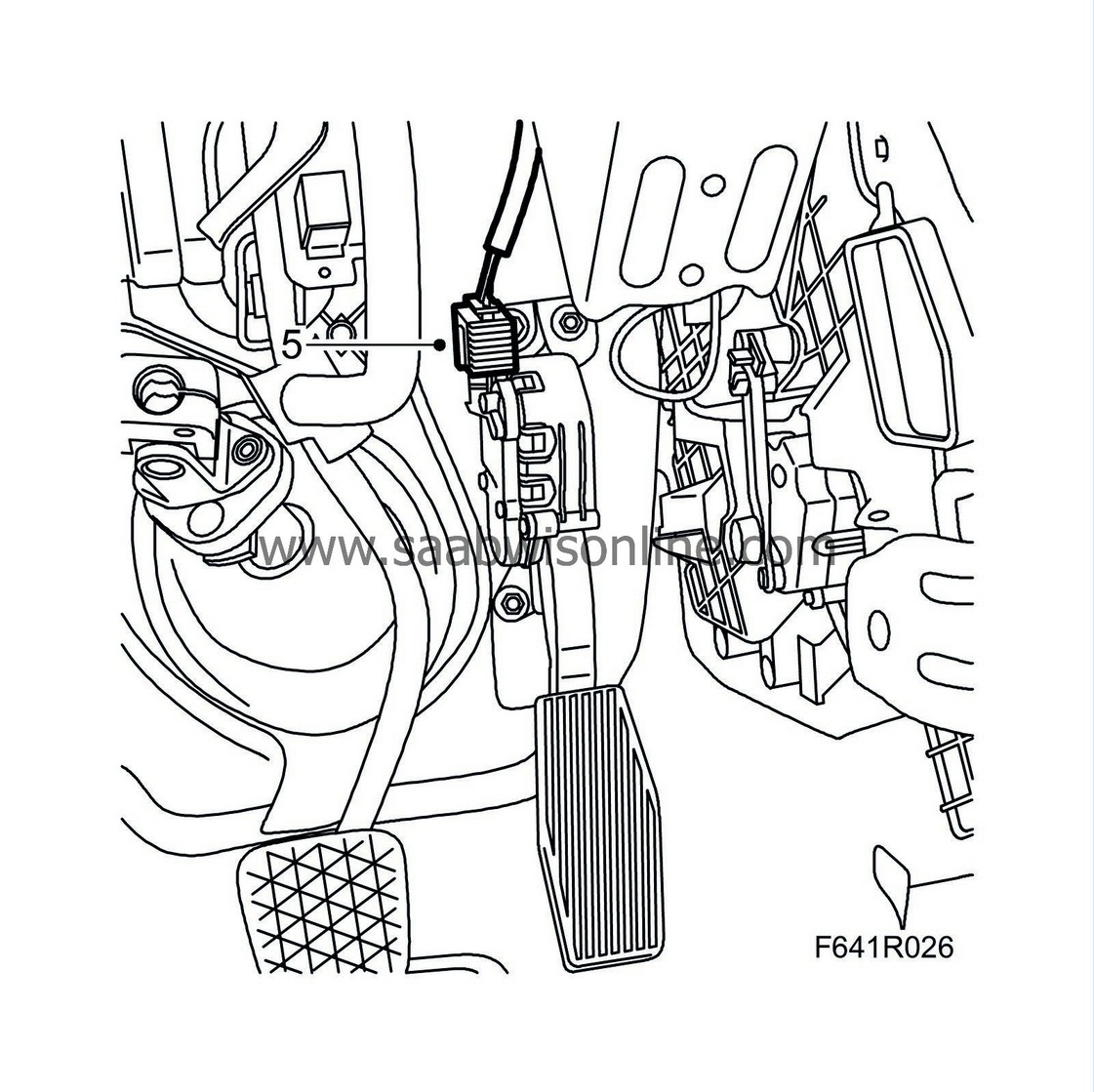
Unplug the accelerator pedal connector.
|
|
| 6. |
Cars with ACC:
Undo the wiring clips of the temperature sensor, instrument panel vent, driver's side.
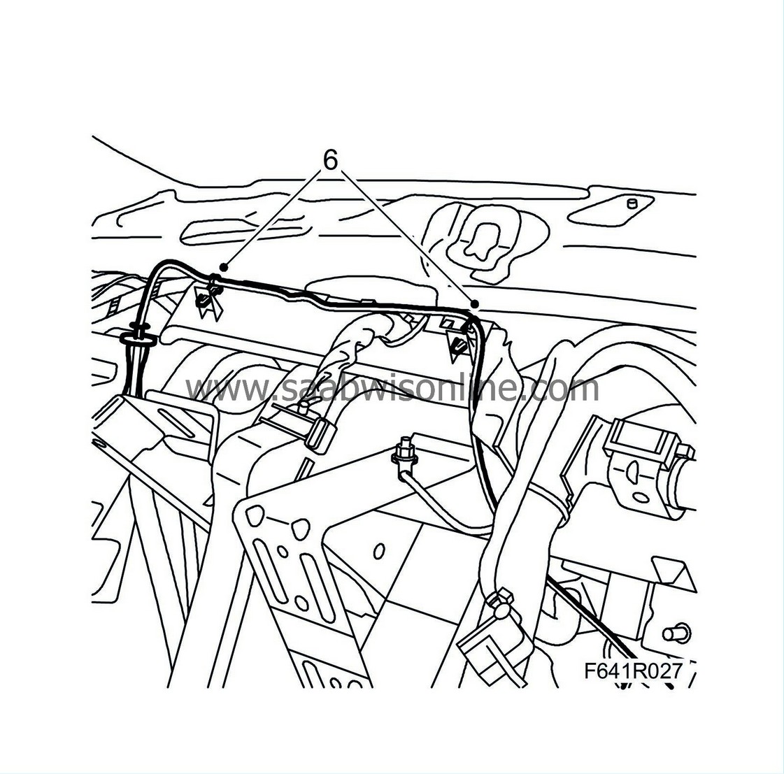
|
|
| 7. |
Remove the air ducts from the rear air vents.
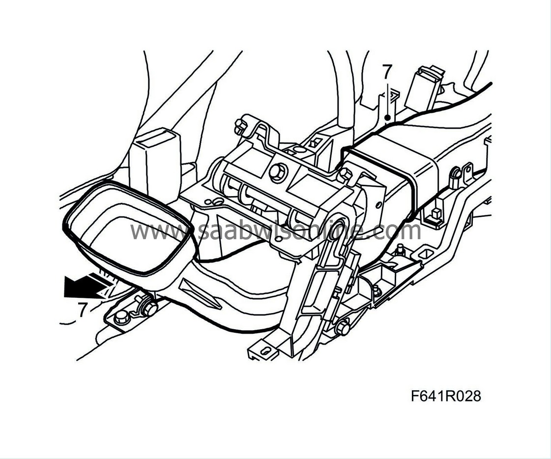
|
|
| 8. |
Cars with ACC:
Unplug the fan control unit connector.
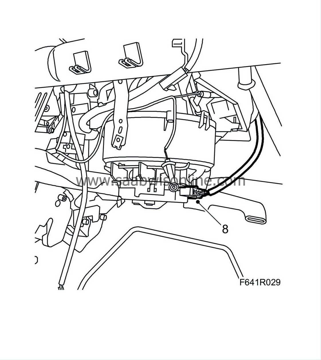
|
|
| 9. |
Cars with MCC:
Remove the connector from the control unit. Remove the air duct and undo the clip from the duct.
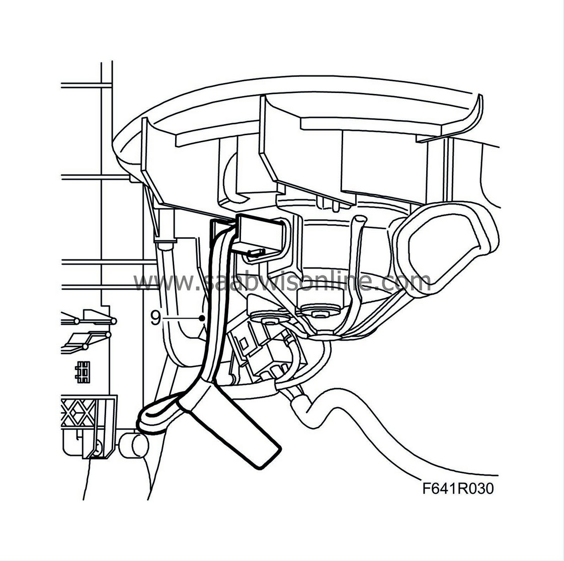
|
|
| 10. |
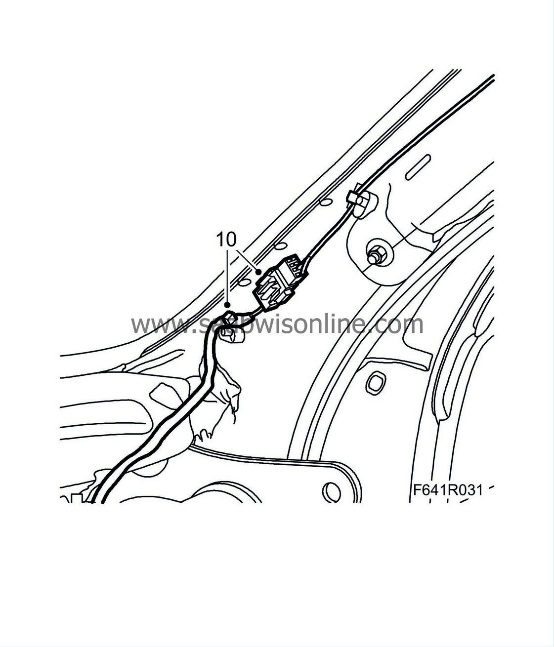
Undo the connector and its clips from the A-pillar.
|
|
| 11. |
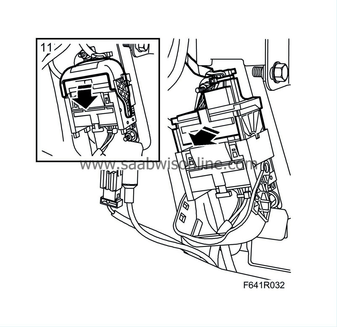
Undo the connector by the lower section of the A-pillars. Thread out the connector on the driver's side so that it comes on the inside of the cable from the bonnet opening handle.
|
|
| 12. |
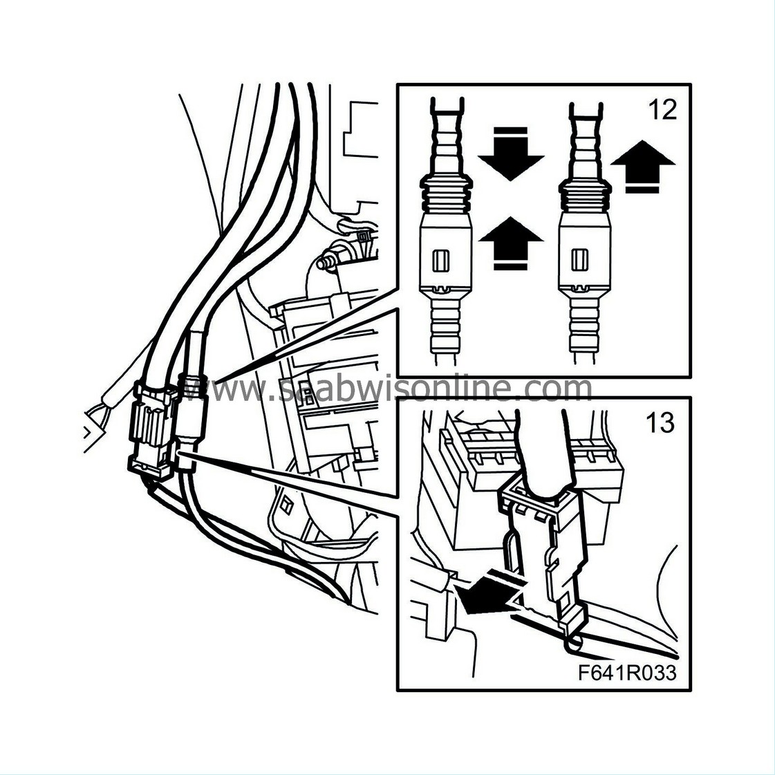
Remove the antenna cable on both sides. Unplug the connector by first pushing it together and then, whilst holding with a finger on the black part of the connector, pull it apart.
|
|
| 13. |
Remove the fibre optic cable on both sides. Fold up the locking tab and pull out the cable. Fibre optic cables must not be folded or pinched.
|
|||||||||
| 14. |
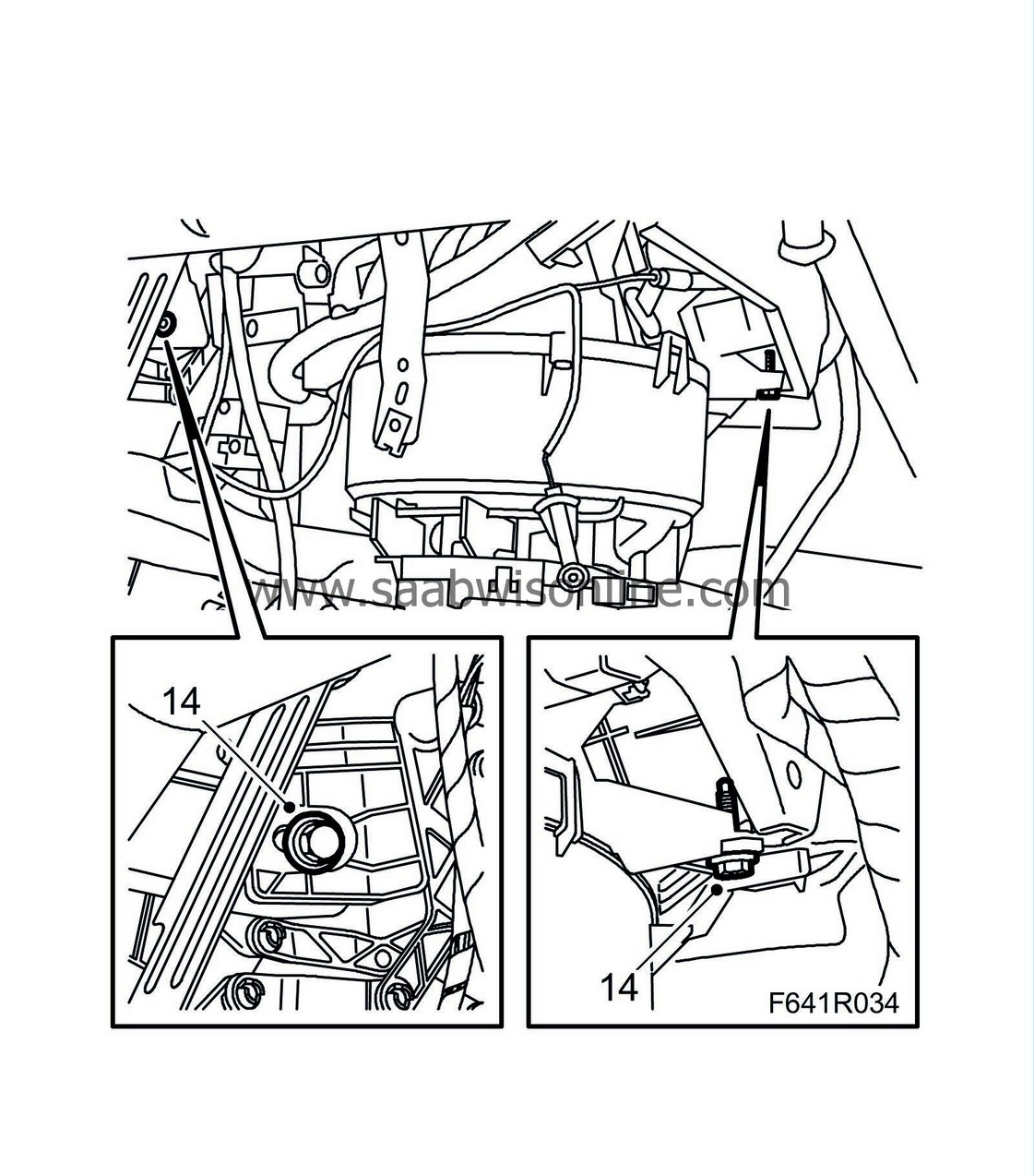
Remove the bolts on the right-hand side of the heating and ventilation unit that hold it in place.
|
|
| 15. |
Remove the heating and ventilation unit bolt from the centre mounting of the steering wheel member.
Undo the connector to the heating and ventilation unit. 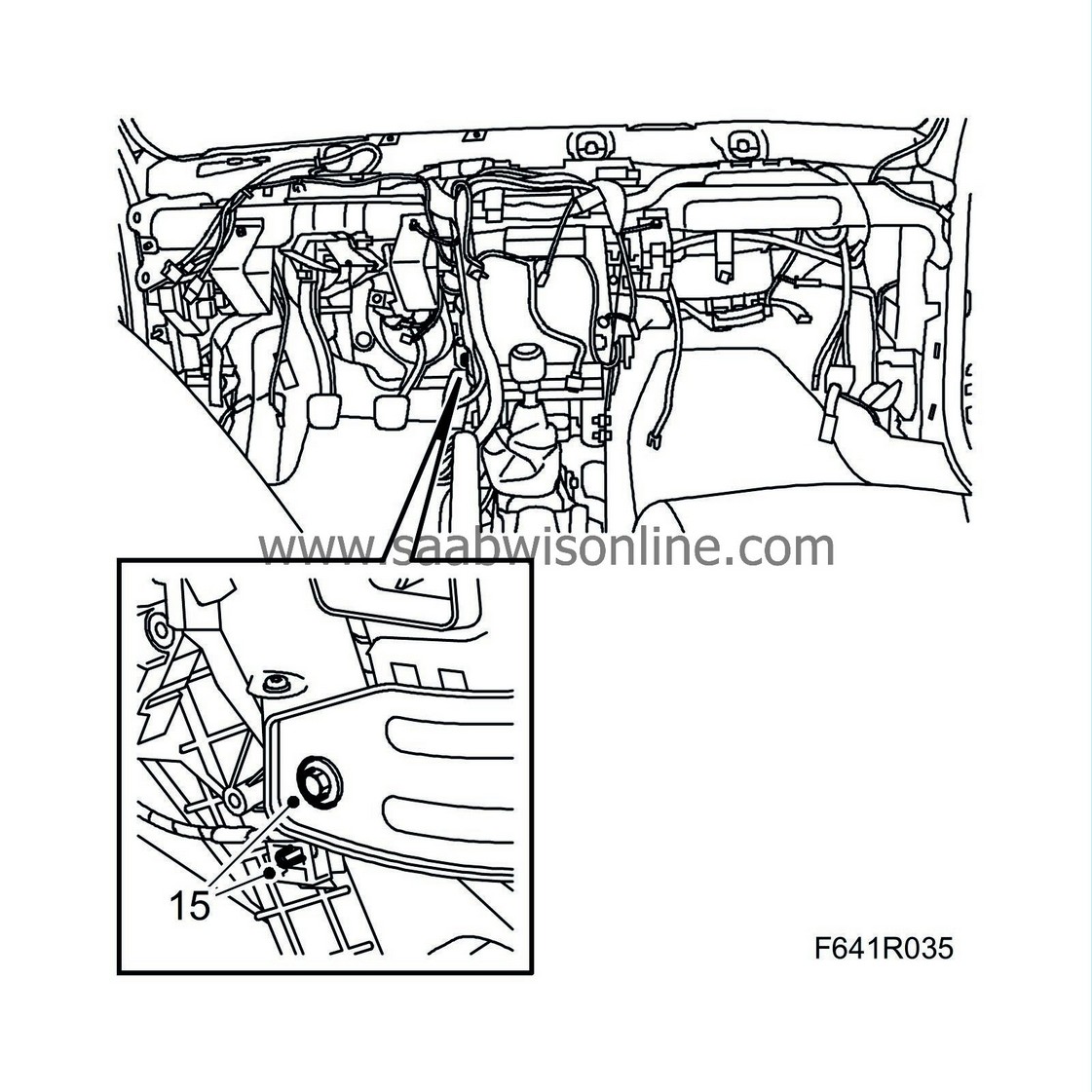
|
|
| 16. |
Remove the upper bolt holding the heating and ventilation unit in place.
Remove the wiring clip from the heating and ventilation unit 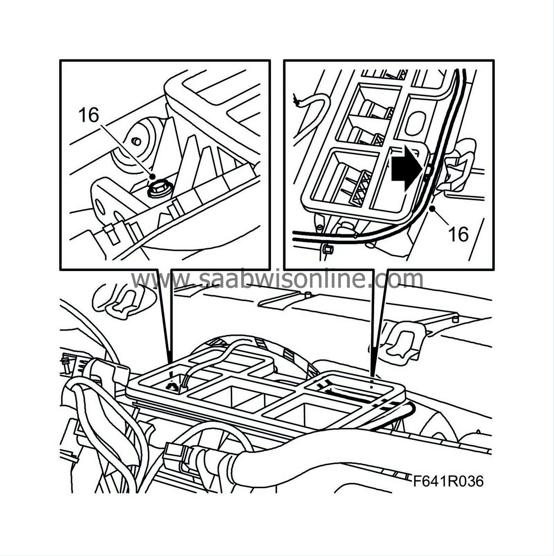
|
|
| 17. |
Remove the
front doors
.
|
|
| 18. |
Remove the rubber seals from the outside of the A-pillars.
|
|
| 20. |
Remove the
windscreen wiper assembly
.
|
|
| 21. |
Remove the steering wheel member nuts in the bulkhead partition space.
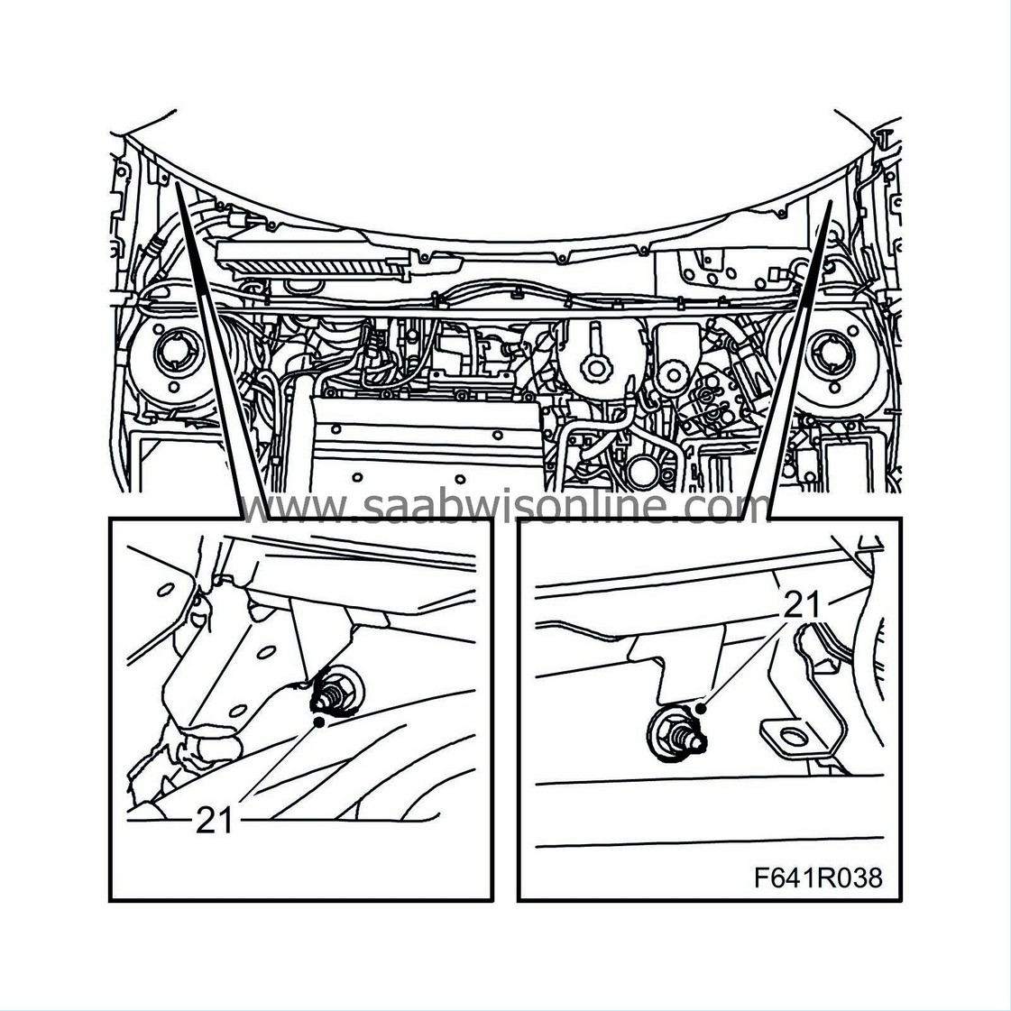
|
|
| 22. |
Remove the bolts from the steering wheel member at the lower section of A-pillars.
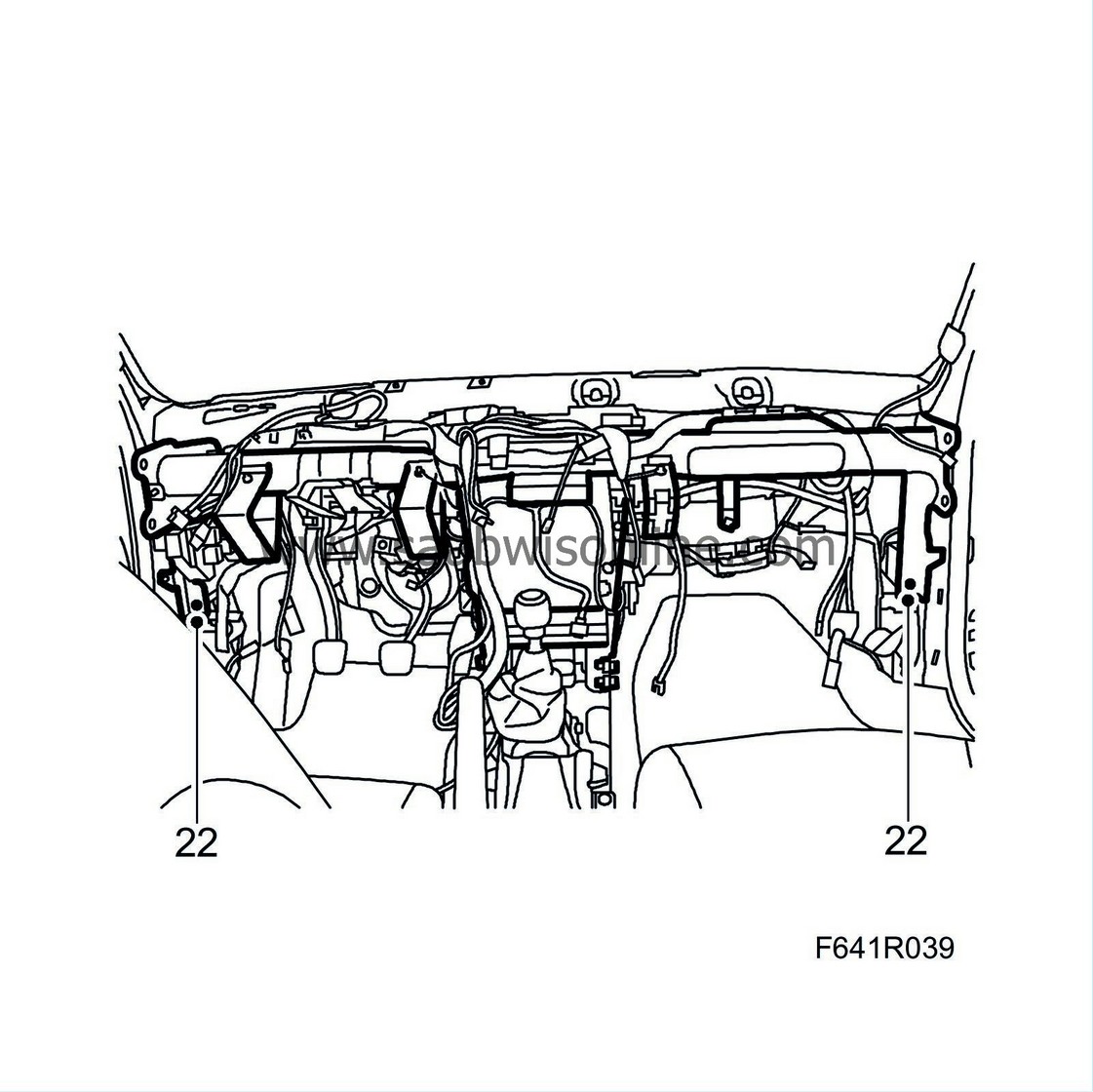
|
|
| 23. |
Remove the upper bolts from the centre mounting of the steering wheel member.
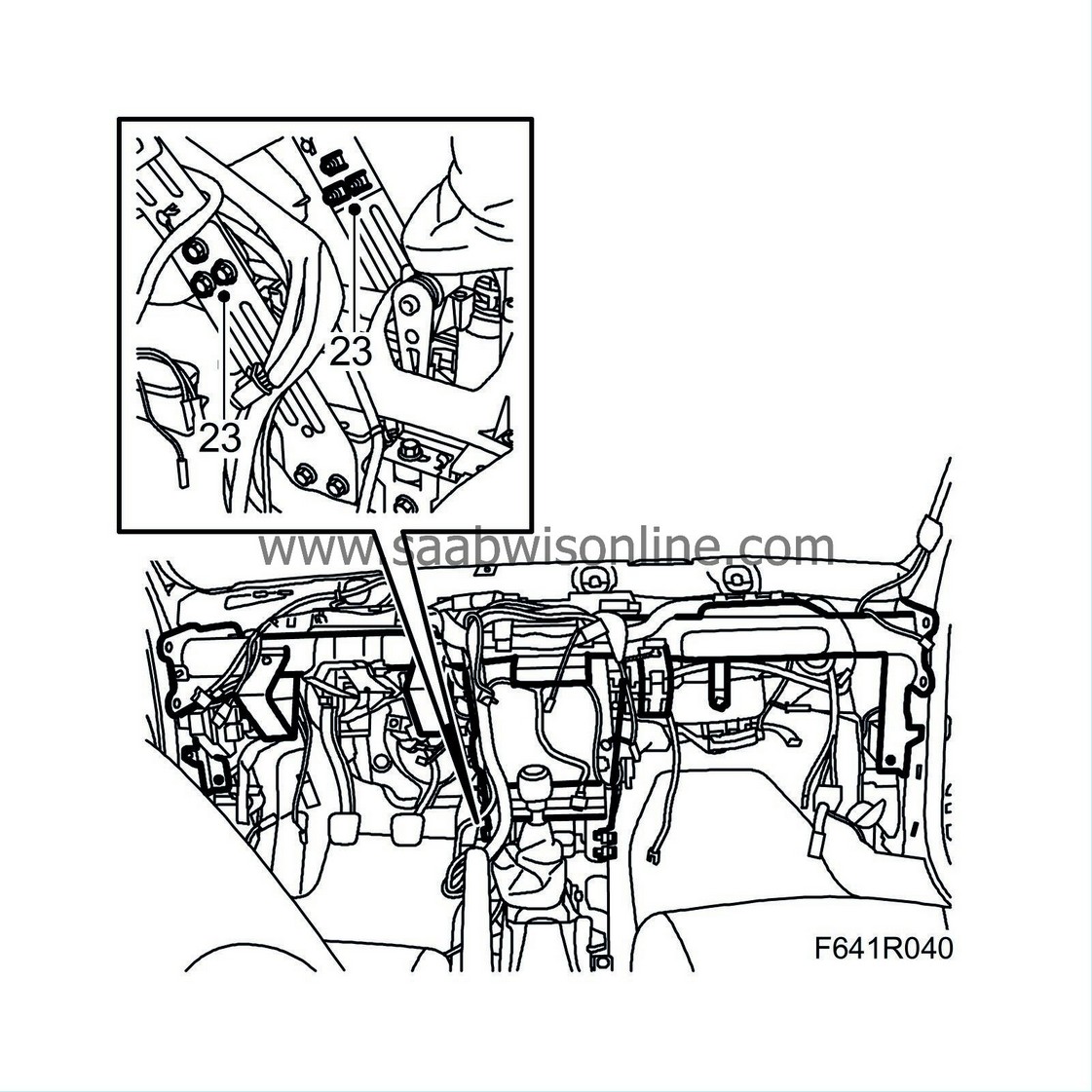
|
|
| 24. |
Undo the connector and the ground plinth of the ACM unit and the ignition switch.
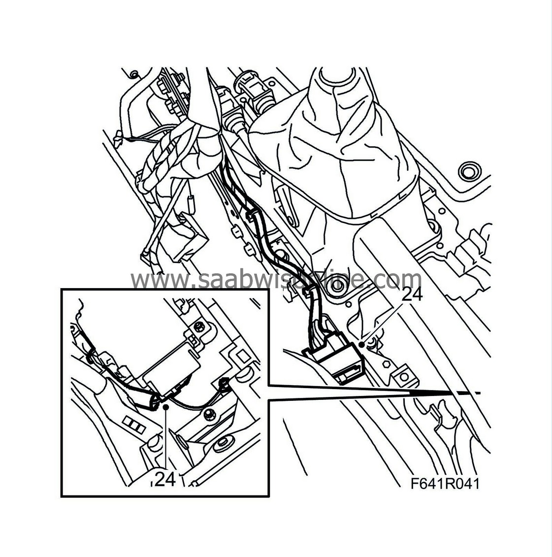
|
|
| 25. |
Undo the connector from the gyro. Undo the clips.
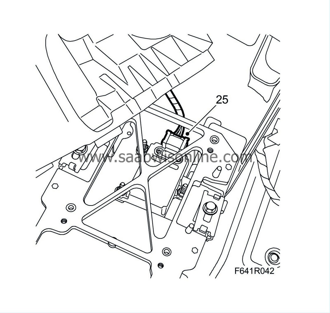
|
|
| 26. |
Remove the lower section of the centre mounting of the steering wheel member.
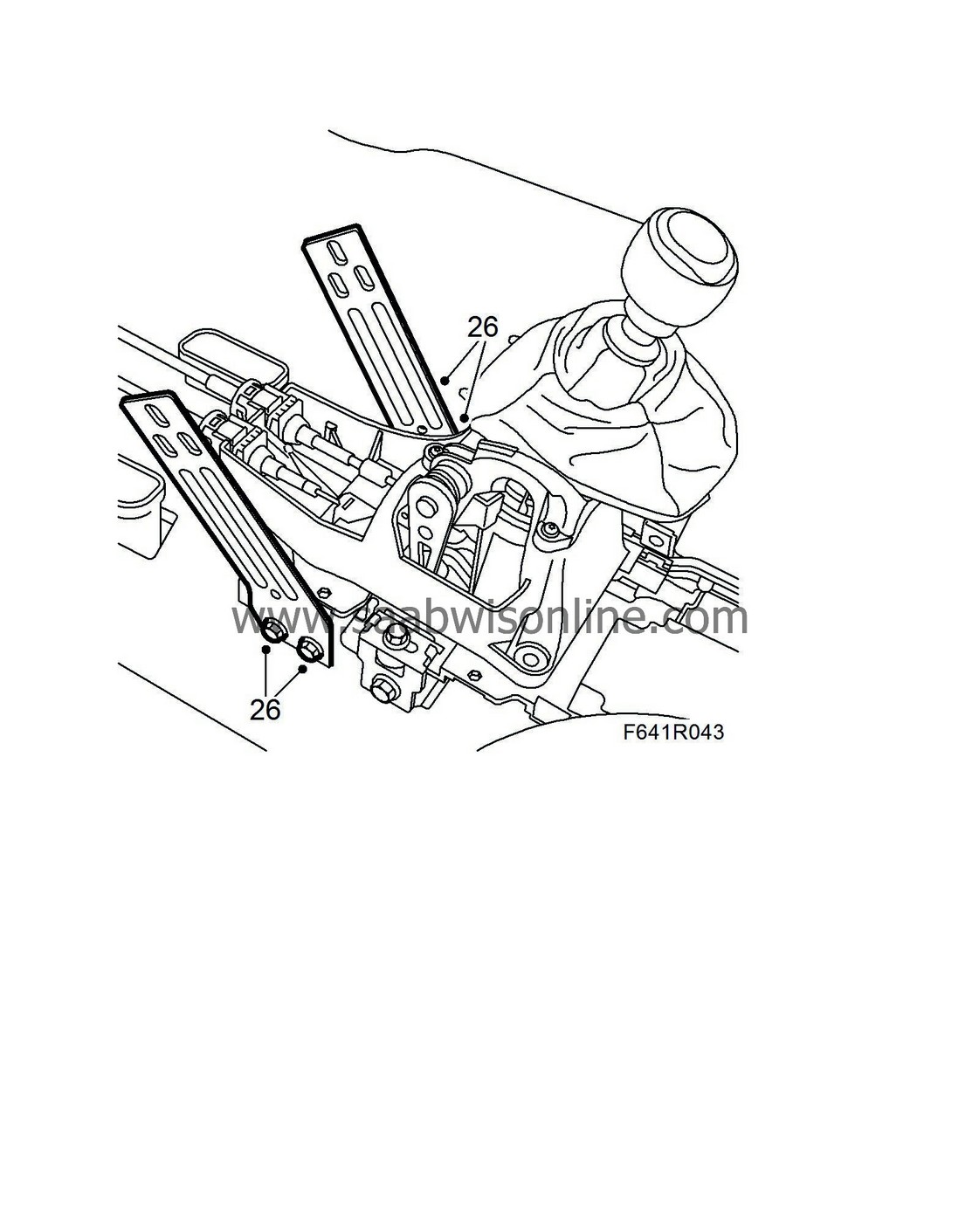
|
|
| 27. |
Carefully lift out the steering wheel member by manoeuvring it backwards whilst at the same time twisting it slightly upwards. Undo the cable clips and hang the wiring harness over the member.
|
|
| 28. |
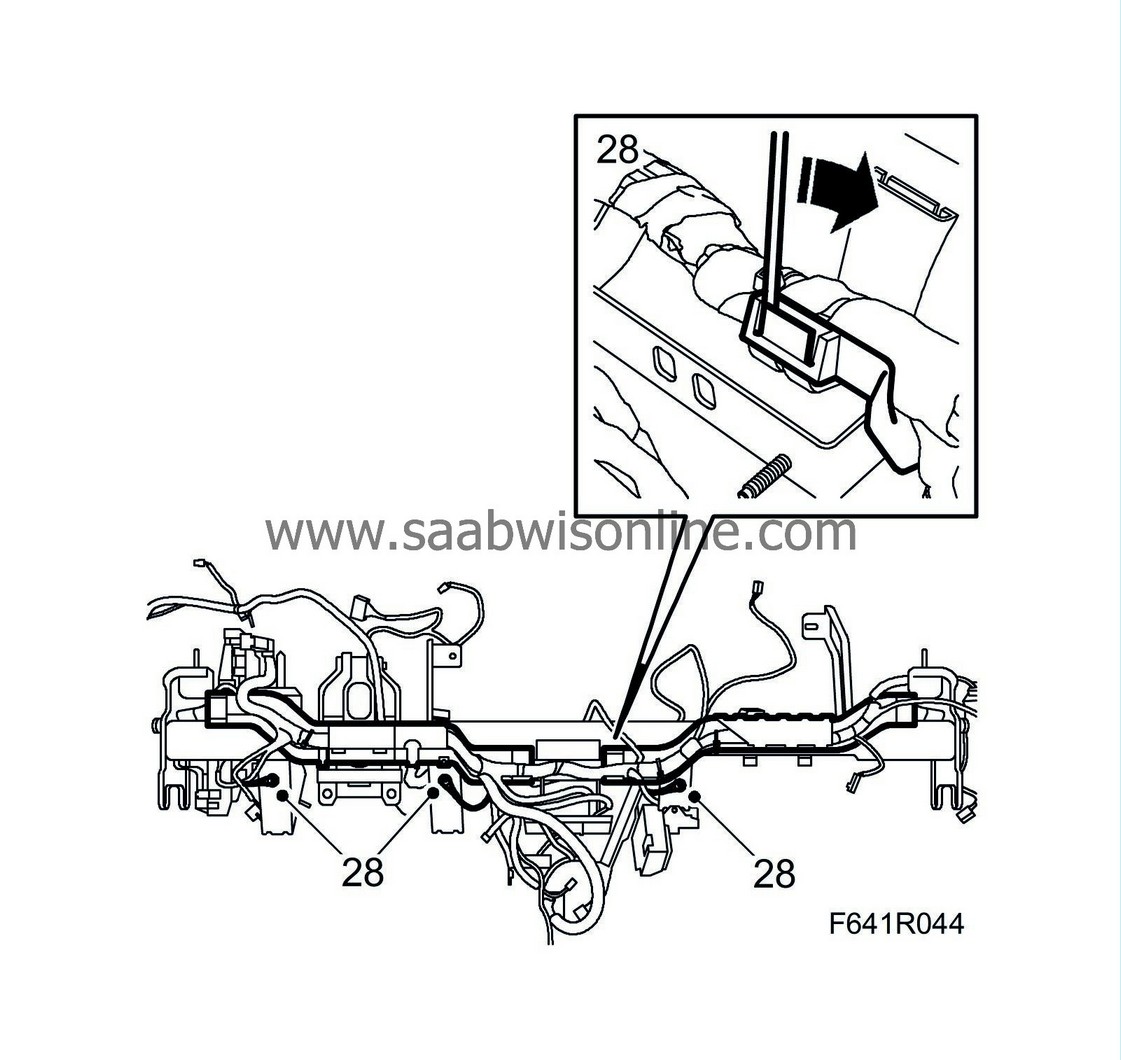
Remove the three ground connections and cable channels from the steering wheel member.
|
|
| 29. |
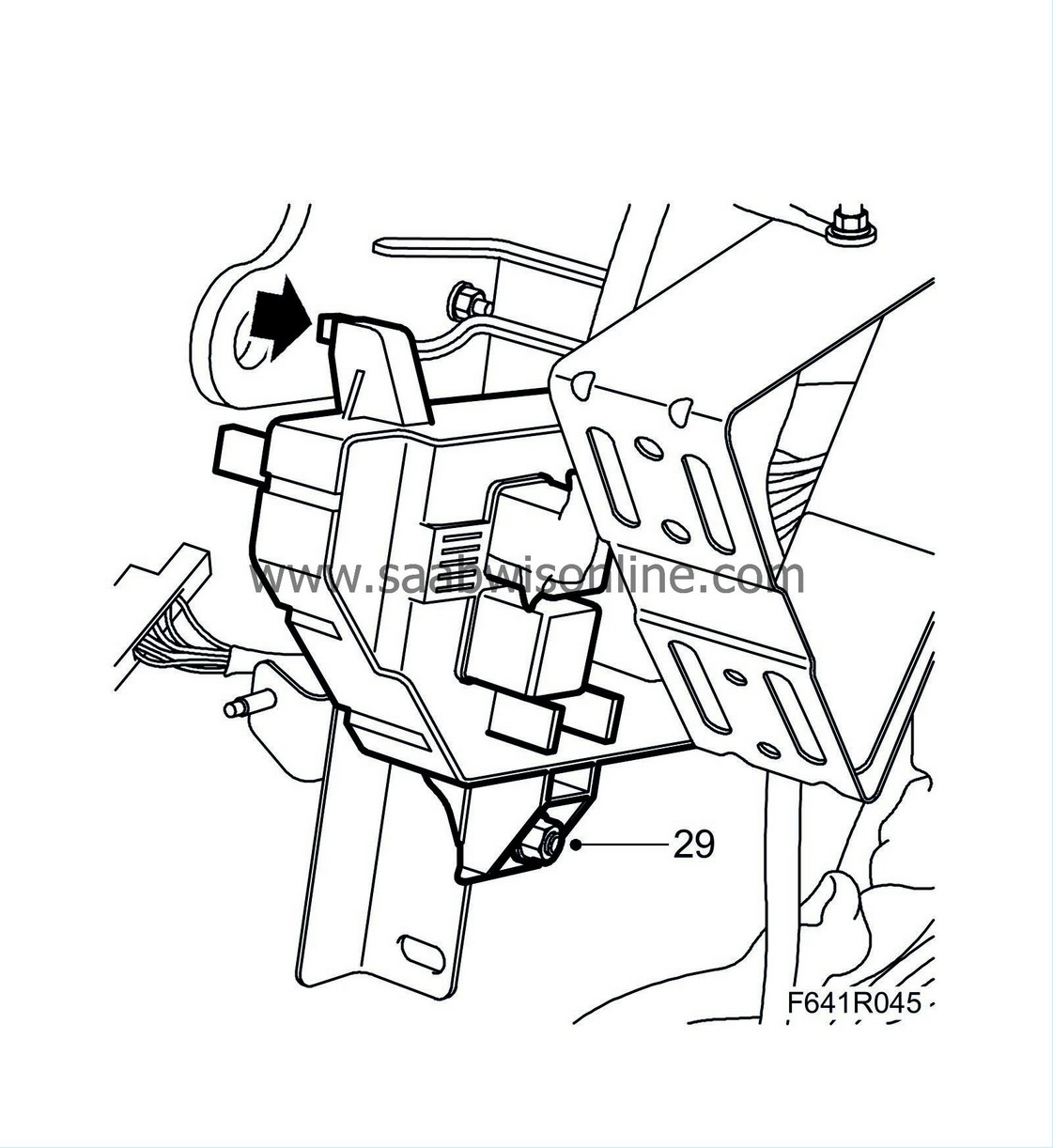
Remove the electrical centre and the BCM.
|
|
| 30. |
US/CA:
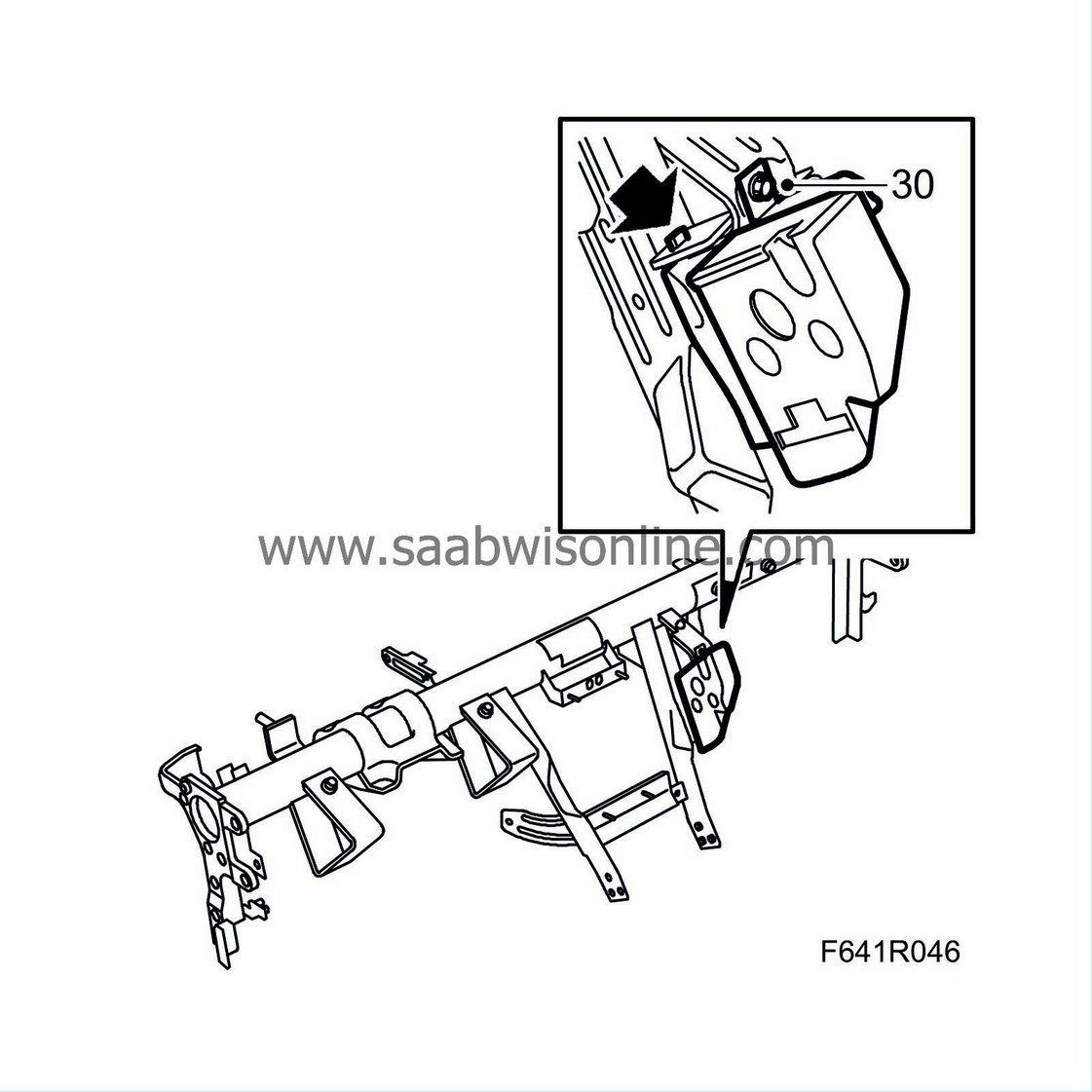
Remove the knee protector on the passenger side. If the knee protector is damaged it must be replaced.
|
|
| To fit |
| 1. |
US/CA:
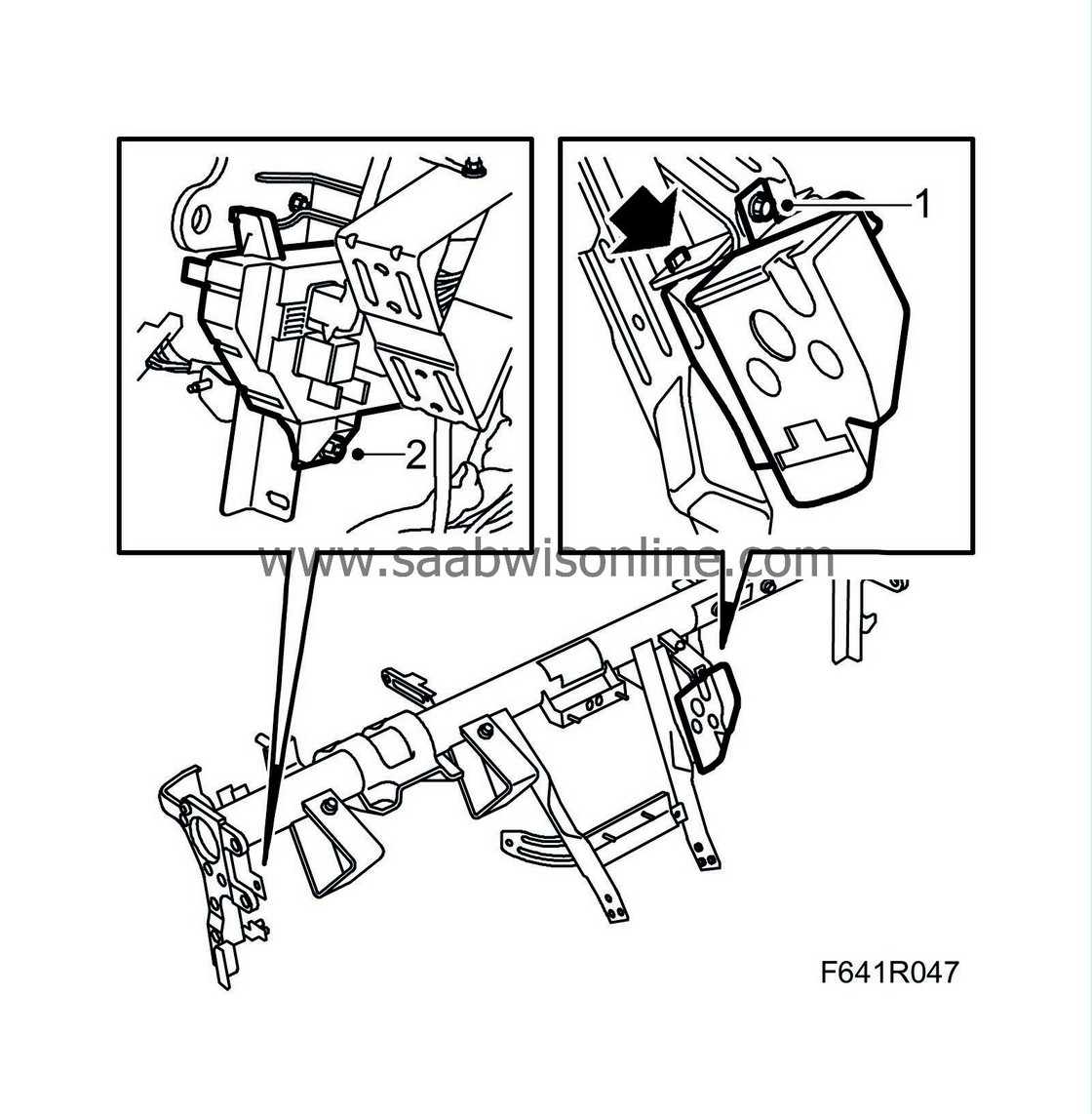
Fit the knee protector on the passenger side to the new steering wheel member.
|
|||||||
| 2. |
Fit new cable ties to the upper part of the pedal bracket.
|
|
| 3. |
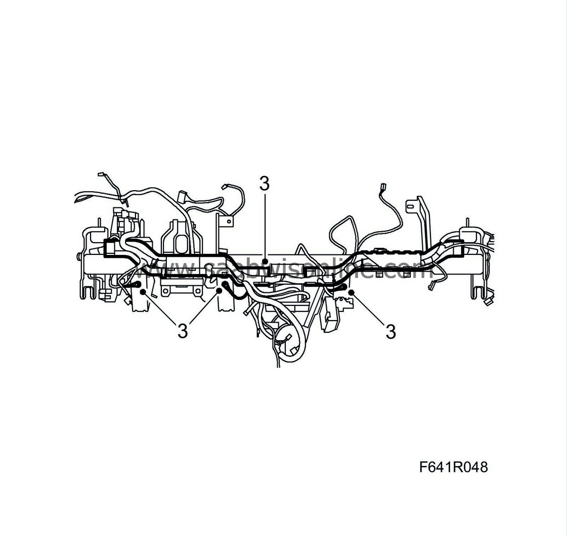
Fit the three ground connections and cable channels to the steering wheel member.
|
|
| 4. |
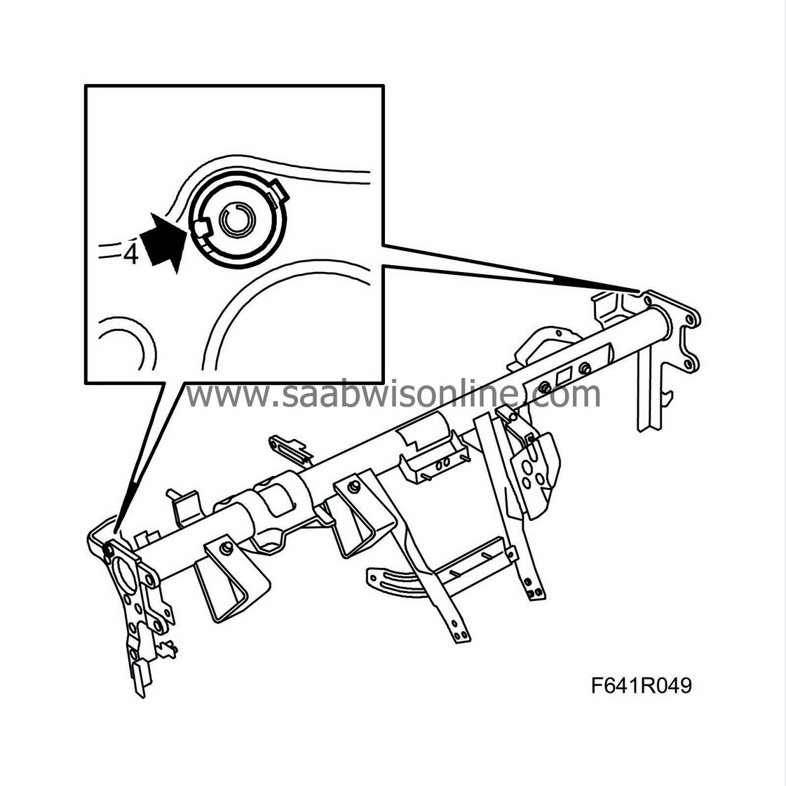
Ensure that the three adjusting nuts are completely screwed in and that the pad is between the plastic lugs.
|
|
| 5. |
Lift the steering wheel member into place. Ensure that no cables or connectors are caught up or pinched.
|
|
| 6. |
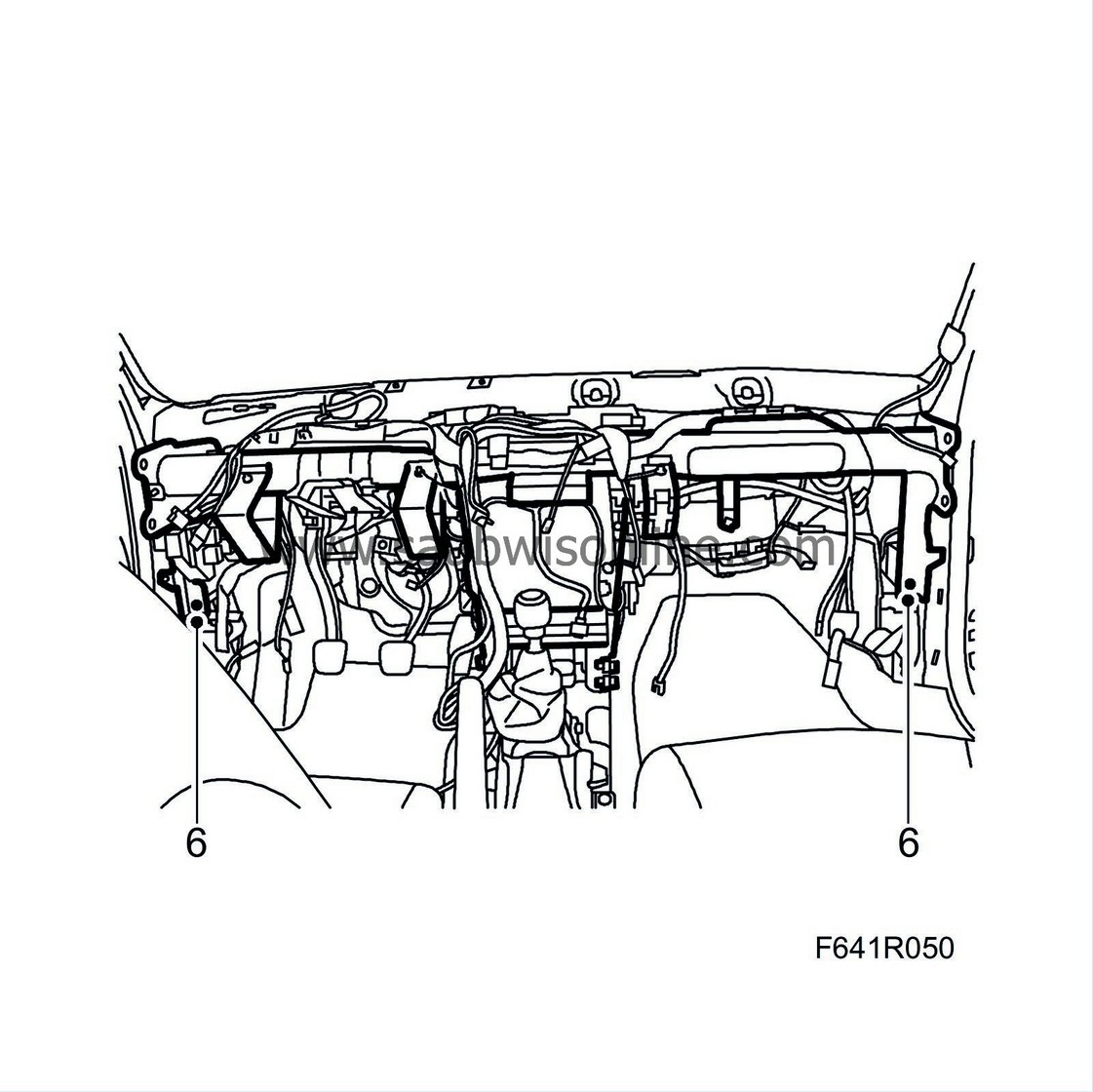
Insert the bolts in the steering wheel member mountings at the lower sections of the A-pillars as well as the bolts of the heating and ventilation unit.
|
|
| 7. |
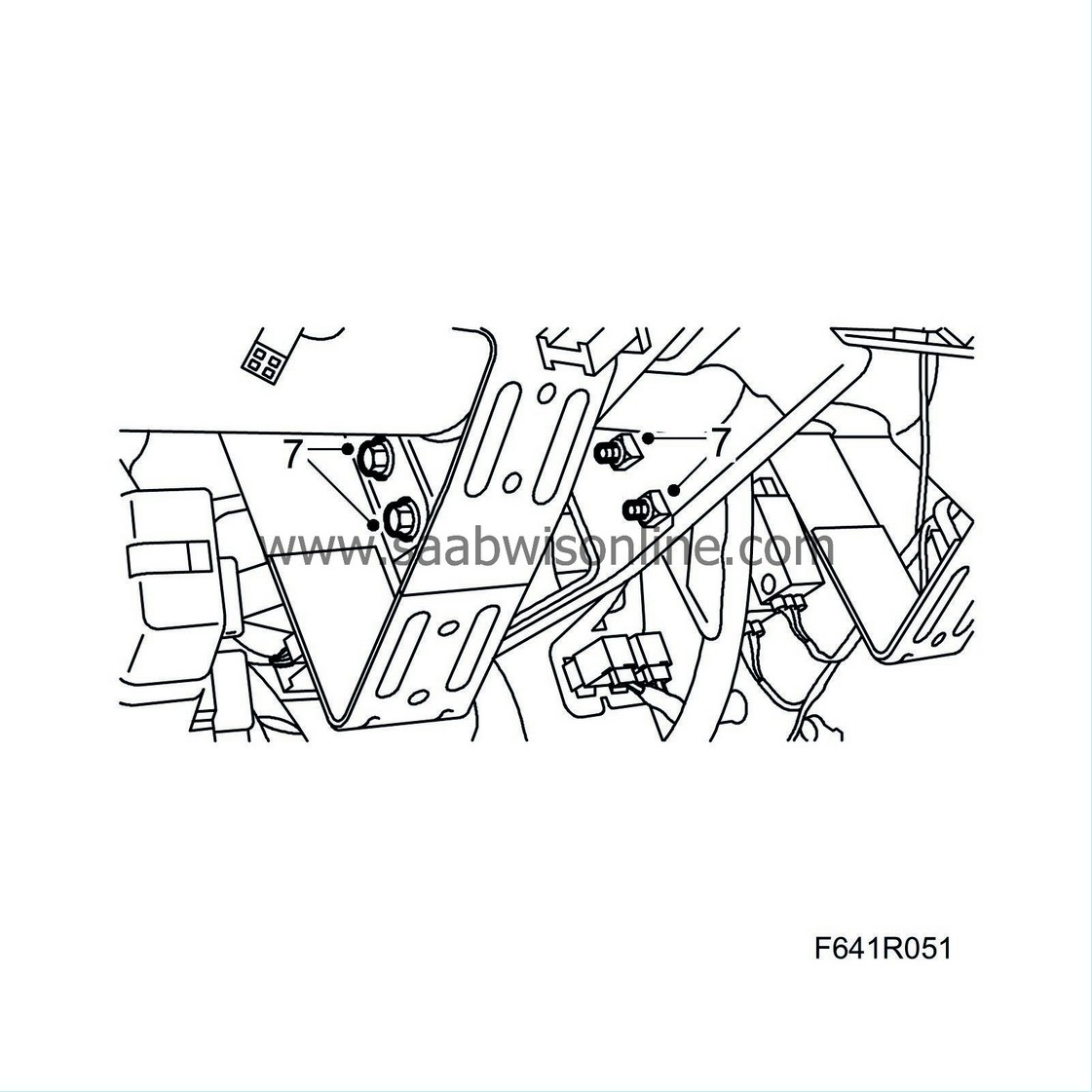
Loosely screw in place the pedal bracket bolts.
|
|
| 8. |
Loosely screw in place the bolts at the sides of the steering wheel member.
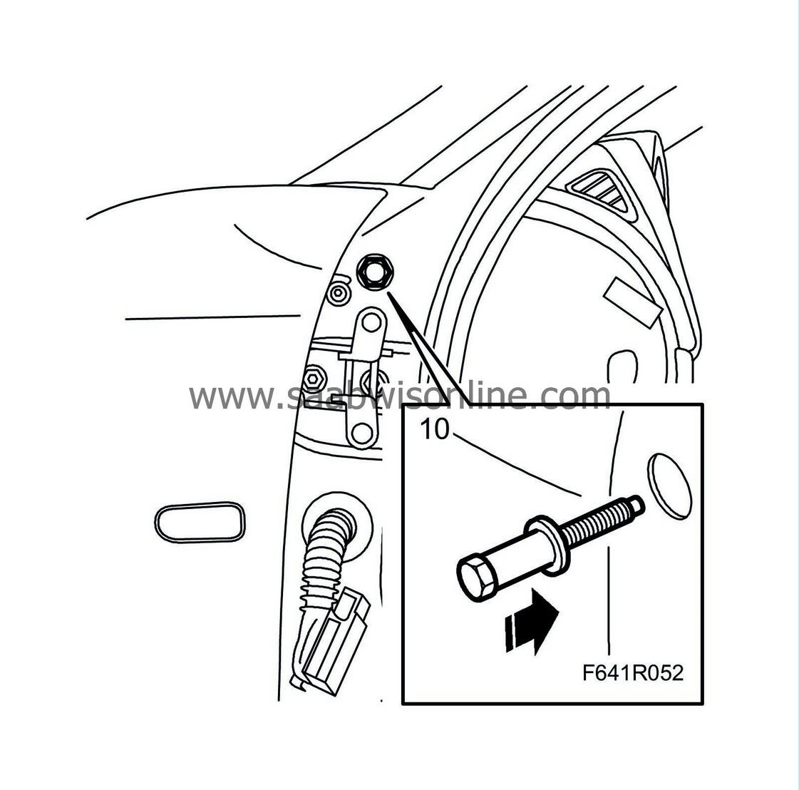
|
|||||||
| 9. |
Tighten the bolts of the steering wheel member mountings at the lower sections of the A-pillars.
Tightening torque 24 Nm (18 lbf ft) |
|
| 10. |
Fit the steering wheel member nuts in the bulkhead partition space.
Tightening torque 24 Nm (lbf ft) 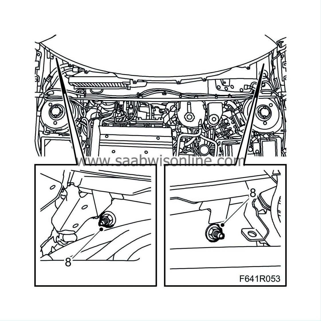
|
|
| 11. |
Fit the
windscreen wiper assembly
.
|
|
| 12. |
Tighten the bolts at the sides of the steering wheel member.
Tightening torque 24 Nm (18 lbf ft) Fit the rubber seals to the outside of the A-pillar. |
|
| 13. |
Fit the
front doors
.
|
|
| 14. |
Fit the wiring clip and the upper screw which holds the heating and ventilation unit in place.
Tightening torque 8 Nm (6 lbf ft) 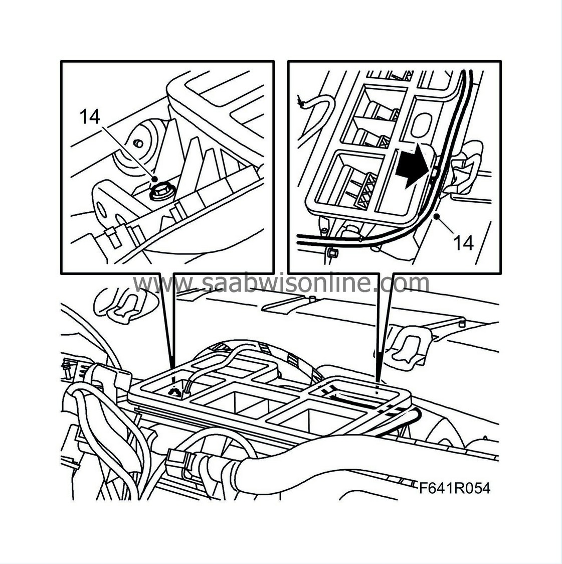
|
|
| 15. |
Assemble the heating and ventilation unit connector and the bolt which fastens the heating and ventilation unit to the centre mounting on the steering wheel member.
Tightening torque 8 Nm (6 lbf ft) 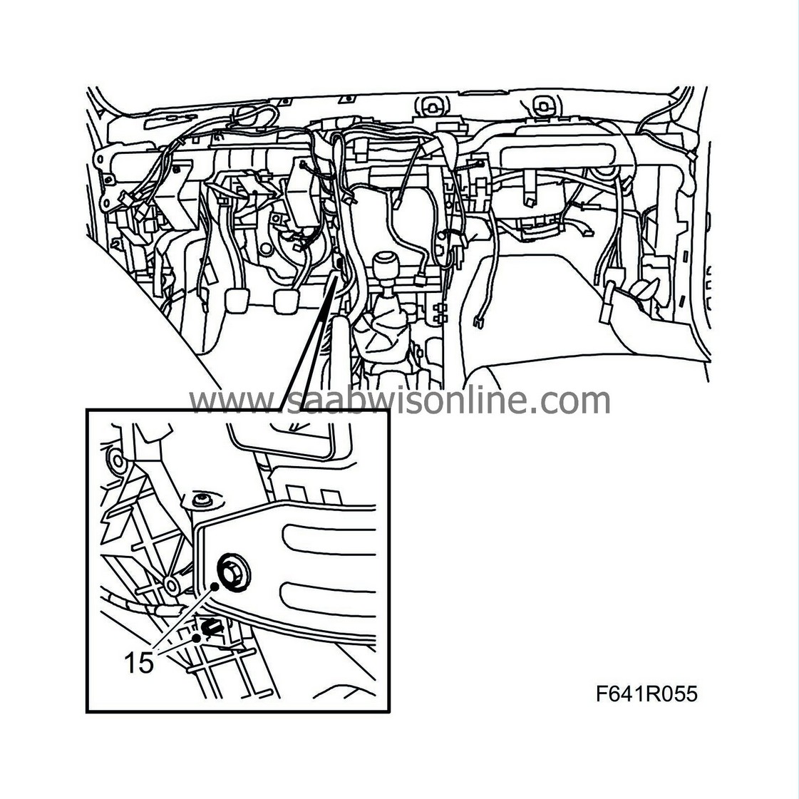
|
|
| 16. |
Tighten the bolts on the right-hand side of the heating and ventilation unit that hold it in place.
Tightening torque 8 Nm (6 lbf ft) 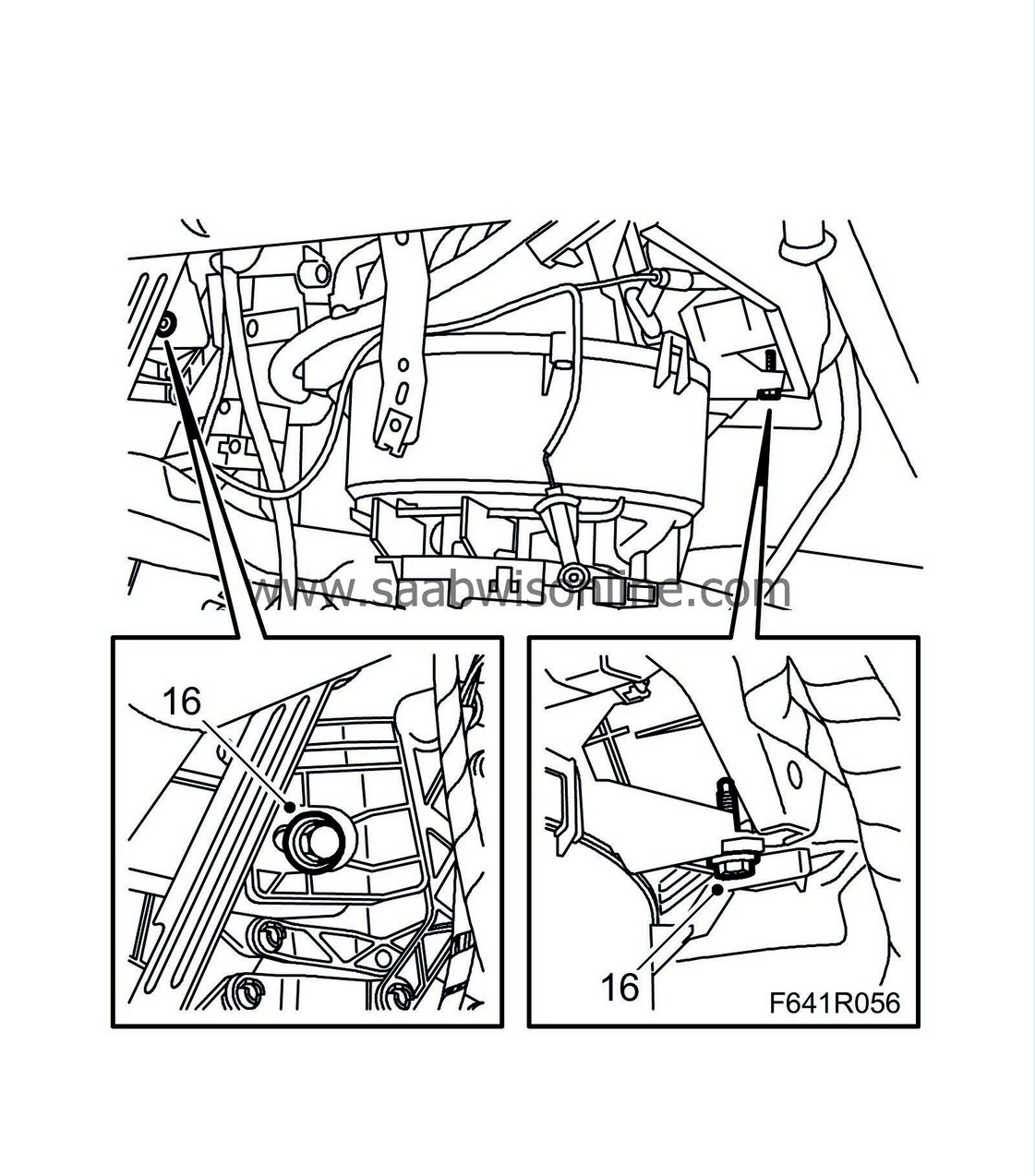
|
|
| 17. |
Plug in the ACM and ignition switch connectors.
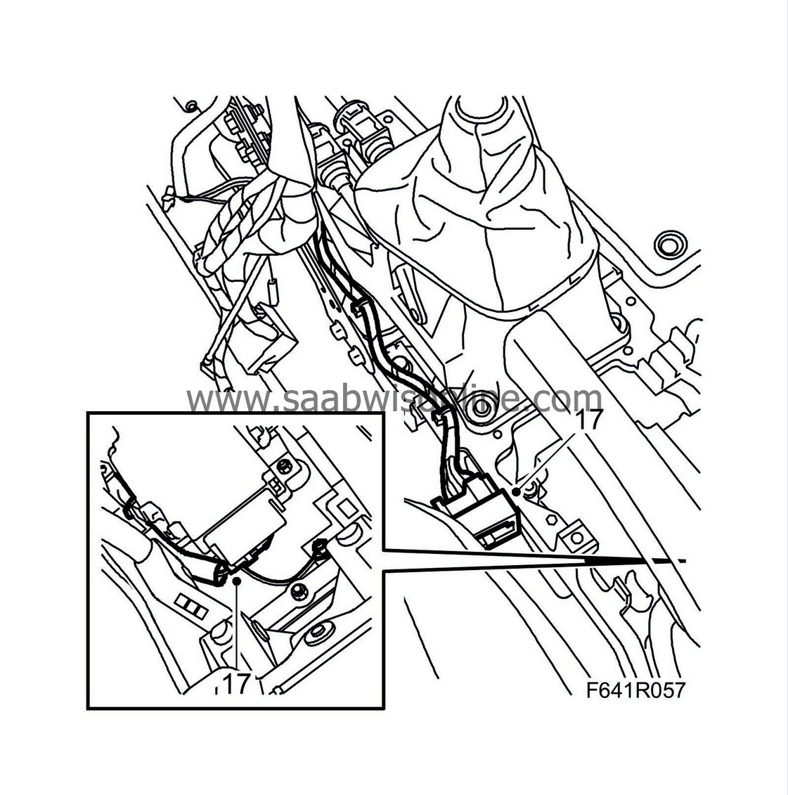
|
|
| 18. |
Plug in the gyro connector.
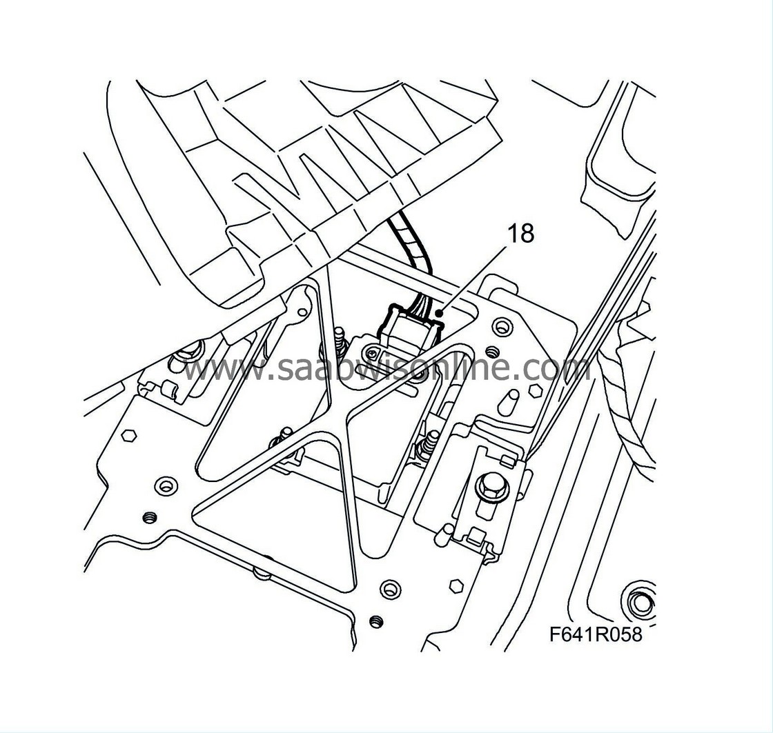
|
|
| 19. |
Fit the lower bolts to the mounting for the steering wheel member's centre mounting.
Tightening torque 33 Nm (24 lbf ft) 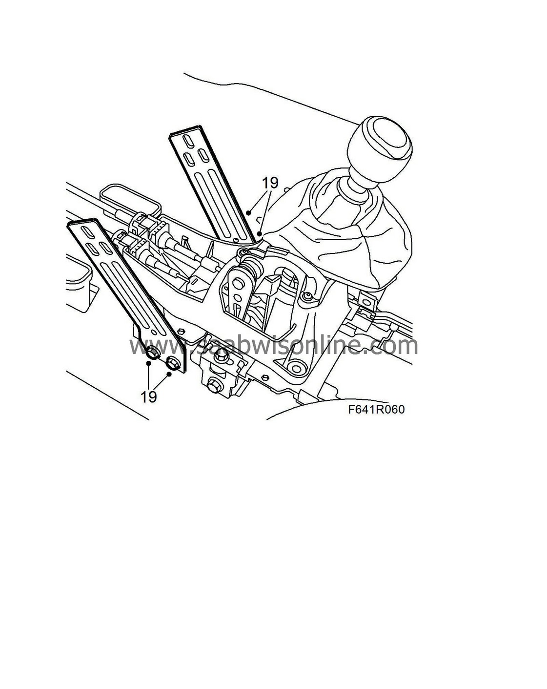
|
|
| 20. |
Fit the upper bolts of the steering wheel member's centre mounting.
Tightening torque 33 Nm (24 lbf ft) 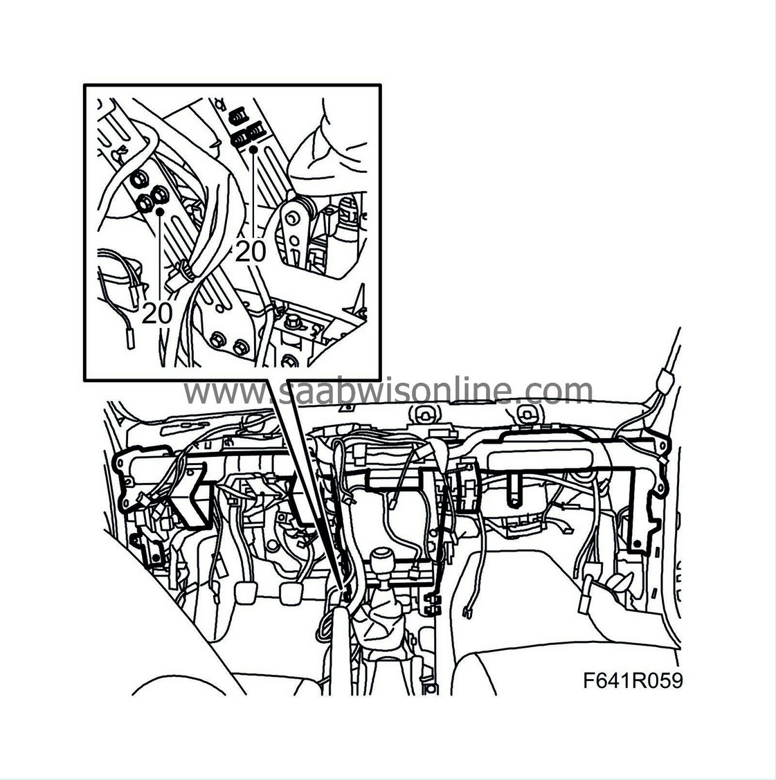
|
|
| 21. |
Fit the air ducts to the rear air vents and the bellows to the rear floor vents.
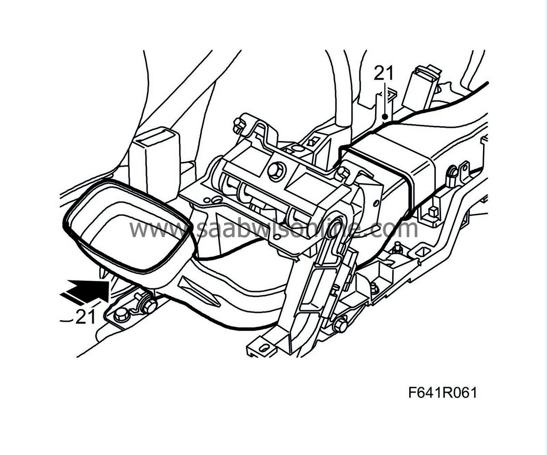
|
|
| 22. |
Connect the antenna cable.
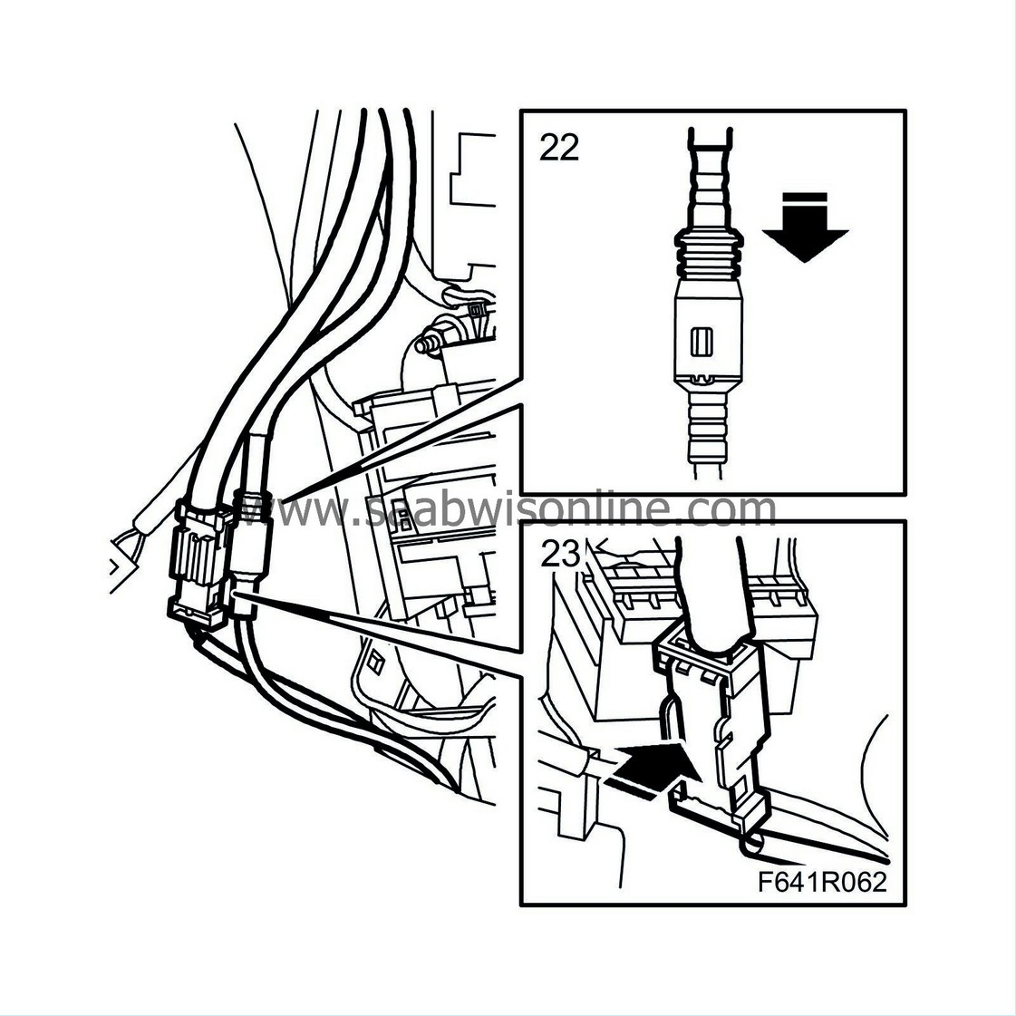
|
|
| 23. |
Connect together the fibre optic cables. Push the cable into the connector and fasten with the locking tab. Check that the ends are aligned. Fibre optic cables must not be folded or pinched.
|
|||||||||
| 24. |
Plug in the connectors by the bottom sections of the A-pillars and the large connector to the electrical centre.
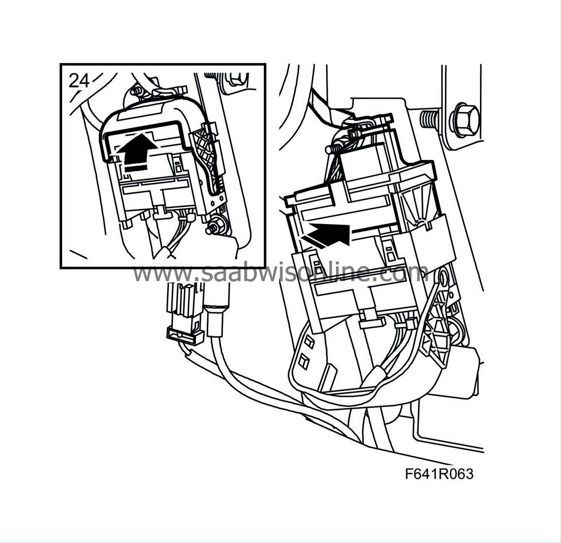
|
|
| 25. |
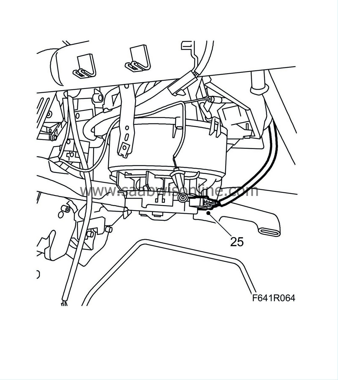
Cars with ACC:
Plug in the connector to the fan control unit.
|
|
| 26. |
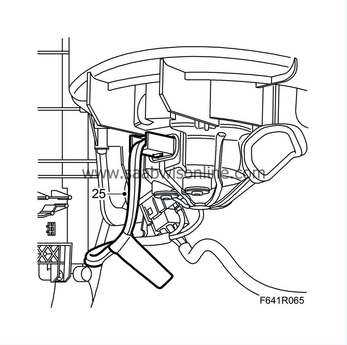
Cars with MCC:
Fit the connector to the control unit. Fit the air duct and the clip to the duct.
|
|
| 27. |
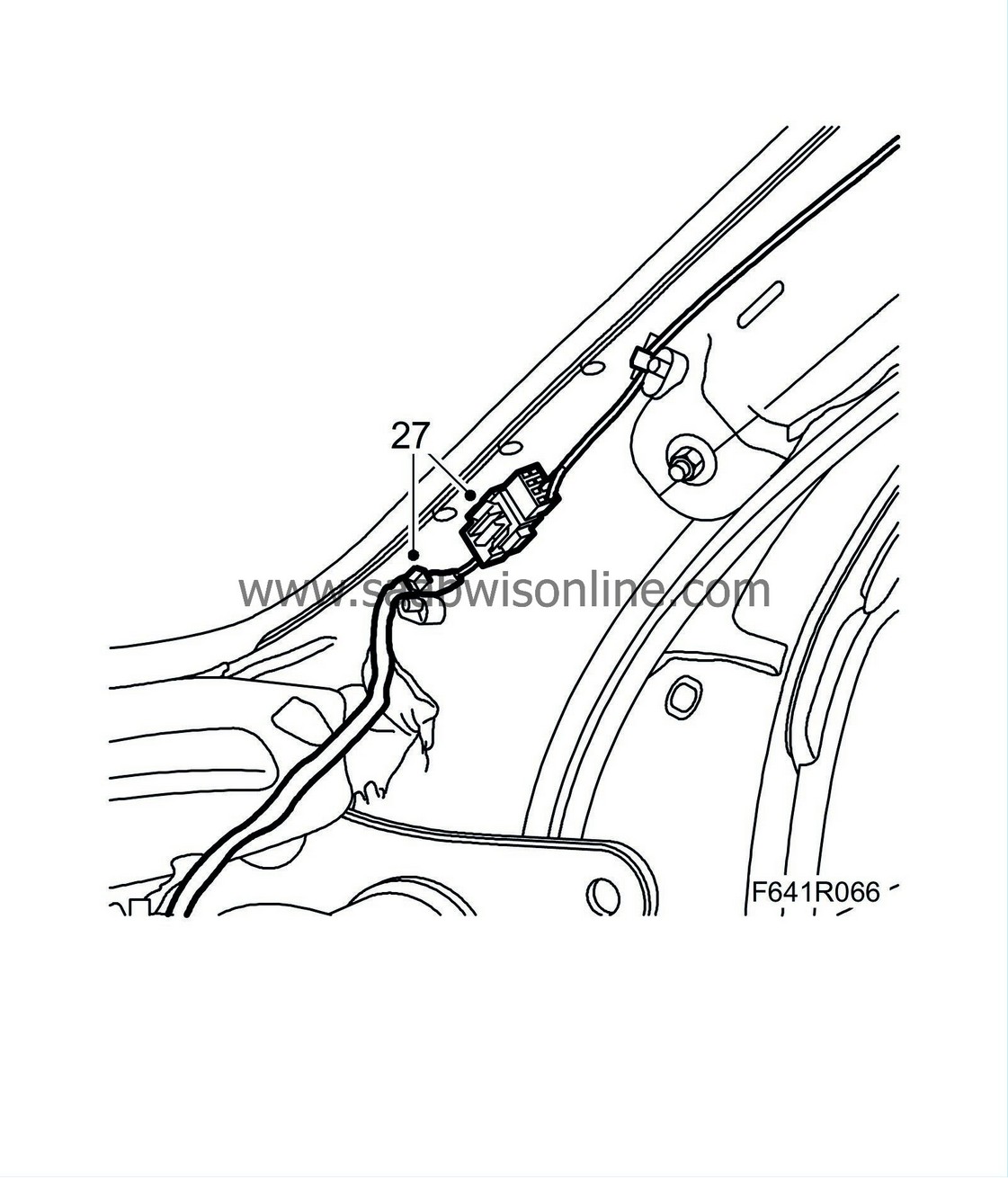
Plug in the connector on the A-pillar and fit the clip.
|
|
| 28. |
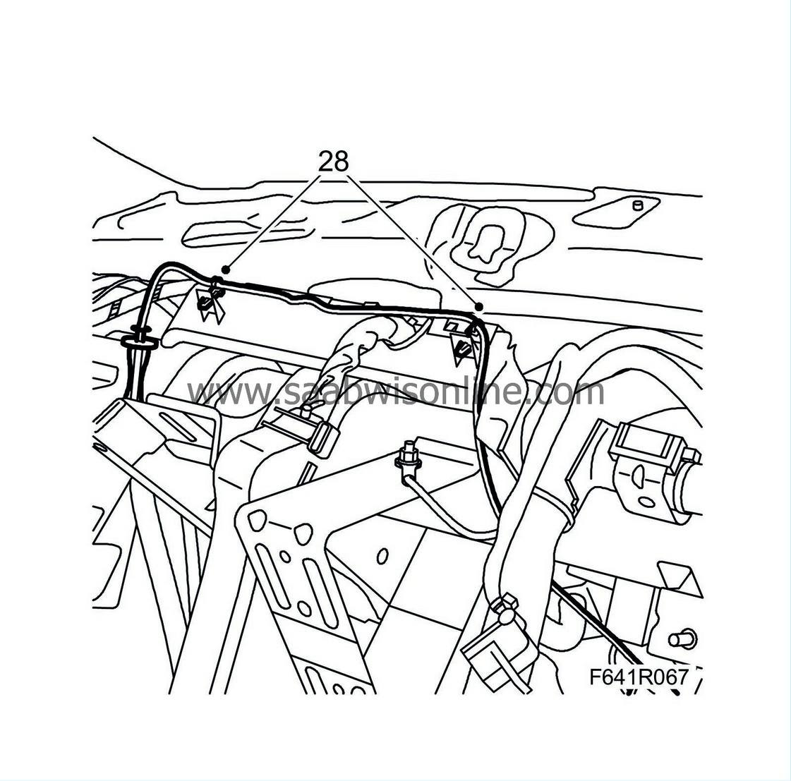
Cars with ACC:
Fit the temperature sensor wiring clips, instrument panel vent, driver's side.
|
|
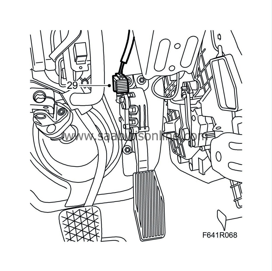
| 29. |
Plug in the accelerator pedal connector.
|
|
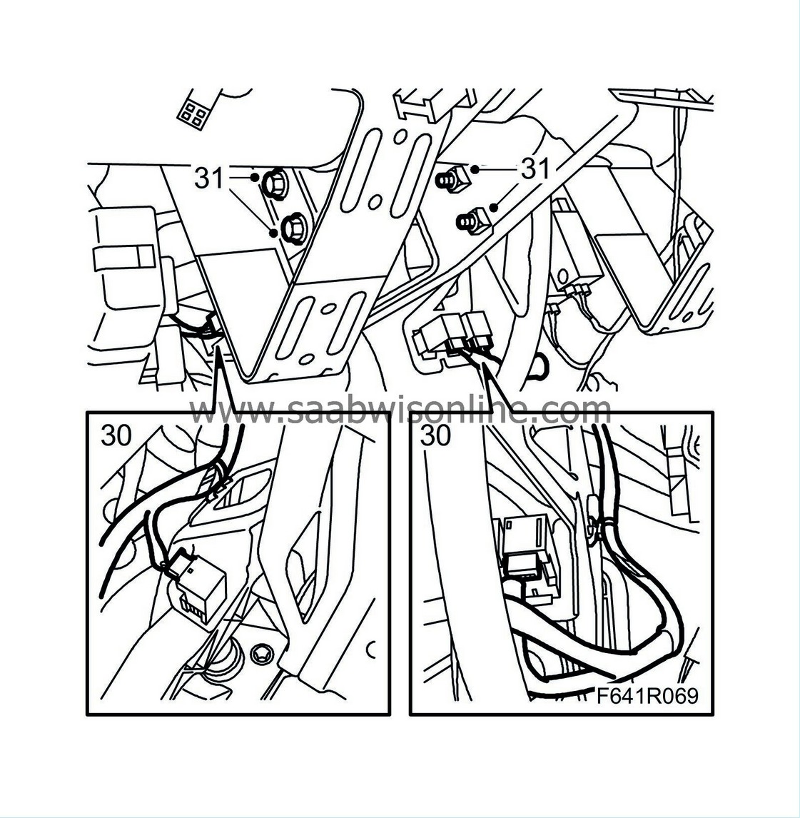
| 30. |
Plug in the pedal connectors and fit the clips to the cables.
|
|
| 31. |
Tighten the bolts holding the pedal bracket.
Tightening torque 24 Nm (18 lbf ft) |
|
| 32. |
Adjust the pedal switches by pressing in the pedal as far as possible. Hold the front of the pedal switch and pull the plastic pin until it reaches its stop. Then release the pedal all the way back. A click should be heard.
Adjust the clutch pedal switch and the two pedal switches of the brake. |
|
| 33. |
Fit
steering column assembly
.
|
|
| 34. |
Fit the
instrument panel
.
|
|

 Warning
