A-pillar assembly, CV
| A-pillar assembly, CV |
Certain welded joints on the car may be MIG brazed with bronze as the filling material. A MIG brazed seam may be recognized from the gold colour of the joint. A MIG brazing must always be replaced by a new MIG brazing.
|
|||||||
| 1. |
Position the car in an aligning bench and cross-measure if necessary.
|
|
| 2. |
Remove the
Front wing
,
Bonnet
and
Front door
.
|
|
| 3. |
Drill out the spot welds as illustrated. Drill out the upper welds only so that the nut piece follows.

|
|
| 4. |
Grind away the seam and continuous welds according to the illustration. Note that the seam welds are MIG brazed.
|
|
| 5. |
Knock loose the reinforcement.
|
|
| 6. |
Cut the windscreen frame outer panel 250 mm from the outer edge of the A-pillar. Do not cut the underlying panel.

|
|
| 7. |
Grind the seam welds holding the A-pillar outer panel.
|
|
| 8. |
Drill out the spot welds holding the A-pillar outer panel.
|
|
| 9. |
Tap the outer panel of the A-pillar loose.
|
|
| 10. |
Cut the sill as illustrated. Cut carefully to avoid damaging the inner sill. Cutting should be done near the square hole.

|
|
| 11. |
Drill out and grind any spot welds as illustrated.
|
|
| 12. |
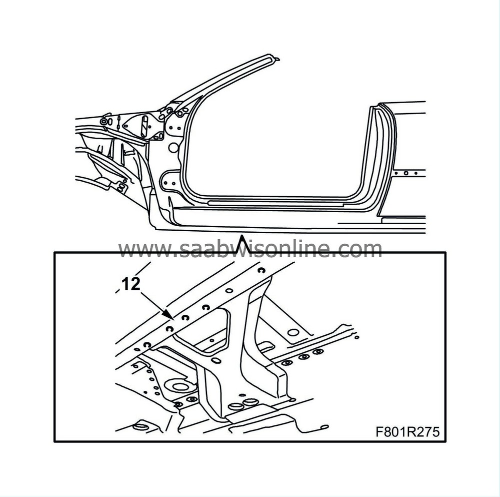
Drill out the welds in the front floor reinforcement.
|
|
| 13. |
First, tap the upper section of the outer sill loose and bend out the upper part. Tap the lower section of the sill loose and the reinforcement bulkhead (glued). You can stop here or continue to step 66 depending on the amount of damage.
|
|
| 14. |
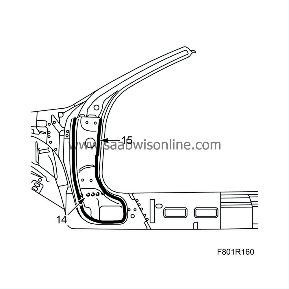
Drill out the spot welds holding the hinge reinforcement to the underlying bulkhead.
|
|
| 15. |
Cut around the entire hinge reinforcement.
|
|
| 16. |
Grind away remaining pieces of the hinge reinforcement. You can stop here or continue to step 62 depending on the amount of damage.
|
|
| 17. |
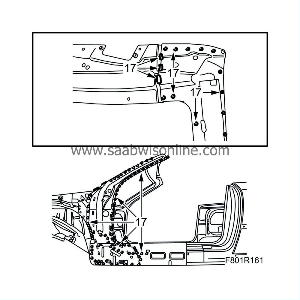
Grind the seam welds to the centre section of the A-pillar on the windscreen frame. Drill out the spot welds.
|
|
| 18. |
Tap the centre A-pillar loose.
|
|
| 19. |
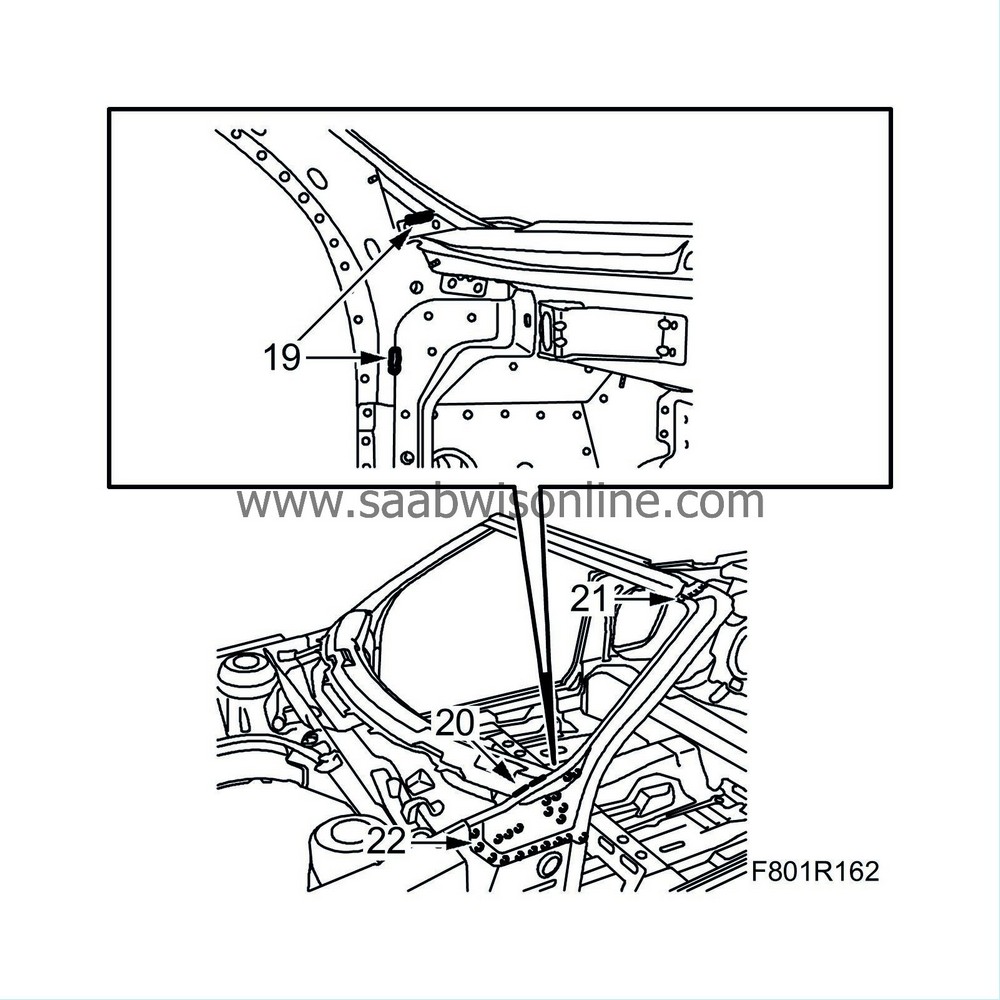
Grind the inner seam welds to the upper A-pillar inner panel.
|
|
| 20. |
Grind the seam welds to the upper A-pillar inner panel on the windscreen member.
|
|
| 21. |
Drill out the spot welds to the upper A-pillar inner panel on the windscreen frame. Provide support for the frame at the same time.
|
|
| 22. |
Drill out the lower spot welds to the upper A-pillar inner panel.
|
|
| 23. |
Tap the upper A-pillar inner panel loose and align any damaged sheet metal or panels.
|
|
| 24. |
Cut as illustrated. Do not cut the underlying panel.

|
|
| 25. |
Drill out the spot welds to the centre sill section.
|
|
| 26. |
Tap the centre sill section loose.
|
|
| 27. |
Mark and cut the inner sill as indicated by the marks. Do not cut the underlying panel.

|
|
| 28. |
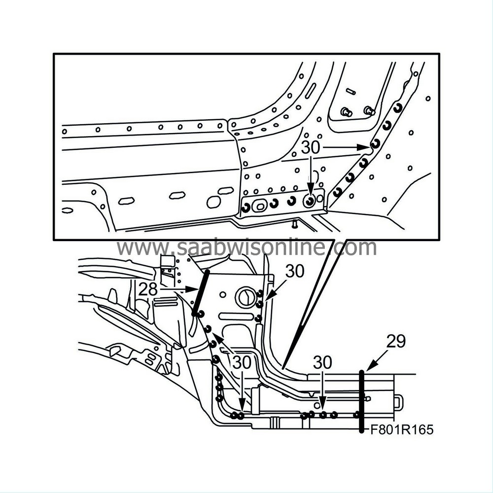
Make a precise cut on the lower A-pillar inner panel with a laser welder.
|
|
| 29. |
Cut the upper A-pillar inner panel as illustrated.
|
|
| 30. |
Drill out the spot welds to the lower A-pillar inner panel as illustrated.
|
|
| 31. |
Tap the lower A-pillar inner panel loose together with the inner sill section.
|
|
| 32. |
Make a precise cut on the replacement panel for the lower A-pillar inner panel with a laser welder.
|
|
| 33. |
Cut the replacement panel for the inner sill as indicated by the marks.

|
|
| 34. |
Drill holes for plug welding in the replacement panel for the inner sill.
|
|
| 35. |
Drill holes for plug welding in the replacement panel for the A-pillar's lower inner panel.
|
|
| 36. |
Grind clean the surfaces that are to be welded.
|
|
| 37. |
Apply welding primer to the surfaces to be spot and plug welded. Use Teroson Zink Spray.
|
|
| 38. |
Place the lower A-pillar inner panel and the inner sill section in fitting position on the body. Align exactly and secure with welding clamps.
|
||||||||||
| 39. |
All-weld the lower edge of the inner sill panel.

|
|
| 40. |
All-weld the upper edge of the inner sill panel.
|
|
| 41. |
Spot and plug weld the lower A-pillar inner panel and the inner sill section.
|
|
| 42. |
Spot and plug weld the lower inner panel to the bulkhead wall and floor.
|
|
| 43. |
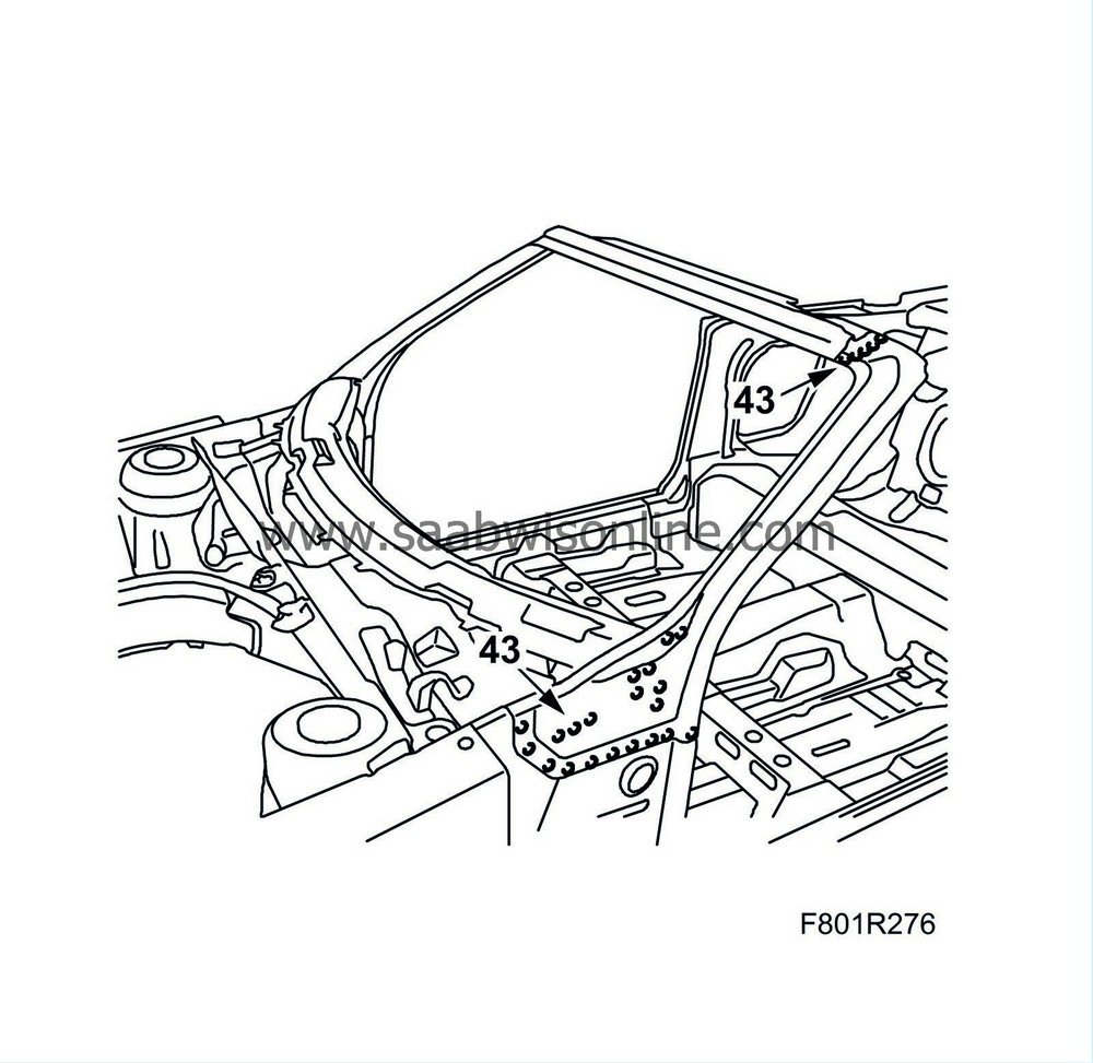
Drill holes for plug welding in the new upper A-pillar inner panel.
|
|
| 44. |
Apply welding primer to the surfaces to be spot and plug welded. Use Teroson Zink Spray.
|
|
| 45. |
Place the upper A-pillar inner panel in fitting position; align it exactly and secure it with some spot welds.
|
||||||||||
| 46. |
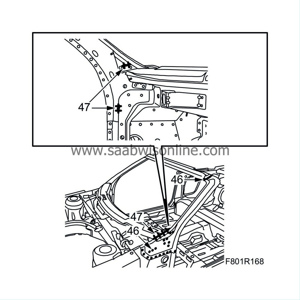
Spot and plug weld the upper A-pillar inner panel at the top and bottom.
|
|
| 47. |
Seam weld the upper A-pillar inner panel on the outside and inside.
|
|
| 49. |
Apply welding primer to the surfaces to be spot and plug welded. Use Teroson Zink Spray.
|
|
| 50. |
Place the centre A-pillar in fitting position on the body; align it exactly and secure it with welding clamps.
|
|
| 51. |
Plug weld the centre A-pillar.

|
||||||||||||||||
| 52. |
Seam weld the centre A-pillar at the top near the windscreen frame.
|
|
| 53. |
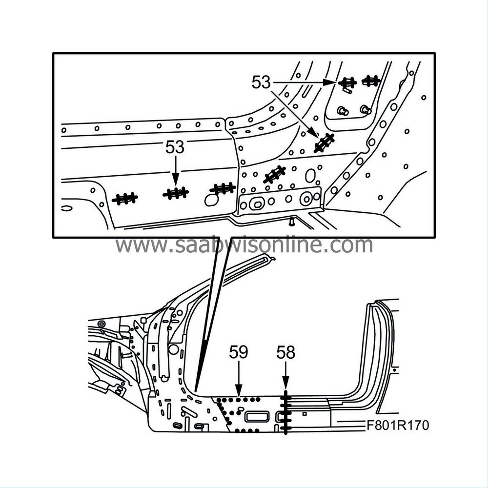
All-weld the support to the lower inner A-pillar near the welding slits.
|
|
| 54. |
Cut the replacement panel for the new centre section of the sill so that it matches the previous cutting.
|
|
| 55. |
Drill holes for plug welding in the replacement panel for the centre sill section.
|
|
| 56. |
Apply welding primer to the surfaces to be spot and plug welded. Use Teroson Zink Spray.
|
|
| 57. |
Place the replacement panel for the centre sill section in fitting position; align it exactly and secure it with welding clamps.
|
|
| 58. |
All-weld the centre sill section.
|
|
| 59. |
Spot and plug weld the centre sill section.
|
|
| 60. |
Place the new support for the hinge reinforcement in fitting position on the body.
Secure with some spot welds.
|
||||||||||
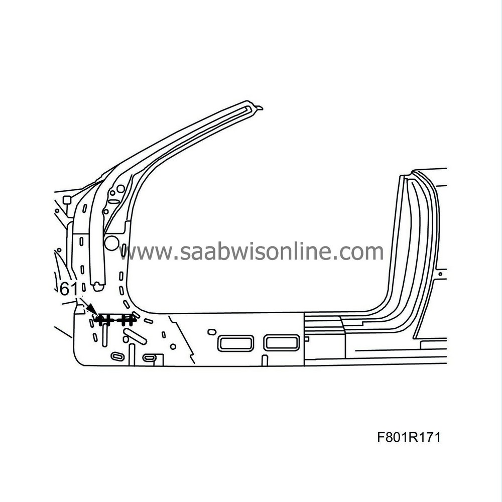
| 61. |
Seam weld the support for the hinge reinforcement on the centre A-pillar.
|
|
| 62. |
Drill holes in the hinge reinforcement for plug welding to the support. Place the new hinge reinforcement in fitting position on the body; align it exactly and secure it with some spot welds.
|
|
| 63. |
Place the door and front wing in fitting position. Re-check the position of the hinge reinforcement.
|
|
| 64. |
Lift aside the door and the front wing.
|
|
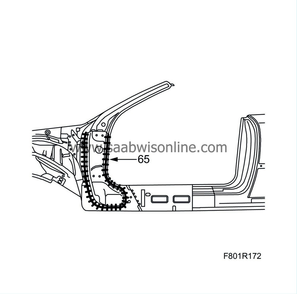
| 65. |
Seam weld the hinge reinforcement all the way around with 10 mm long welds every 10 mm.
|
|
| 66. |
Cut the replacement panel for the front sill so that it matches the old sill exactly.
|
|
| 67. |
Align the front sill on the body and secure it with welding clamps.
|
|
| 68. |
Align the front wing, bonnet and door. Align the front sill exactly.
|
|
| 69. |
Lift aside the front wing, bonnet and door.
|
|
| 70. |
Lift aside the front sill.
|
|
| 71. |
Grind clean the surfaces that are to be welded.
|
|
| 72. |
Drill holes for plug welding in the front sill.

|
|||||||
| 73. |
Apply welding primer to the surfaces to be spot and plug welded. Use Teroson Zink Spray
|
|
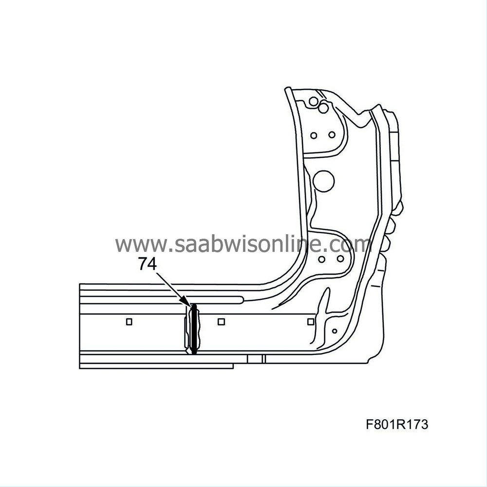
| 74. |
Apply body adhesive to the bulkhead on the new front sill section. Use Teromix 6700.
|
|
| 75. |
Place the front sill in fitting position on the body and secure it with welding clamps.
|
|
| 76. |
Fit and tighten the bolts near the door hinge mountings and the door catch arm mountings.
|
||||||||||
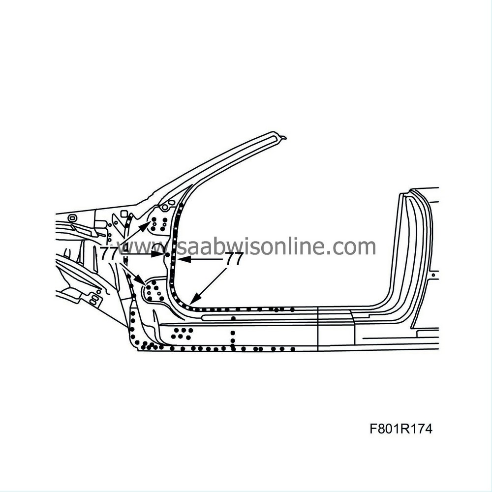
| 77. |
Spot and plug weld the front sill.
|
||||||||||||||||
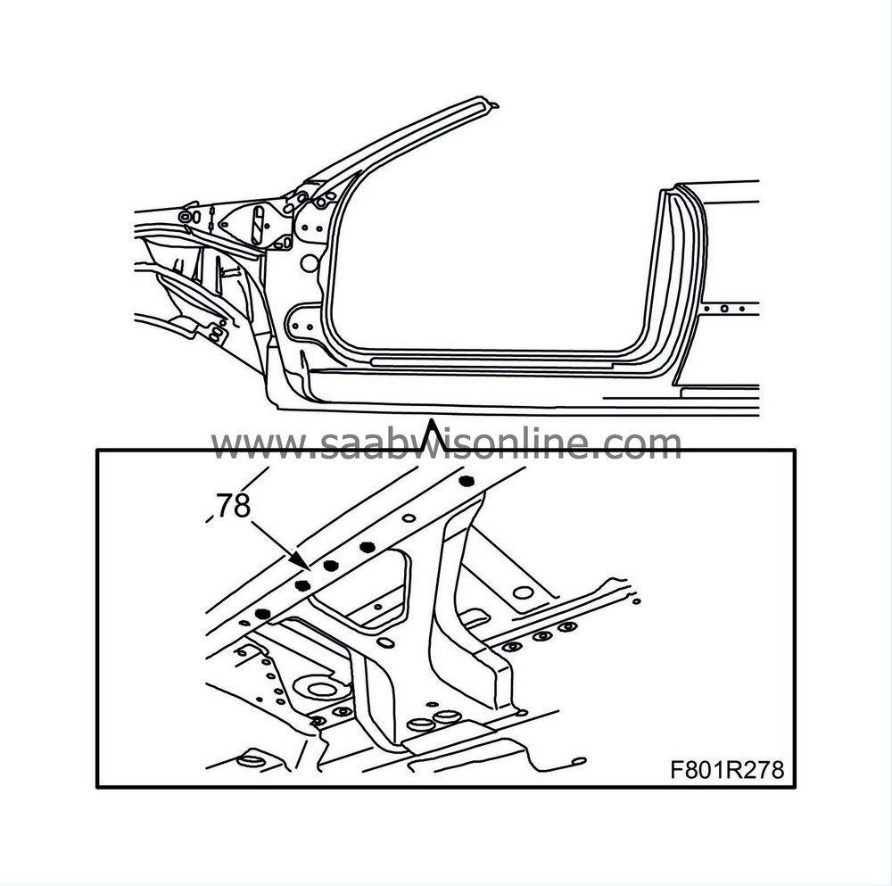
| 78. |
Plug weld the floor reinforcement in place.
|
|
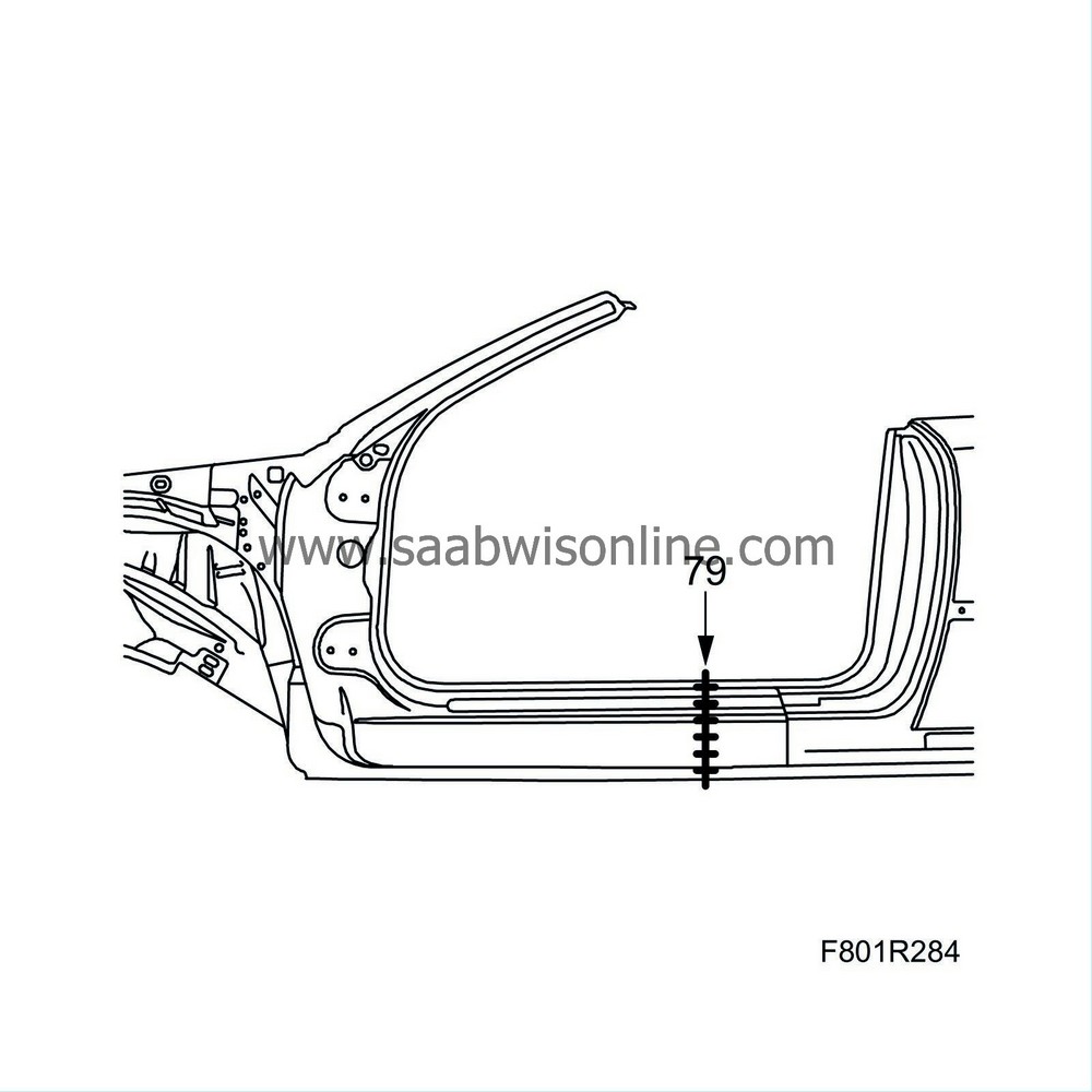
| 79. |
All-weld as illustrated.
|
|
| 80. |
Grind the weld.
|
|
| 81. |
Cut the windscreen frame outer panel so that it matches the previous cutting.
|
|
| 82. |
Place the windscreen frame outer panel in fitting position and secure it with welding clamps.
|
|
| 83. |
Mark the locations for the plug weld holes on the windscreen frame outer panel.
When body adhesive cannot be used between the panel sections, reduce the distance between the spot welds. Spot weld distance max. 25 mm. |
|||||||||||||
| 84. |
Lift aside the windscreen frame outer panel.
|
|
| 85. |
Grind all the surfaces that are to be welded.
|
|
| 86. |
Drill holes for plug welding in the windscreen frame outer panel.
|
|
| 87. |
Apply welding primer to the surfaces to be plug welded. Use Teroson Zink Spray
|
|
| 88. |
Place the windscreen frame outer panel in fitting position and secure it with welding clamps.
|
|
| 89. |
Plug weld the windscreen frame outer panel.

|
||||||||||
| 90. |
All-weld as illustrated.
|
|
| 91. |
Seam weld the windscreen frame outer panel on the bottom.
|
|
| 92. |
Grind the welds.
|
|
| 93. |
Drill holes for plug welding in the replacement panel for the front wheel housing reinforcement.
|
|
| 94. |
Apply welding primer to the surfaces to be spot or plug welded.
|
|
| 95. |
Apply anti-corrosion treatment in the hole as illustrated to provide access to the area before the reinforcement is mounted.

|
|
| 96. |
Place the reinforcement in position. Spot and plug weld.

|
|||||||||
| 97. |
Seam weld and continuous weld the reinforcement as illustrated. The welds must be MIG brazed.
|
|
| 98. |
Wash away surplus welding primer. Welding primer reduces the adhesion of paint, filler and sealant.
|
|
| 99. |
Apply primer to all bare metal surfaces. Use Standox 1K.
|
|
| 100. |
Use Terostat 1K-PUR to seal joints and metal folds.
|
|
| 101. |
Apply anti-corrosion agent to internal surfaces after painting. Use Terotex HV 400.
Fit the Front wing , Bonnet and Front door . |
|

 Warning


