Cylinder head in-car, Z19DT
| Cylinder head in-car, Z19DT |
|
||||||||||||||||||||||
| Important | ||
|
Be very thorough in terms of cleanliness when working in the fuel system. Malfunctions can also occur due to very small dirt particles. Prevent dirt from entering the fuel system by cleaning the hoses and plugging the pipes and lines upon removal using 93 161 370 Plug set. Store the components so that contaminants cannot enter. |
||
| Important | ||
|
Always use wing covers when working in the engine bay. |
||
| To remove |
|
|||||||
|
|||||||||||||
|
|||||||
| 1. |
Disconnect the negative cable from the battery.
|
|
| 2. |
Remove the timing belt
.
|
|
| 3. |
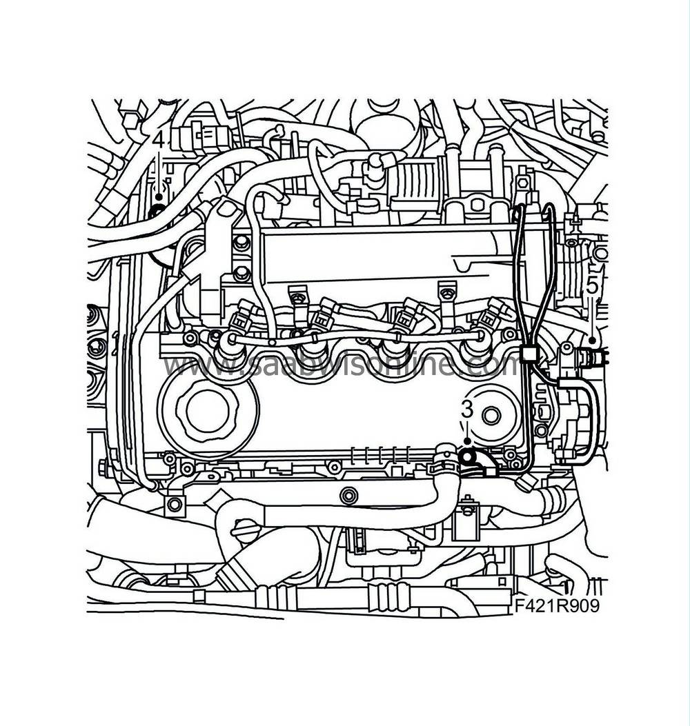
Remove the vacuum pipe from the camshaft cover and intake manifold.
|
|
| 4. |
Remove the ventilation pipe screw.
|
|
| 5. |
Remove the vacuum pump pipe connection and move aside.
|
|
| 6. |
Remove the heat shield over the exhaust manifold
.
|
|
| 7. |
Remove the connectors from
|
|
| • |
Fuel rail pressure sensor (653)
|
| • |
Fuel rail solenoid valve (652a)
|
| • |
Throttle body actuator unit (604)
|
| • |
Coolant temperature sensor (202)
|
| • |
EGR solenoid valve (606)
|
| • |
Intake air sensor (688)
|
| • |
Injectors (206a-d)
|
| 8. |
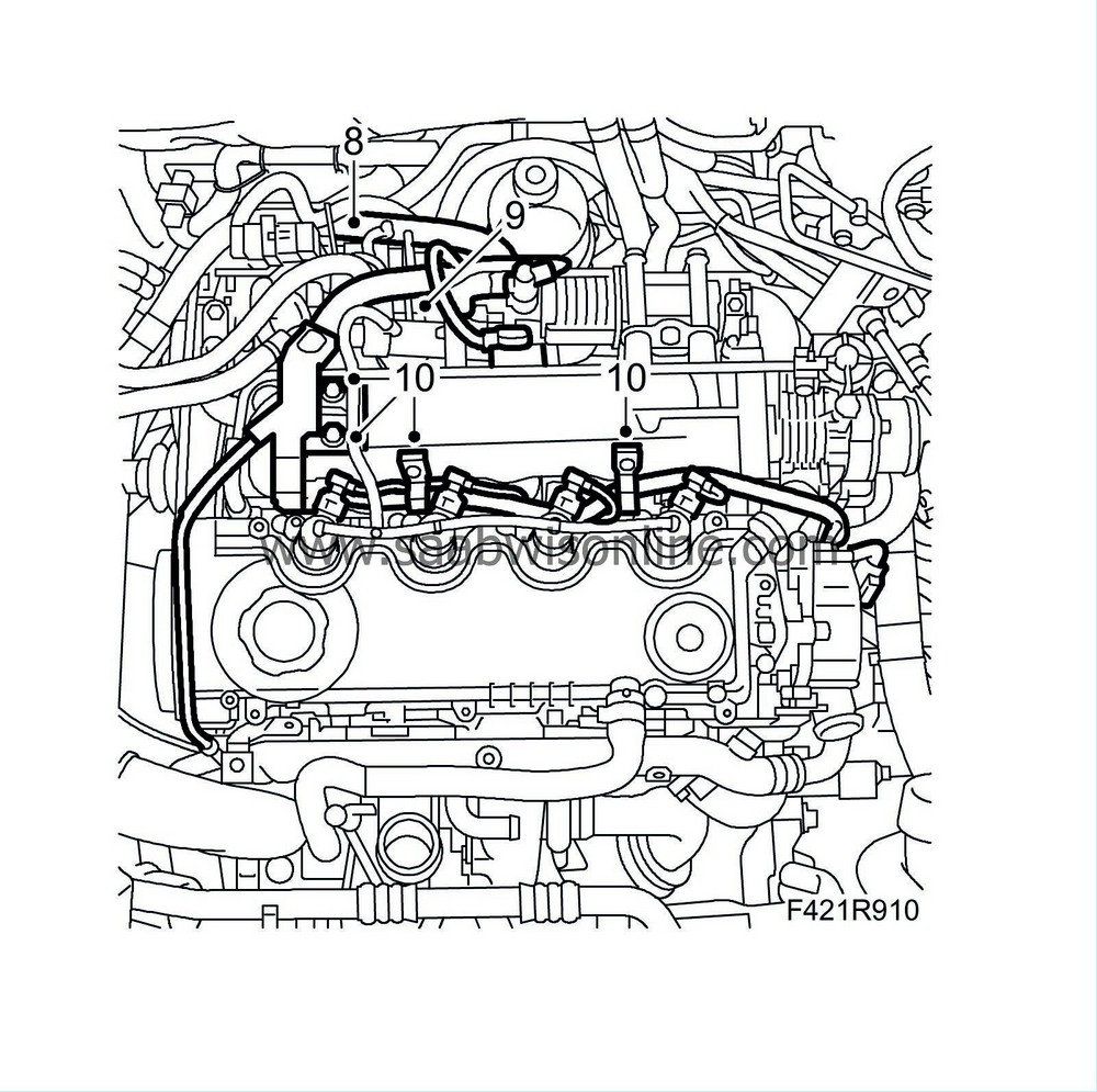
Remove the camshaft position sensor connector and lay the cable on the cylinder head.
|
|
| 9. |
Unplug the connector to the glow plug control module.
|
|
| 10. |
Detach the wiring harness from the intake manifold and move it aside.
|
|
| 11. |
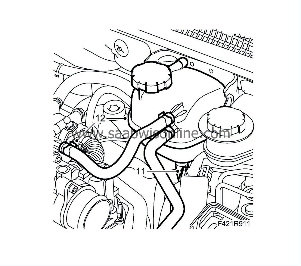
Remove the coolant level switch connector.
|
|
| 12. |
Remove the coolant reservoir and its hose connection on the cylinder head.
|
|
| 13. |
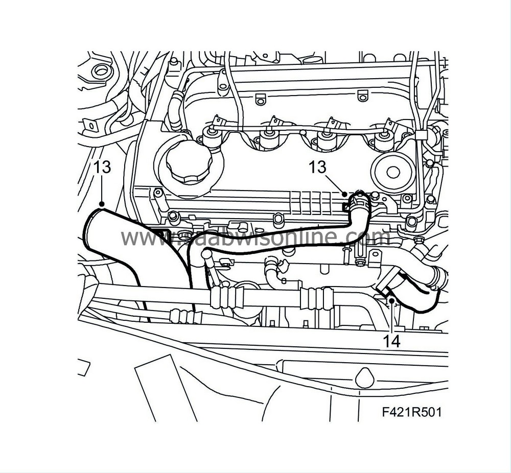
Remove the turbo intake pipe and ventilation hose from the camshaft cover.
|
|
| 14. |
Remove the EGR valve from the exhaust manifold.
|
|
| 15. |
Raise the car.
|
|
| 16. |
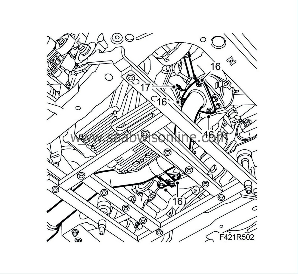
Detach the front exhaust pipe from the front catalytic converter and gearbox, lower the pipe onto the centering fixture.
|
|
| 17. |
Detach the turbo oil return pipe from the engine block.
|
|
| 18. |
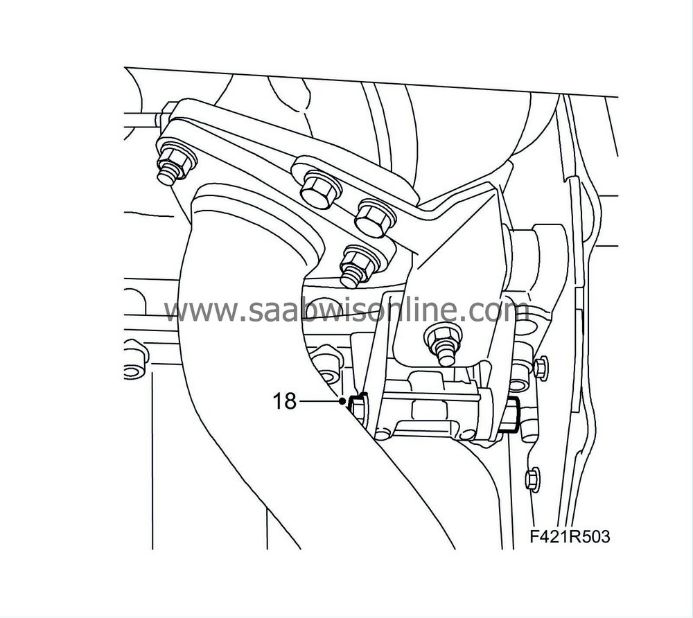
Loosen the bottom bracket on the catalytic converter slightly.
|
|
| 19. |
Lower the car.
|
|
| 20. |
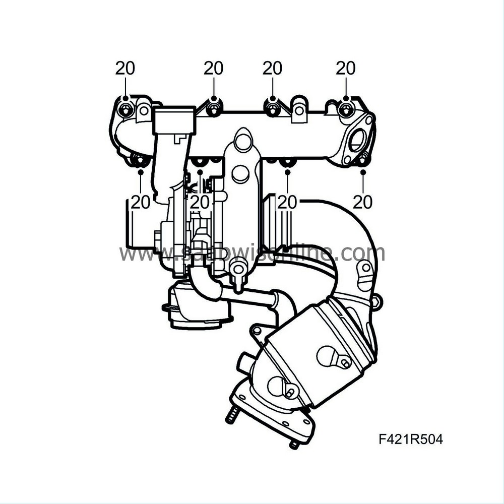
Remove the exhaust manifold nuts and carefully angle it out so the studs go free.
|
|
| 21. |
Remove the nuts holding the pipe to the starter motor bracket.
|
|
| 22. |
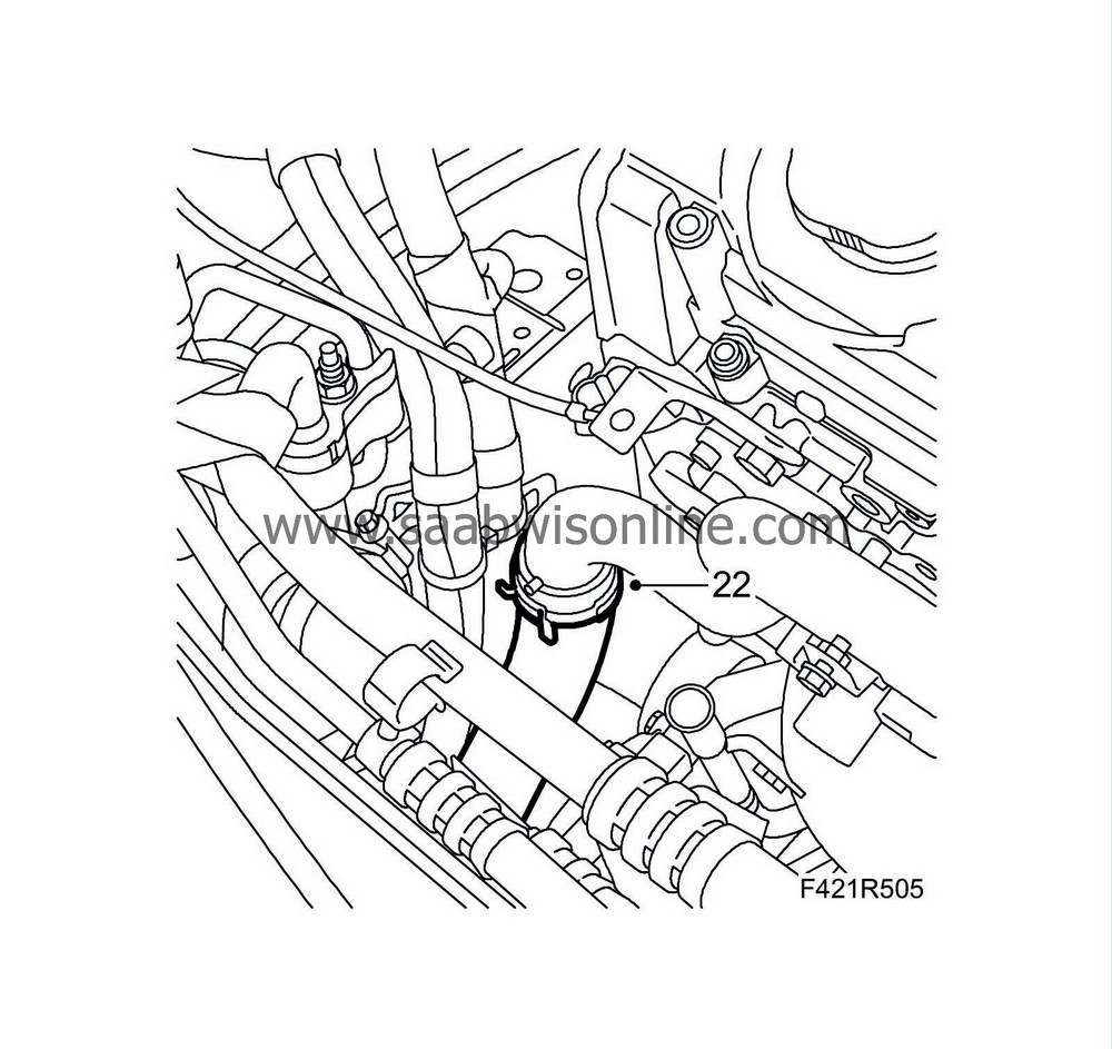
Detach the lower coolant hose from the coolant pipe.
|
|
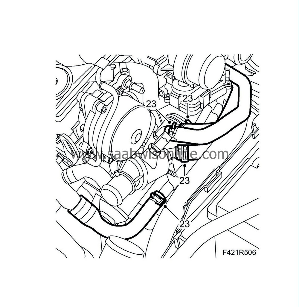
| 23. |
Undo the coolant hoses on the thermostat housing and EGR cooler. Place a receptacle underneath the car.
|
|
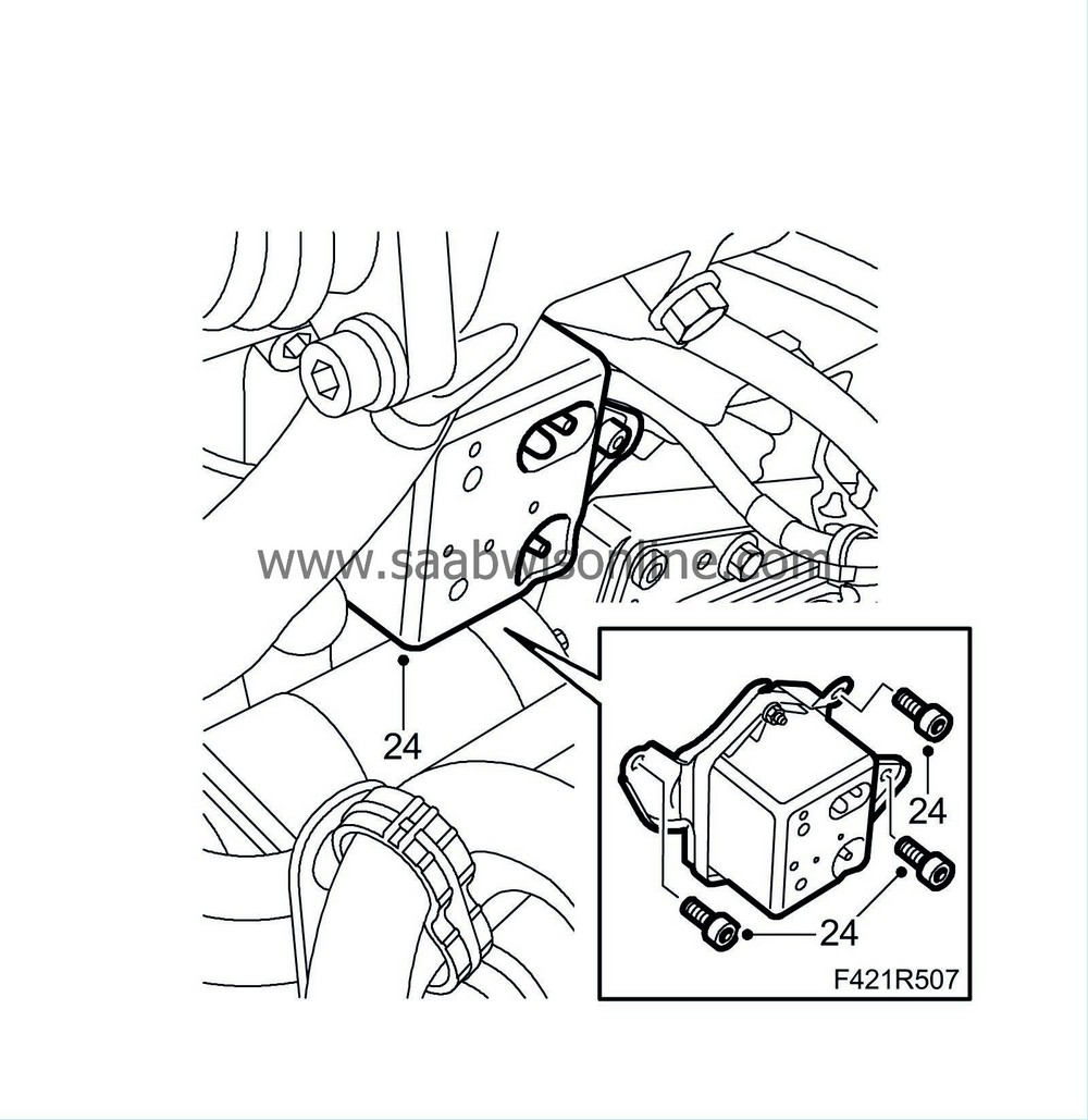
| 24. |
Dismantle the vacuum container complete with bracket.
|
|
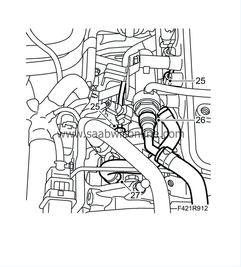
| 25. |
Remove the fuel pipe between the high pressure fuel pump and the fuel rail, plug the connections.
|
|
| 26. |
Detach the return fuel line from the return fuel collector and plug the connections.
|
|
| 27. |
Detach the return fuel hose from the high pressure fuel pump and plug the connections.
|
|
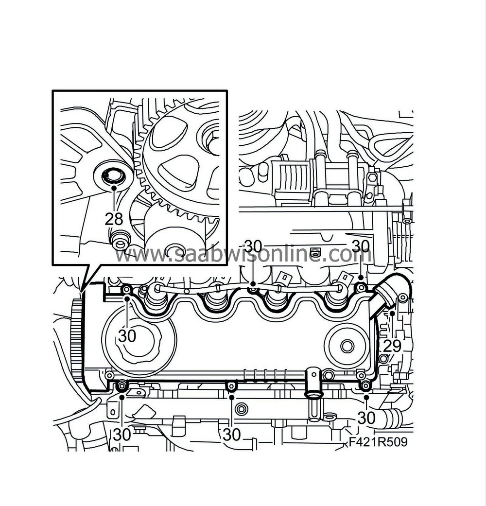
| 28. |
Remove the bolt adjacent to the camshaft sprocket. Screw back the spacer sleeve so the cylinder head goes free.
|
|
| 29. |
Detach the crankcase ventilation hose and let it down.
|
|
| 30. |
Remove the camshaft cover.
|
|
| 31. |
Unscrew and remove the cylinder head bolts in the illustrated order.

|
|
| 32. |
Carefully lift off the cylinder head.
|
|
| To fit |
| 1. |
Clean the bolt holes in the cylinder block.
|
|
| 2. |
Clean away any gasket remains from the cylinder head and cylinder block sealing surfaces.
|
|
| 3. |
Check the flatness of the cylinder head and cylinder block with a steel rule and inspect for damage to the sealing surfaces.
|
|
| 4. |
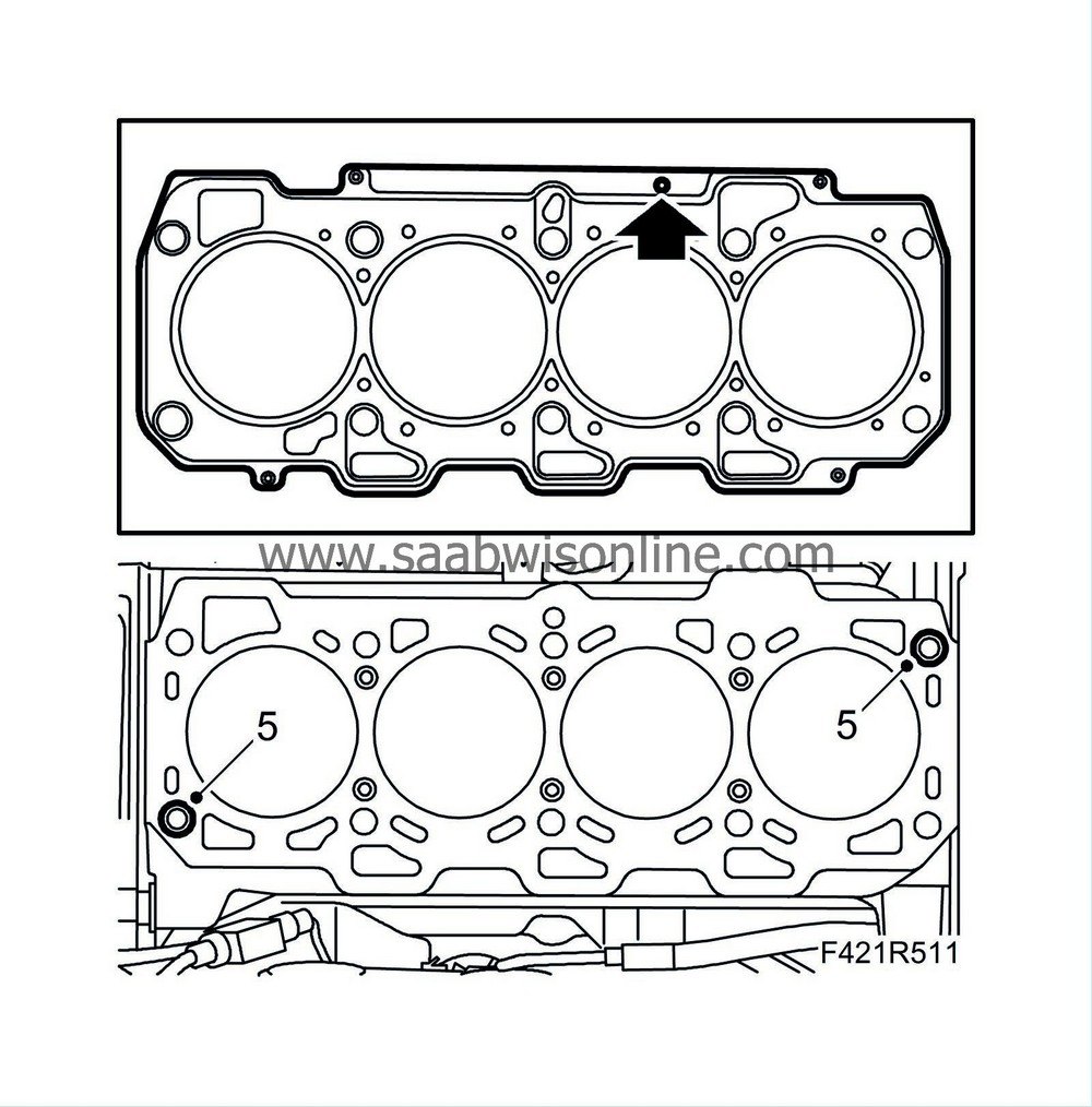
Fit a new gasket with the same thickness as the old one.
|
|
| 5. |
Place the guide sleeves on the engine block.
|
|
| 6. |
Position the cylinder head on the cylinder block.
|
|
| 7. |
Tighten the cylinder head bolts in the illustrated order.
Tightening torque Stage I 65 Nm (48 lbf ft) Stage II +90° Stage III +90° Stage IV +90° 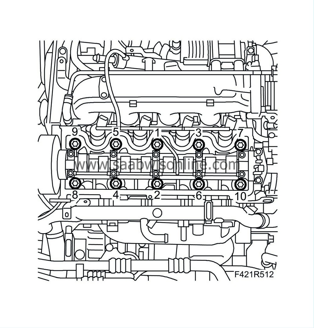
|
|
| 8. |
Fit the camshaft cover with a new gasket.

|
|
| 9. |
Lift up the crankcase ventilation hose and connect it.
|
|
| 10. |
Screw in the spacer sleeve against the cylinder head and fit the bolt.
|
|
| 11. |
Fit the return fuel hose to the fuel pump.
|
|
| 12. |
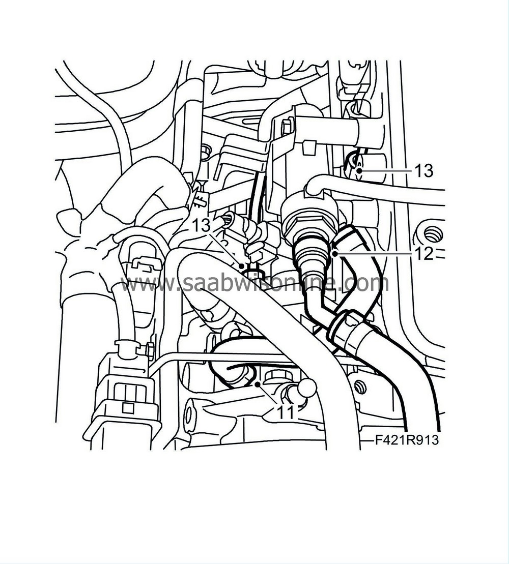
Fit the return fuel line to the return fuel collector.
|
|
| 13. |
Fit the fuel pipe between the fuel pump and the fuel rail. Put on the nuts by hand. If it is difficult to get the fuel pipe in place, unscrew the nuts on the fuel rail slightly.
Tightening torque, fuel pipe 25 Nm (18 lbf ft) Tightening torque, fuel rail 25 Nm (18 lbf ft). |
|
| 14. |
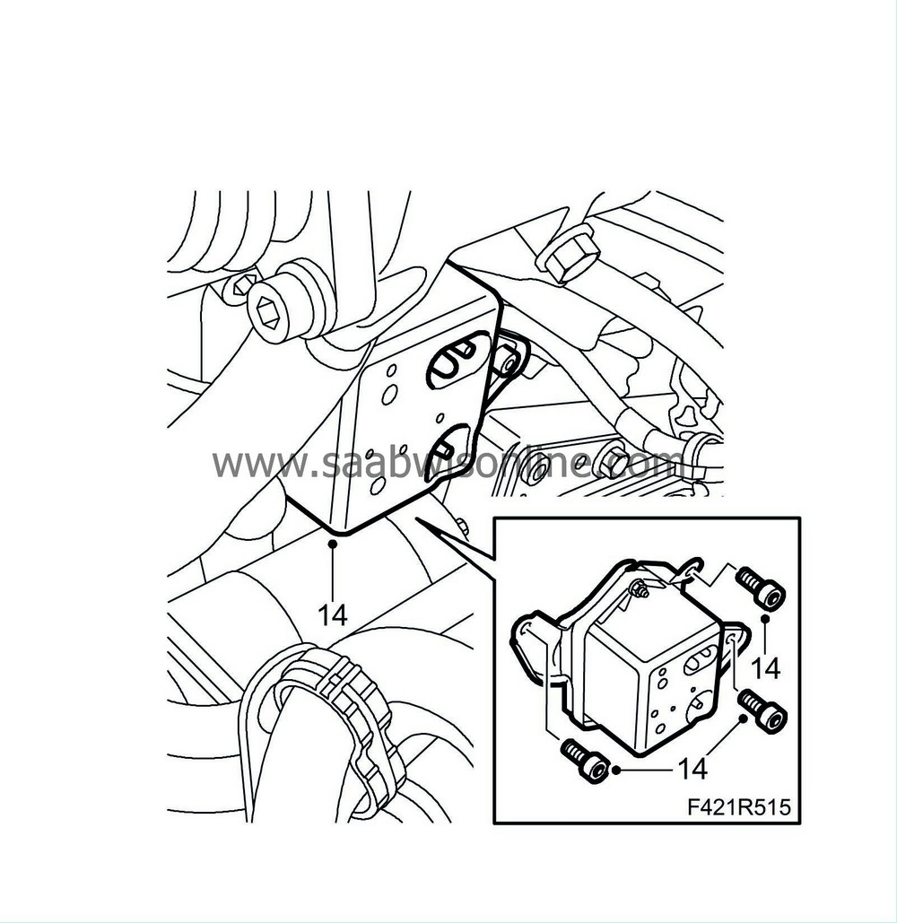
Fit the vacuum container.
|
|
| 15. |
Fit the coolant hoses on the thermostat housing and the EGR cooler.
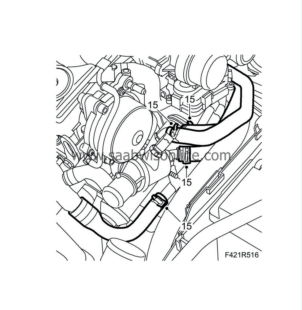
|
|
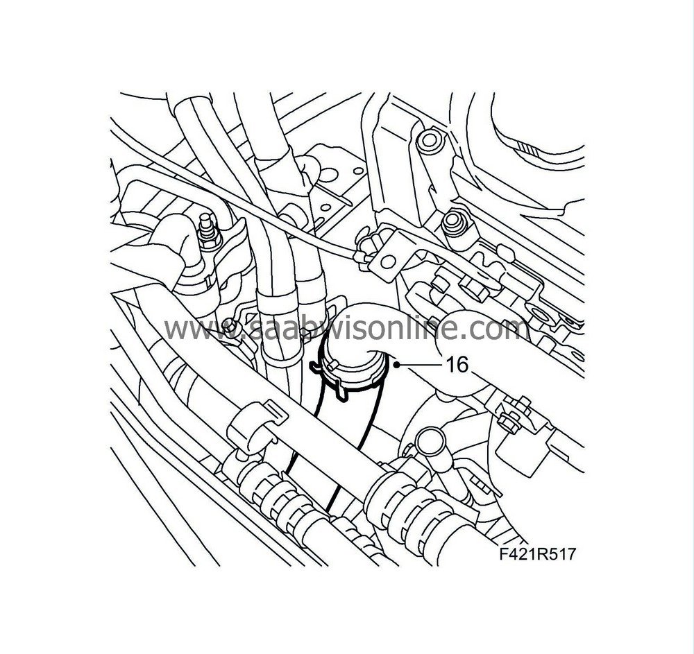
| 16. |
Fit the lower coolant hose to the coolant pipe.
|
|
| 17. |
Fit the nuts holding the pipe to the starter motor bracket.
|
|
| 18. |
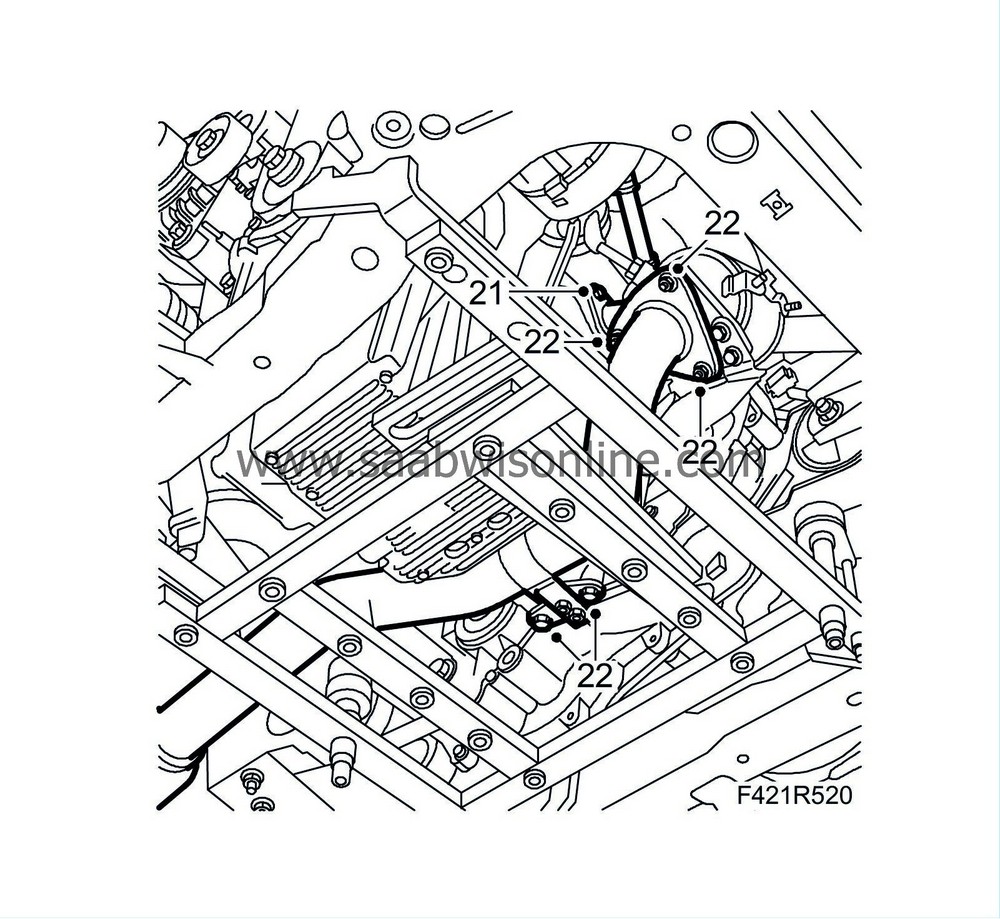
Put on a new gasket and lift up the exhaust manifold. Fit the nuts.
Tightening torque 20 Nm (15 lbf ft) 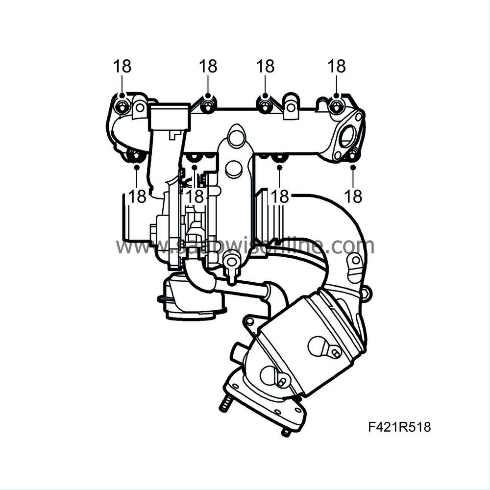
|
|
| 19. |
Raise the car.
|
|
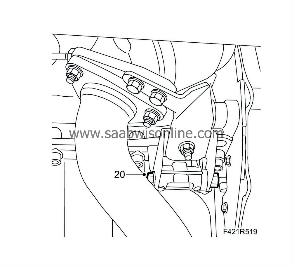
| 20. |
Tighten the front catalytic converter bracket.
|
|
| 21. |
Fit the turbo return oil pipe with a new gasket.
|
|
| 22. |
Fit the front exhaust pipe with a new gasket.
|
|
| 23. |
Lower the car.
|
|
| 24. |
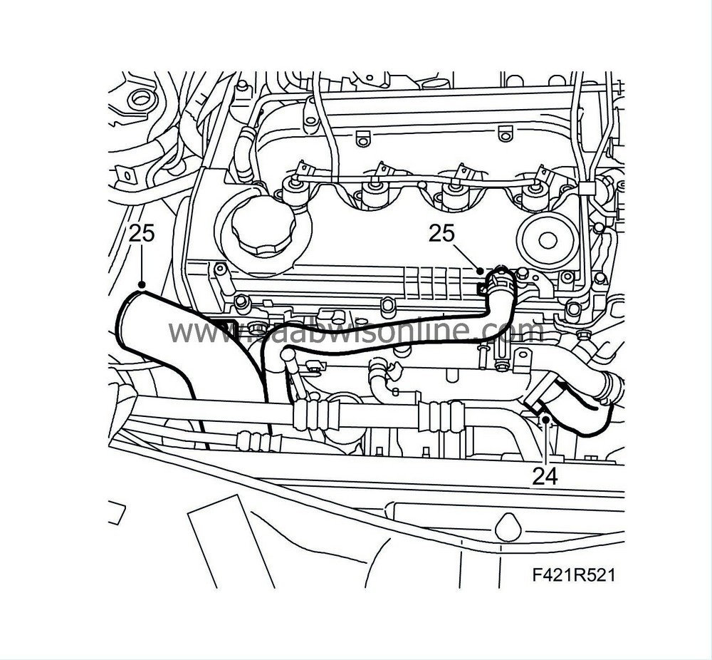
Fit the EGR pipe with a new gasket.
|
|
| 25. |
Fit the turbo intake pipe and the ventilation hose on the camshaft cover.
|
|
| 26. |
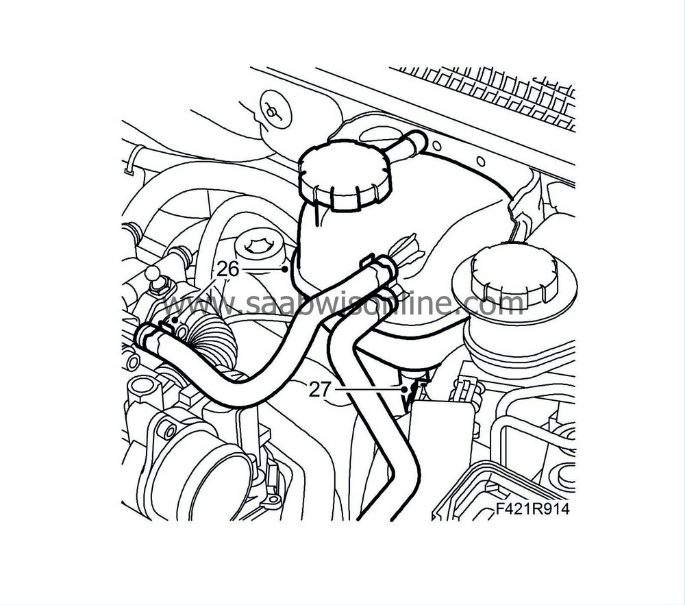
Fit the coolant reservoir on the bulkhead and attach the hose.
|
|
| 27. |
Plug in the coolant level switch connector.
|
|
| 28. |
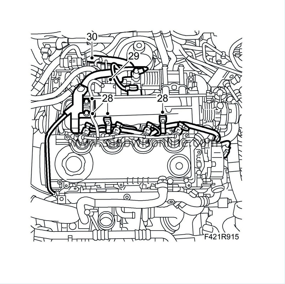
Fit the wiring harness to the intake manifold.
|
|
| 29. |
Plug in the connector to the glow plug control module wiring harness.
|
|
| 30. |
Plug in the camshaft position sensor connector.
|
|
| 31. |
Fit the connectors on
|
|
| • |
Fuel rail pressure sensor (653)
|
| • |
Fuel rail solenoid valve (652a)
|
| • |
Throttle body actuator unit (604)
|
| • |
Coolant temperature sensor (202)
|
| • |
EGR solenoid valve (606)
|
| • |
Intake air sensor (688)
|
| • |
Injectors (206a-d)
|
| 32. |
Fit the heat shield over the exhaust manifold
.
|
|
| 33. |
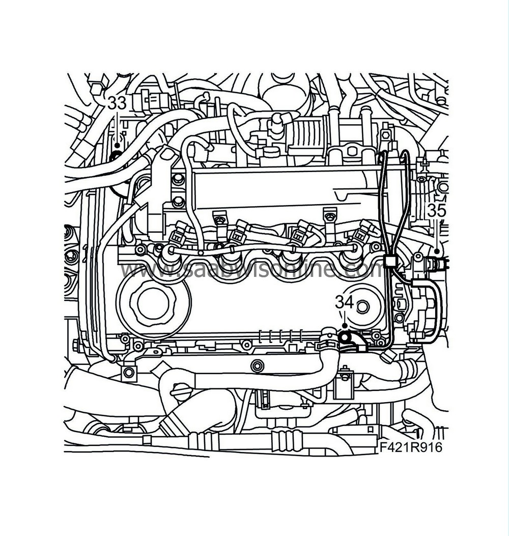
Fit the ventilation pipe screw.
|
|
| 34. |
Fit the vacuum pipe to the camshaft cover and intake manifold.
|
|
| 35. |
Fit the vacuum pump pipe connection.
|
|
| 36. |
Fit the timing belt
.
|
|
| 37. |
Fill with coolant.
|
|
| 38. |
Change oil and filter.
|
|
| 39. |
Connect the negative battery cable and fit the battery cover.
|
|
| 40. |
Remove the covers from the wings and return the electrical system to its original state. Refer to
Procedures after reconnecting the battery
.
|
|
| 41. |
Connect an exhaust hose and start the engine. Check that there are no leaks.
Connect the diagnostic tool and erase any diagnostic trouble codes. |
|
| 42. |
Fit the engine cover.
|
|

 Warning

