Short description
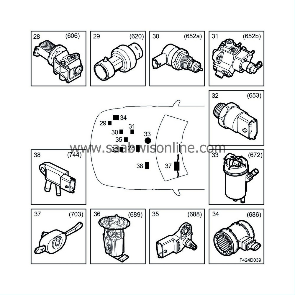
| Short description |
| 1. |
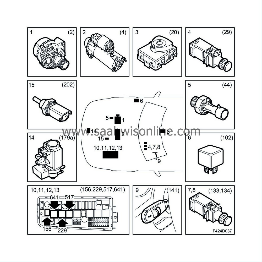
Generator (2)
|
|
| 2. |
Starter motor (4)
|
|
| 3. |
Ignition switch unit (20)
|
|
| 4. |
Brake light switch (29)
|
|
| 5. |
Pressure monitor, engine oil (44)
|
|
| 6. |
Relay, fuel pump (102)
|
|
| 7. |
Clutch switch, cruise control (133)
|
|
| 8. |
Brake switch, cruise control (134)
|
|
| 9. |
Cruise control switch (141, included in 703)
|
|
| 10. |
Relay, A/C compressor (156)
|
|
| 11. |
Main relay, engine management system (229)
|
|
| 12. |
Relay, +50 (517)
|
|
| 13. |
Diesel preheating relay (641)
|
|
| 14. |
Boost pressure control valve (179a)
|
|
| 15. |
Coolant temperature sensor (202)
|
|
| 16. |
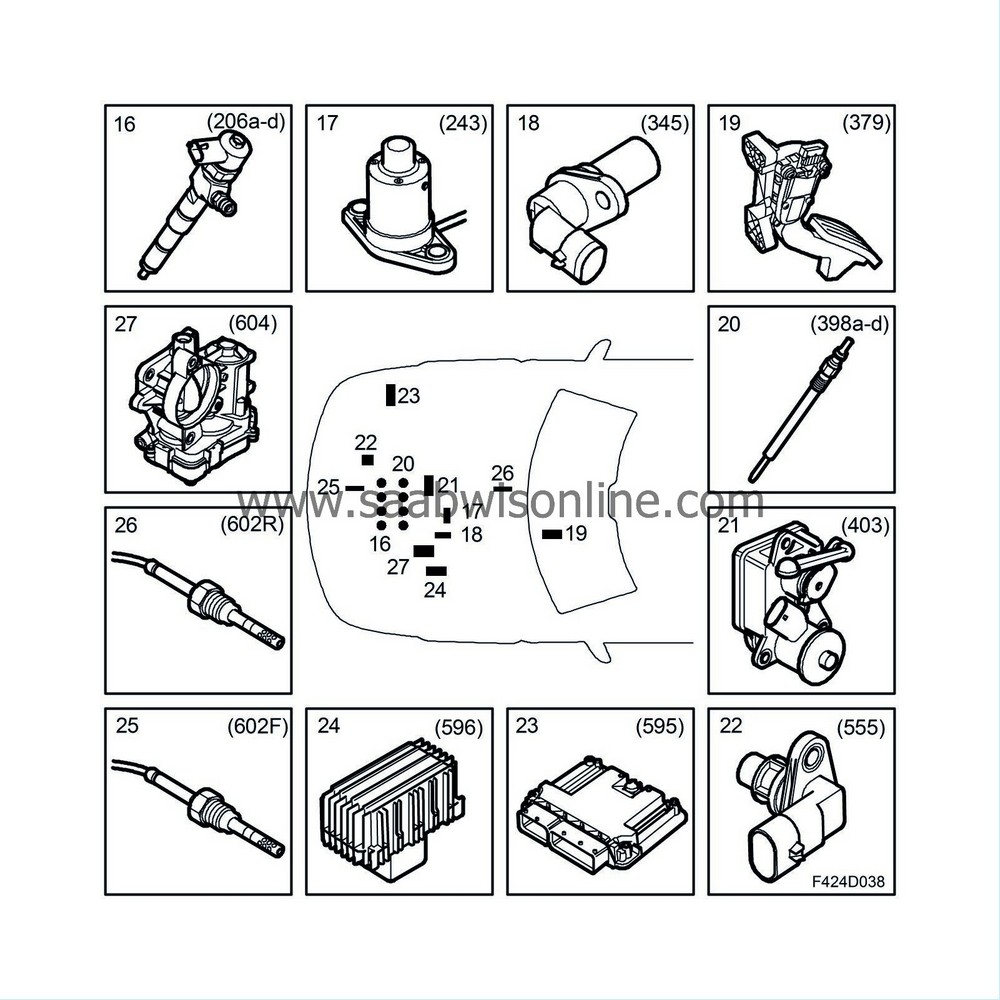
Injectors (206a-d)
|
|
| 17. |
Level sensor, engine oil (243)
|
|
| 18. |
Crankshaft position sensor (345)
|
|
| 19. |
Accelerator pedal position sensor (379)
|
|
| 20. |
Glow plugs (398a-d)
|
|
| 21. |
Actuator, combustion circulation (403)
|
|
| 22. |
Camshaft position sensor (555)
|
|
| 23. |
EDC16 control module (595)
|
|
| 24. |
Control module, glow plugs (596)
|
|
| 25. |
Front exhaust temperature sensor (602F)
|
|
| 26. |
Rear exhaust temperature sensor (602R)
|
|
| 27. |
Throttle body actuator unit (604)
|
|
| 28. |
EGR solenoid valve (606)
|
|
| 29. |
A/C pressure sensor (620)
|
|
| 30. |
Fuel pressure control valve, fuel rail (652a)
|
|
| 31. |
Fuel quantity control valve, high-pressure pump (652b)
|
|
| 32. |
Fuel pressure sensor, fuel rail (653)
|
|
| 33. |
Diesel fuel filter unit (672) contains:
|
|
| • |
Heating element, fuel filter (410)
|
| • |
Fuel temperature sensor (651)
|
| • |
Fuel filter water level switch (692)
|
| 34. |
Mass air flow sensor unit (686) contains:
|
|
| • |
Mass air flow sensor (205)
|
| • |
Mass air flow sensor temperature sensor (772)
|
| 35. |
Intake air sensor (688) contains:
|
|
| • |
Intake air temperature sensor (407)
|
| • |
Charge air pressure sensor (603)
|
| 36. |
Fuel pump unit (689) contains:
|
|
| • |
Level sensor, fuel (46)
|
| • |
Engine, fuel pump (323)
|
| 37. |
Column Integration Module (703, contains 141)
|
|
| 38. |
Particle trap pressure sensor (744)
|
|
| Function |
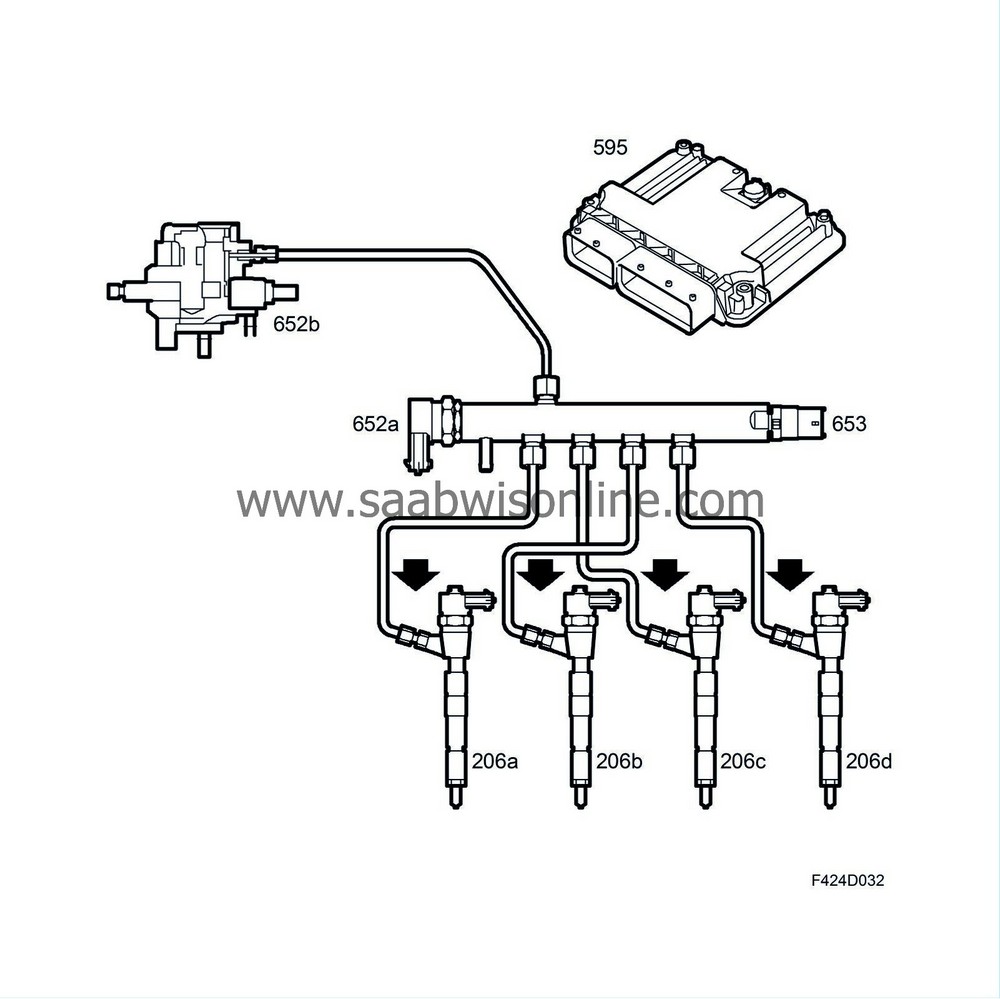
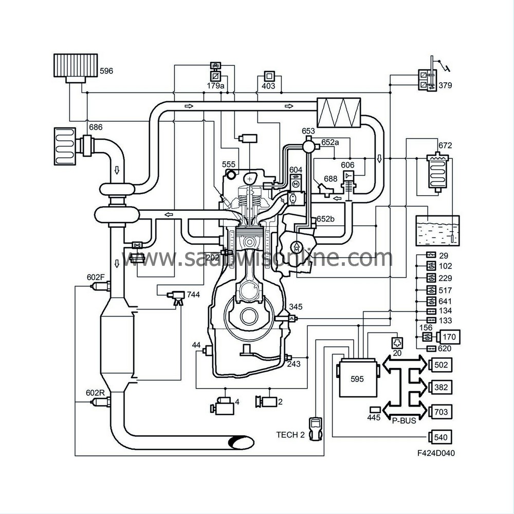
The Bosch EDC16C9 engine management system is used on both engine variants Z19DH and Z19DTH but with different calibration data for each one. The system is of common rail type, i.e. a high-pressure pump feeds a fuel rail to which the electronically controlled fuel injectors are connected with pipes.
The software can be updated with SPS.
The engine management system is used to regulate the amount of fuel injected at the correct time, turbo control and engine torque. When the driver depresses the accelerator pedal, it acts on a pedal position sensor integrated in the pedal bracket. This information in the form of a voltage is converted by ECM to a request for engine torque. This torque request is then processed by ECM taking into account the prevailing running conditions and limitations, with the result forming a fuel request to attain the engine torque requested by ECM.

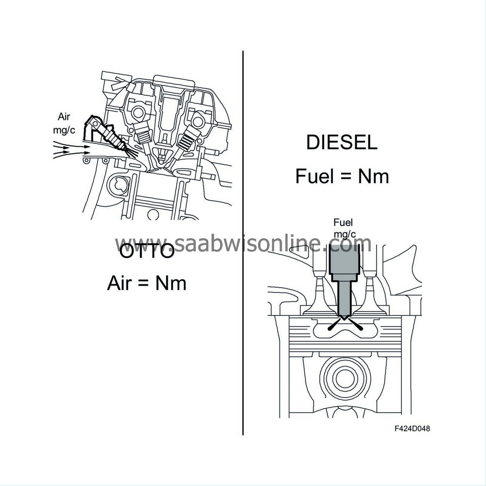
Engine torque is about the same as the injected fuel quantity. ECM controls the flow of air in order to maintain low emissions. If there is not enough air mass per combustion available, black smoke will arise. To avoid this happening, there is a smoke detector function to limit the amount of fuel.
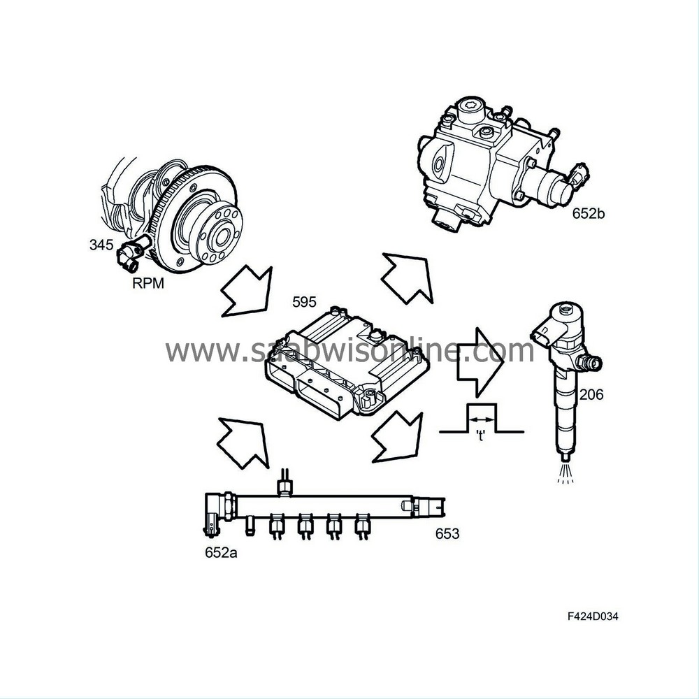
The amount of fuel injected is controlled by regulating the fuel pressure, injection timing and injection duration (crankshaft position) for injection. The control module calculates an optimum injection quantity per combustion and injection duration for all driving conditions with regard to emissions, engine strength, drivability and fuel consumption.
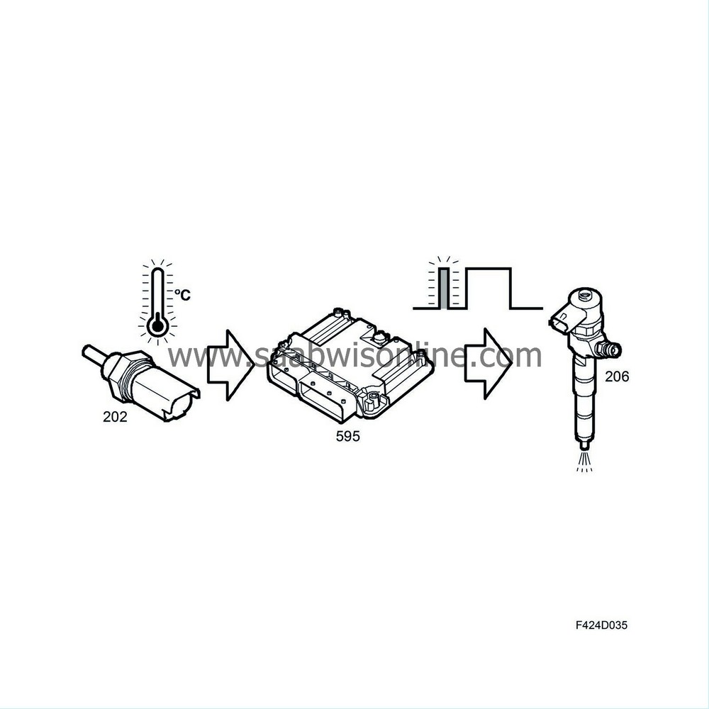
To reduce engine noise at low coolant temperatures a so-called "pilot injection" is used. This means that a small amount of fuel is injected just ahead of the main injection. The function is active when the coolant temperature is below +60°C.
| Description |

EDC16 control module (595)
ECM reads the driver's required power output (torque request) and with the help of several sensors, it calculates the permitted amount of fuel to use in mg/combustion.Its internal diagnosis can be read directly using the diagnostic tool.
ECM also reads the digital information from the cruise control system switch and, if required by the driver, the engine control module will control the speed of the car.
The radiator fan speed is controlled by ECM.
Generator (2)
ECM controls the charge from the generator and compensates for its torque load.When ECM has registered that the engine has started by calculating the engine speed signal, charging will start.
Brake light switch (29)
The switch informs ECM of the brake pedal position. It is used to turn off cruise control.Pressure monitor, engine oil (44)
If there is no oil pressure, the switch will close and ground ECM, which in turn sends a bus message "no oil pressure" to MIU and SID.Relay, fuel pump (102)
The relay is activated by ECM when it is time to start the fuel pump.Clutch switch, cruise control (133)
The switch informs ECM of the clutch pedal position. It is used to turn off cruise control.Brake switch, cruise control (134)
The switch is used to carry out a feasibility assessment of the brake light switch. It is also used to turn off the cruise control.Relay, A/C compressor (156)
The relay controls engagement and disengagement of the A/C compressor after a command from ECM. Meanwhile, ECM will compensate for the increase/decrease in engine torque requirements.Boost pressure control valve (179a)
The solenoid valve controls the boost pressure with the help of vacuum from the vacuum pump. The time of engagement is controlled with a PWM signal from ECM.Temperature sensor, coolant, engine management system (202)
The temperature sensor measures the engine temperature. ECM uses the reading to deliver more fuel to the engine when the engine is cold. In addition, it can protect the engine against harmful overheating because the control module will limit the amount of fuel if there is a risk of overheating. The speed of the radiator fans is controlled by the engine temperature.Injectors (206)
Injects the amount of fuel calculated by ECM into the cylinder.Main relay, engine management system (229)
The relay controls the power supply to most of the engine management system components.Level sensor, engine oil (243)
The sensor switch opens when the oil level becomes too low. ECM confirms that the level is low by evaluating the time during which the switch has been open.ECM then sends bus message "Oil level low" to SID. The information from the oil level sensor is a filtered value depending on temperature, engine speed, acceleration and vehicle speed to give a mean value for the oil level.
Crankshaft position sensor (345)
The position sensor sends an A/C voltage with a frequency proportional to the engine speed. Each pulse is used by ECM to determine whether the engine is in top dead centre.Accelerator pedal position sensor (379)
The position sensor has two potentiometers that inform the ECM of the driver's torque request.Glow plugs (398)
Gives the fuel the correct ignition temperature if necessary.Swirl throttle actuator (403)
The actuator regulates the vacuum controlling the swirl throttle.Relay, +50 (517)
When ECM has checked that all the starting conditions have been met, it will activate the relay so that the starter motor cranks.Camshaft position sensor (555)
The position sensor keeps track of the camshaft position so it knows which cylinder is in turn for ignition.Control module, glow plugs (596)
The control module powers the glow plugs on request from the engine control module. In addition, it reduces the output to the glow plugs once the engine has started. The glow plug control module has an internal diagnosis whose result is sent on a wire to ECM, where any diagnostic trouble codes are read.Exhaust temperature sensor (602)
Measures the exhaust temperature before and after the catalytic converters.Throttle body actuator unit (604)
Regulates the amount of air to the combustion chamber.EGR solenoid valve (606)
ECM controls the time the control valve is engaged with a PWM signal. The EGR function means that ECM orders the EGR to allow a certain amount of burned exhaust gas to pass so that the mg/combustion calculated by the control module can be attained.A/C pressure sensor (620)
Measures the prevailing pressure in the high pressure side of the A/C system.Used for load compensation, cooling fan function and sent as a bus message for use by the ACC.
Preheating relay (641)
ECM activates the relay when the fuel must be preheated in the fuel filter.Fuel pressure control valve, fuel rail (652a)
When the pressure in the fuel rail becomes too high in relation to the required pressure, ECM will open the solenoid valve so that excess fuel can drain via the return line.Fuel quantity control valve, high-pressure pump (652b)
The amount of fuel entering the high-pressure pump is controlled by the valve, above all at low engine speeds.Fuel pressure sensor, fuel rail (653)
The fuel rail pressure is measured by the pressure sensor so that ECM can regulate the pressure in the fuel rail and thereby the amount of fuel to the injector.Fuel filter unit (672)
The unit contains the fuel filter heating element (410), fuel temperature sensor (651) and water level switch (692).The heating element preheats the fuel when necessary. ECM controls the heating based on the temperature sensor reading.
The level switch will warn if there is too much water in the filter.
Mass air flow sensor unit (686)
This unit contains the mass air flow sensor (205) and the temperature sensor (772).The mass air flow sensor measures the mass air flow to the engine. ECM calculates the intake air mass per combustion based on the air mass flow.
The temperature sensor measures the temperature of the incoming air.
Intake air sensor (688)
The combined pressure and temperature sensor measures the temperature and pressure of the intake air.The pressure sensor measures the pressure in the intake manifold so that ECM can control the turbocharger boost pressure.
The temperature sensor measures the temperature of the intake air so that ECM can request the correct air mass for combustion (hot air requires a high volume).
Fuel pump unit (689)
The fuel pump unit contains the fuel level sensor (46) and the fuel pump (323).The level sensor measures the amount of fuel in the tank.
The fuel pump works at low pressure and delivers fuel to the high-pressure pump.
CIM (703)
If the transponder code is approved, a signal is sent to the ISM to allow the key to turn. Once this has been done, the engine can be started.With help of the integrated cruise control switch (141) the driver can request that ECM should maintain vehicle speed alternatively reduce or increase the set vehicle speed.
Radiator fan relay unit (706)
Based on the engine temperature reading and the A/C pressure, ECM controls the radiator fan speed via the relay unit.Particle trap pressure sensor (744)
To establish when the particle trap is full and requires emptying, the pressure sensor will measure the differential pressure across the trap.| Principle of operation, 4-stroke diesel engine |
Differences between Otto engine and diesel engine
The greatest difference between a conventional Otto engine and a diesel engine is the way in which fuel is supplied to the engine, the ignition system and the compression ratio.Otto engine

| • |
The fuel is supplied mixed with the intake air
|
|
| • |
Ignition with electric spark
|
|
| • |
Relatively low compression ratio (normally between 8:1 - 12:1)
|
|
Diesel engine

| • |
The fuel is delivered to the combustion chamber where it is mixed with air
|
|
| • |
Ignition with heat of compression
|
|
| • |
Relatively high compression ratio (normally between 16:1 - 22:1)
|
|
The four strokes
The diesel engine is four stroke: intake, compression, power and exhaust.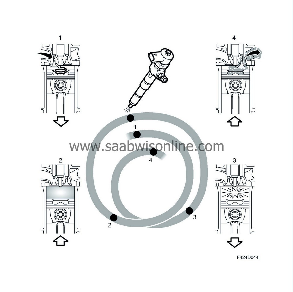
During the intake stroke, air is led into the cylinder and through the shape of the inlet ducts the air starts to swirl vigorously. The inlet valves close and the compression stroke starts.

The enclosed air mass is now compressed and the pressure and temperature increase. When the piston moves up in the cylinder, it will affect the motion of the air and by the end of the compression stroke, in principle all the air from the outer regions of the piston crown will be forced into the space in the piston (combustion chamber). As air moves from the outer regions its speed will increase and at the end of the compression stroke, fuel is added at a pressure of up to 16 Mpa (160 bar).
Combustion takes place in a diesel engine by means of a correct amount of fuel being added to an air mass at high temperature and pressure. The fuel will ignite after a certain delay. This delay is principally dependent on the prevailing pressure, temperature, cetane number of the fuel and how well the fuel is mixed with the air. A short ignition lag should be strived for as this will give a smooth and quiet running.

The piston has now turned, the fuel has ignited and the gas is expanding vigorously, and is on its way down in the cylinder, the power stroke. The pressure in the cylinder is now transformed into useful work. Just before the piston reaches it bottom dead centre, the exhaust valve will open and the exhaust gas passes out into the exhaust manifold for further transport to the turbocharger turbine. This process is repeated.
Efficiency
The diesel engine is considerably more efficient than the conventional Otto engine for many reasons.
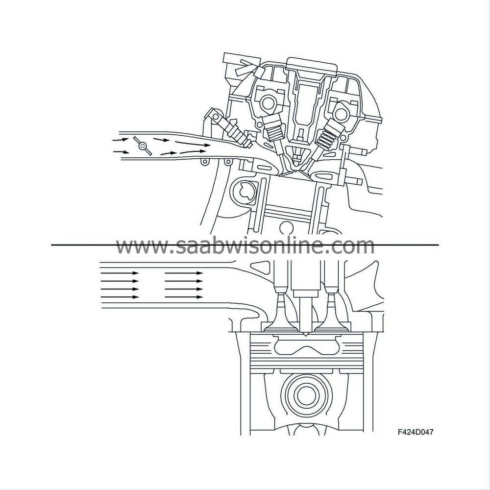
The lack of a throttle means the engine can breath without restriction, giving less pump loss. High compression ratio gives high efficiency but it cannot increase indefinitely. At a certain compression ratio, the losses will be greater than the gains and efficiency will be impaired. The use of a turbocharger with VNT turbine reduces the exhaust back pressure in comparison with the use of a turbocharger with fixed geometry in combination with a wastegate. The lower the exhaust back pressure the smaller the pump losses.
Torque control
Diesel engine power, torque, is regulated by adding the right amount of fuel and from this calculate and add the right air mass. In an Otto engine, this relationship is the opposite, air mass gives torque, the necessary fuel is calculated for the air mass in question.