Short description
| Short description |
| Overview |

| 1. |
Generator (2)
|
|
| 2. |
Starter motor (4)
|
|
| 3. |
Ignition switch unit (20)
|
|
| 4. |
Brake light switch (29)
|
|
| 5. |
Relay, fuel pump (102)
|
|
| 6. |
Clutch switch, cruise control (133)
|
|
| 7. |
Brake switch, cruise control (134)
|
|
| 8. |
Cruise control switch (141, included in 703)
|
|
| 9. |
Relay, A/C compressor (156)
|
|
| 10. |
Main relay, engine management system (229)
|
|
| 11. |
Relay, secondary air injection pump (324)
|
|
| 12. |
Relay, +50 (517)
|
|
| 13. |
Mass air flow sensor (205)
|
|
| 14. |
Boost pressure control valve (179a)
|
|
| 15. |
Coolant temperature sensor (202)
|
|
| 16. |
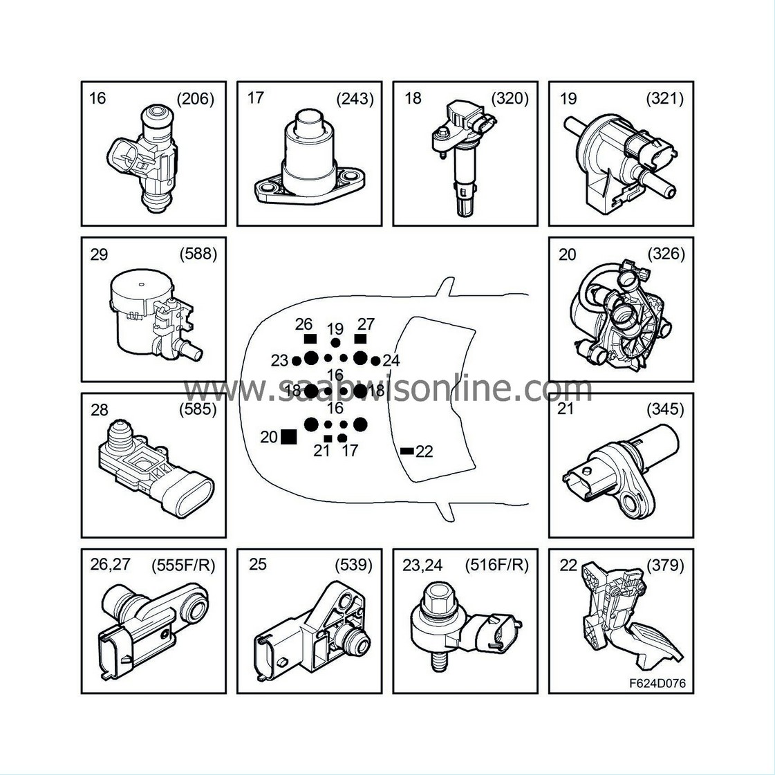
Injectors (206a-f)

|
|
| 17. |
Level sensor, engine oil (243)
|
|
| 18. |
Ignition coil with integrated power amplifier (320a-f)
|
|
| 19. |
Solenoid valve, EVAP canister purge (321)
|
|
| 20. |
Motor, secondary air injection pump (326)
|
|
| 21. |
Crankshaft position sensor (345)
|
|
| 22. |
Accelerator pedal position sensor (379)
|
|
| 23. |
Knock sensor, front cylinder bank (516F)
|
|
| 24. |
Knock sensor, rear cylinder bank (516R)
|
|
| 25. |
Atmospheric pressure sensor (539)
|
|
| 26. |
Position sensor, intake camshaft, front cylinder bank (555F)
|
|
| 27. |
Position sensor, intake camshaft, rear cylinder bank (555R)
|
|
| 28. |
Manifold absolute pressure sensor (585)
|
|
| 29. |
Solenoid valve, shut-off EVAP (588)
|
|
| 30. |
Preheated oxygen sensor, front (592)

|
|
| 31. |
Preheated oxygen sensor, rear (593)
|
|
| 32. |
Throttle body actuator unit (604)
|
|
| 33. |
Solenoid valve, turbo by-pass (605)
|
|
| 34. |
Control module, Motronic E9, V6 petrol (608)
|
|
| 35. |
A/C pressure sensor (620)
|
|
| 36. |
Fuel pressure sensor, fuel rail (653)
|
|
| 37. |
Intake air sensor (688) contains:
|
|
| • |
Intake air temperature sensor (407)
|
| • |
Charge air pressure sensor (603)
|
| 38. |
Fuel pump unit (689) contains:
|
|
| • |
Level sensor, fuel (46)
|
| • |
Engine, fuel pump (323)
|
| 39. |
Solenoid valve, intake camshaft, front cylinder bank (695F)
|
|
| 40. |
Solenoid valve, intake camshaft, rear cylinder bank (695R)
|
|
| 41. |
Engine oil pressure sensor (696)
|
|
| 42. |
Control module, fuel pump (697)
|
|
| 43. |
Relay unit, radiator fans (706a)
|
|
| 44. |
Column Integration Module (703, contains 141)
|
|
| General |

The Bosch ME 9.6 engine management system is used on all engine variants, but with different software content. The main task of the ECM is to regulate torque (air mass), fuel and ignition. the control module is screwed to the plenum chamber and is connected via two 64-pin connectors - one to the car harness and one to the engine harness.
The software in ECM can be updated via SPS.
| Engine torque |

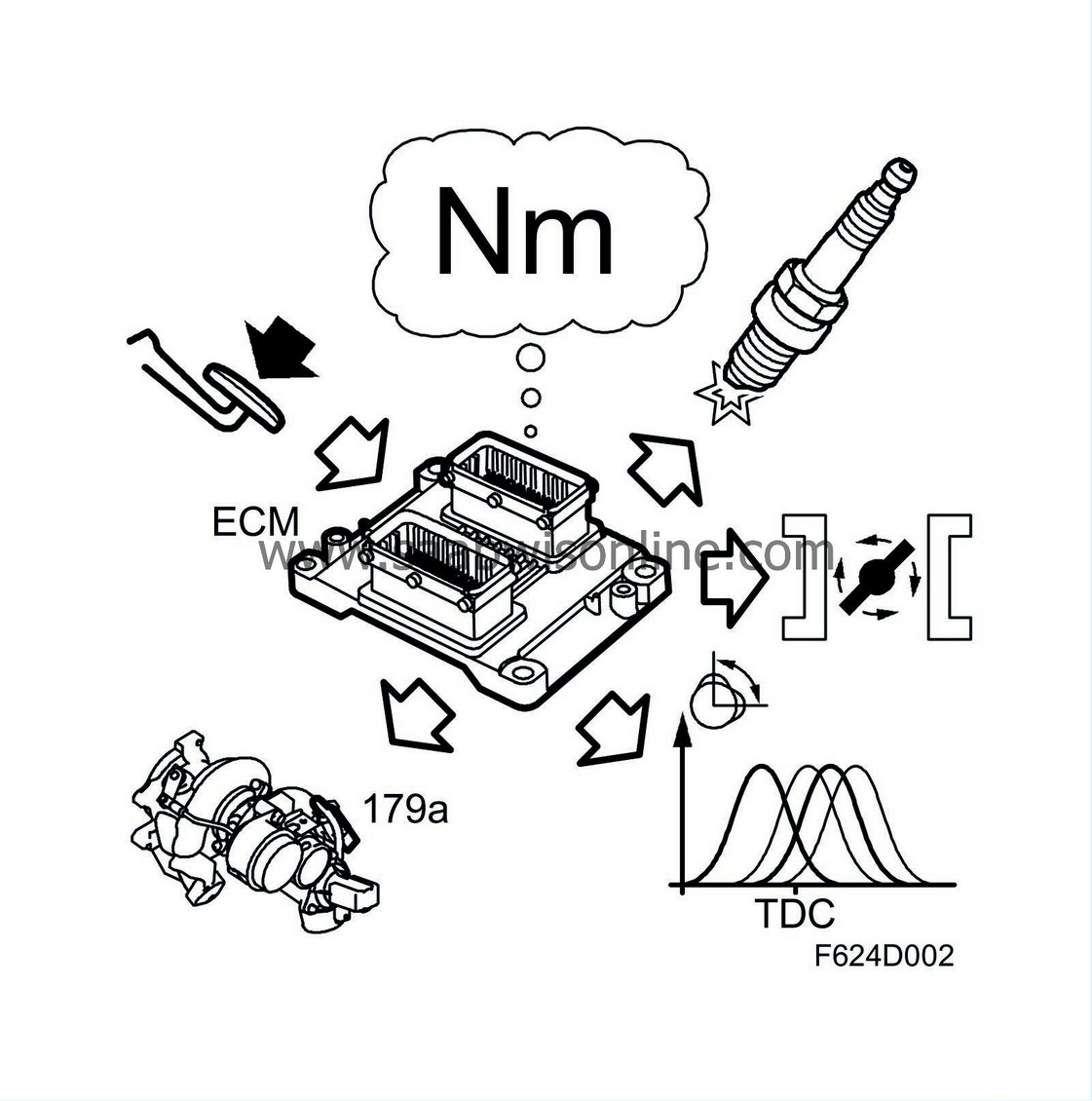
ECM ensures that the correct engine torque is achieved during any driving condition. It does so by combining all external torque requests (accelerator pedal, cruise control and TCS/ESP) with the internal ones. The internal torque requests (e.g. idle control) can be positive or negative (limiting). Some examples of limitations are maximum permissible torque or maximum permissible vehicle speed. When the external and internal torque requests are compiled, a result is calculated, i.e. requested engine torque in Nm. This is then converted to necessary (requested) air mass per combustion (mg/c) for the actual point of operation.
The requested air mass is converted to:
| • |
Throttle area request
|
|
| • |
Turbo request
|
|
| • |
Camshaft position
|
|
| Ignition |

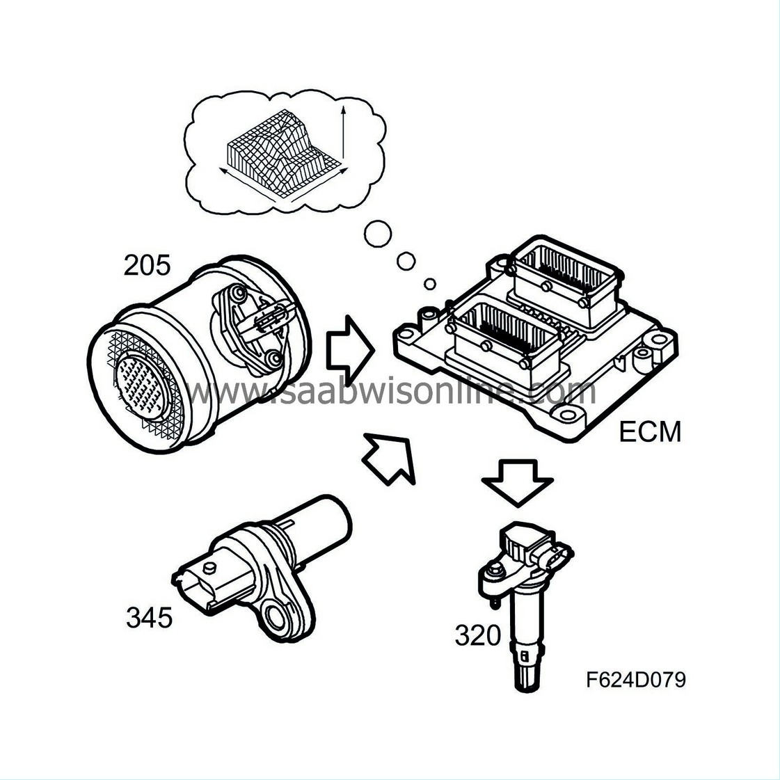
ECM uses the actual air mass per combustion and engine speed to calculated ignition timing. Ignition timing is retrieved from a matrix in which air mass per combustion and engine speed indicate a specific value. This value then undergoes a number of corrections based on operating conditions, e.g. coolant temperature and charge air temperature. The ignition coils are regulated based on the corrected value for camshaft angle and ignition timing. The value is calculated for each combustion to optimise function. The ignition coils have an integrated power amplifier.
Knock control

Combustion in a petrol engine can be of a good nature (normal combustion) or a bad nature (knocking). Knocking can be very damaging to the engine and must therefore be monitored. The engine is equipped with one piezoelectric knock sensor per cylinder bank. The sensor is mounted on the cylinder bank and can be equated to a microphone that listens to engine noise. Knocking generates characteristic noises that are caught by the sensors, which are connected to ECM.
Knock control is individual to each cylinder. This means that, for example, the ignition timing of a knocking cylinder can be temporarily retarded which the other cylinder retain their normal ignition timing. If ignition retardation does not stop the knocking, engine torque is reduced to prevent engine damage.
Note that it is completely normal to hear single knocks even though there is no fault. If the engine continually knocks loudly, however, there is a fault.
| Continous variable cam phasing (CVCP) |

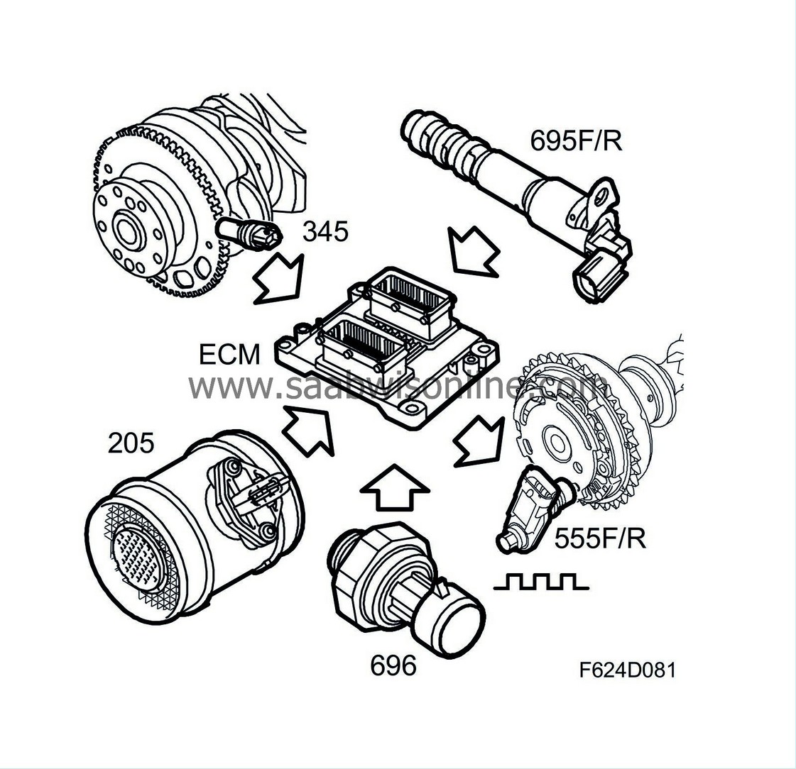
Continous variable cam phasing (CVCP) is a system that makes continual variation of the intake camshafts' position, i.e. phasing, possible. The duration (the number of degrees the values are hold open) remains constant. It is the position of the cam lobes, i.e. the camshaft angles when the intake values open or close, that are different. This is controlled by ECM via hydraulic valves in order to obtain the optimal intake camshaft setting at any given operating point.
Since ECM regulates the hydraulic valves with a PWM voltage, the valves can be stepplessly moved into the requested postion. To compensate for the oil delivery pressure, the engine is equipped with a pressure sensor that measures engine lubricating oil pressure.
CVCP has the following advantages:
| • |
High engine output
|
|
| • |
High engine torque over a broad rpm range
|
|
| • |
Reduced emissions, especially NOx
|
|
| • |
Reduced fuel consumption
|
|
| Components |
Control module, ME9 (608)
ECM reads the driver's required power output (torque request) and with the help of several sensors, it calculates the permissible amount of fuel to use in mg/combustion.Its internal diagnosis can be read directly using the diagnostic tool.
ECM also reads the digital information from the cruise control system switch and, if required by the driver, the engine control module will control the speed of the car.
The radiator fan speed is controlled by ECM.
Generator (2)
ECM controls the charge from the generator and compensates for its torque load.When ECM has registered that the engine has started by calculating the engine speed signal, charging will start.
Brake light switch (29)
The switch informs ECM of the brake pedal position. It is used to turn off cruise control.Relay, fuel pump (102)
The relay is activated by ECM when it is time to start the fuel pump.Clutch switch, cruise control (133)
The switch informs ECM of the clutch pedal position. It is used to turn off cruise control.Brake switch, cruise control (134)
The switch is used to carry out a feasibility assessment of the brake light switch. It is also used to turn off the cruise control.Relay, A/C compressor (156)
The relay controls engagement and disengagement of the A/C compressor after a command from ECM. Meanwhile, ECM will compensate for the increase/decrease in engine torque requirements.Boost pressure control valve (179a)
A PWM regulated solenoid valve that controls air pressure to the turbocharger wastegate box and thereby boost pressure.Temperature sensor, coolant, engine management system (202)
The temperature sensor measures the engine temperature. ECM uses the reading to deliver more fuel to the engine when the engine is cold. In addition, it can protect the engine against harmful overheating because the control module will limit the amount of fuel if there is a risk of overheating. The speed of the radiator fans is controlled by the engine temperature.Mass air flow sensor (205)
Measures air mass coming in to the engine in grams per second. This value is used to calculate required fuel, engine torque and ignition timing.Injectors (206a-f)
Each cylinder has a high-ohm, dual jet injector that delivers a fine mist of fuel to the intake valves.Main relay, engine management system (229)
The relay controls the power supply to most of the engine management system components.Level sensor, engine oil (243)
A float sensor whose tongue-element switch opens when the oil level becomes too low.Ignition coil with integrated power amplifier (320a-f)
Each spark plug has an inductive ignition coil with integrated power amplifier.Solenoid valve, EVAP canister purge (321)
The purge valve controls the quantity of air/fuel drawn into the engine for the current operating conditions.Relay, secondary air injection pump (324)
The relay regulates activation of the secondary air injection pump.Motor, secondary air injection pump (326)
Crankshaft position sensor (345)
An inductive sensor transmits alternating current with a frequency proportional to engine speed. ECM uses each pulse to determine when the engine is in top dead centre.Accelerator pedal position sensor (379)
The position sensor contains two potentiometers that inform ECM on the driver's torque request. Potentiometer 1 gauges the position of the accelerator pedal, which potentiometer 2 is used to diagnose potentiometer 1.Knock sensor, front cylinder bank (516F)
A piezoelectric accelerometer that measures engine noise, especially the characteristic engine noise that occurs during knocking.Knock sensor, rear cylinder bank (516R)
A piezoelectric accelerometer that measures engine noise, especially the characteristic engine noise that occurs during knocking.Relay, +50 (517)
When ECM has checked that all the starting conditions have been met, it will activate the relay so that the starter motor cranks.Atmospheric pressure sensor (539)
Measures existing atmospheric pressure.Position sensor, intake camshaft, front cylinder bank (555F)
Hall sensor that gauges the position of the intake camshafts. Also used to synchronise the engine.Position sensor, intake camshaft, rear cylinder bank (555R)
Hall sensor that gauges the position of the intake camshaft.Manifold absolute pressure sensor (585)
The pressure sensor values are used to detect leaks in the EVAP system.Solenoid valve, shut-off EVAP (588)
Shut-off valve used during diagnosis to detect leaks in the EVAP system.Preheated oxygen sensor, front (592)
Wideband oxygen sensor with pumped O2 reference that measures the current lambda value in the exhaust flow.Preheated oxygen sensor, rear (593)
Narrow band oxygen sensor whose values are used to diagnoses the front catalytic converter.Throttle body actuator unit (604)
Throttle body with spherical neck. The throttle is maneuvered by a DC motor and two potentiometers. Potentiometer 1 measures the throttle disc position and potentiometer 2 is used to diagnose potentiometer 1.Solenoid valve, turbo by-pass (605)
A PWM-regulated solenoid actuates a valve cone, which in turn prevents the compresor from passing the pump limit when the throttle valve closes.A/C pressure sensor (620)
Measures the prevailing pressure in the high pressure side of the A/C system.Used for load compensation, cooling fan function and sent as a bus message for use by the ACC.
Fuel pressure sensor, fuel rail (653)
The fuel rail pressure is measured by the pressure sensor so that ECM can regulate the pressure in the fuel rail and thereby the amount of fuel to the injector.Intake air sensor (688)
The combined pressure and temperature sensor measures the temperature and pressure of the intake air.The pressure sensor (607) measures the pressure in the intake manifold so that ECM can control turbocharger boost pressure.
The temperature sensor (403) measures the temperature of intake air so that ECM can request the correct air mass for combustion (hot air requires a high volume).
Fuel pump unit (689)
The fuel pump unit contains the fuel level sensor (46) and the fuel pump (323).The level sensor measures the amount of fuel in the tank.
The fuel pump works at low pressure and delivers fuel to the high-pressure pump.
Solenoid valve, intake camshaft, front cylinder bank (695F)
A PWM-regulated solenoid actuates a valve plunger, which in turn directs the oil to the CVCP mechanism.Solenoid valve, intake camshaft, rear cylinder bank (695R)
A PWM-regulated solenoid actuates a valve plunger, which in turn directs the oil to the CVCP mechanism.Engine oil pressure sensor (696)
The value is used to warn of low oil pressure and to compensate PWM control of the solenoid valves for CVCP.Control module, fuel pump (697)
Gauges the fuel pump via a PWM signal in order to regulate fuel pressure.CIM (703)
If the transponder code is approved, a signal is sent to the ISM to allow the key to turn. Once this has been done, the engine can be started.With help of the integrated cruise control switch (141) the driver can request that ECM should maintain vehicle speed alternatively reduce or increase the set vehicle speed.


