Connector, handling and checks
|
|
Connector, handling and checks
|
|
1.
|
It is important when removing captive connectors to release the lock before removing the connector. Make sure the connector locks properly when connecting.
Before removing a connector you must ensure that no fluid, dirt or the like can enter the connector.
Examples of different types of connectors on some cars:
|
|
|
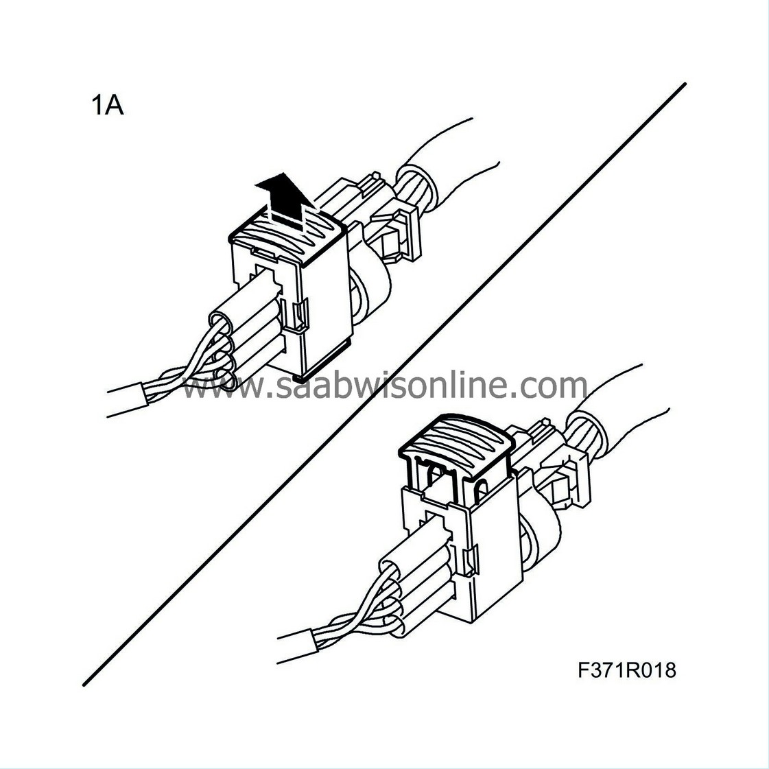
1.A.
|
Pull out the slide to release the connector's lock.
After connection the connector is locked by pushing in the slide.
|
Note
|
|
Use a small screwdriver to make it easier to loosen the lock on the connector.
|
|
|
|
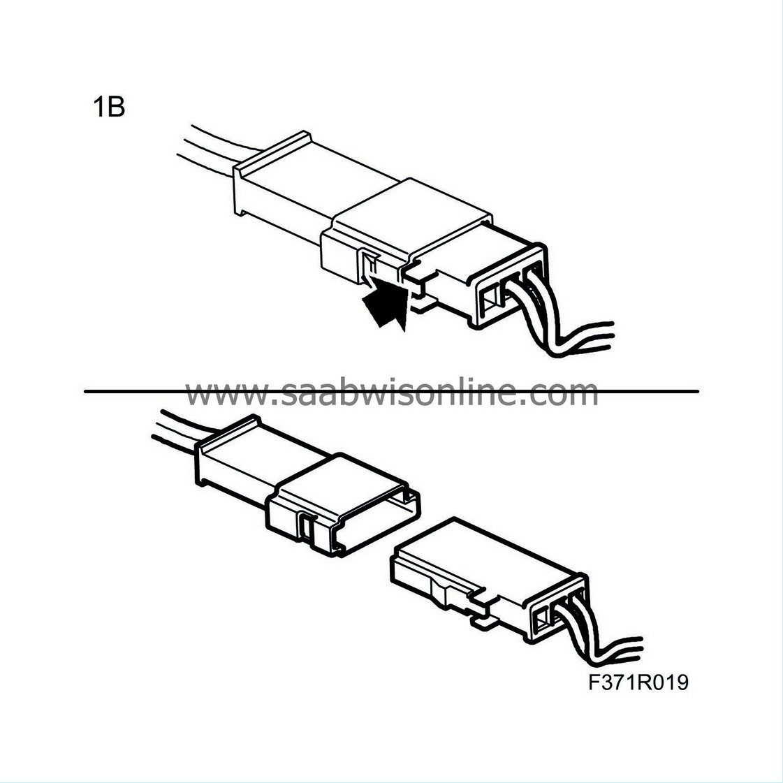
1.B.
|
Push in the locking tab to release the connector's lock.
Make sure the connector is locked properly when connecting.
|
|
|
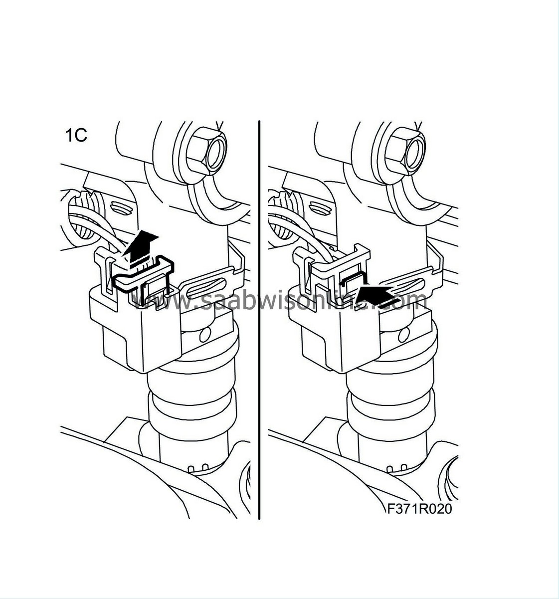
1.C.
|
Pull out the slide to release the connector's lock.
After connection the connector is locked by pushing in the slide.
|
|
|
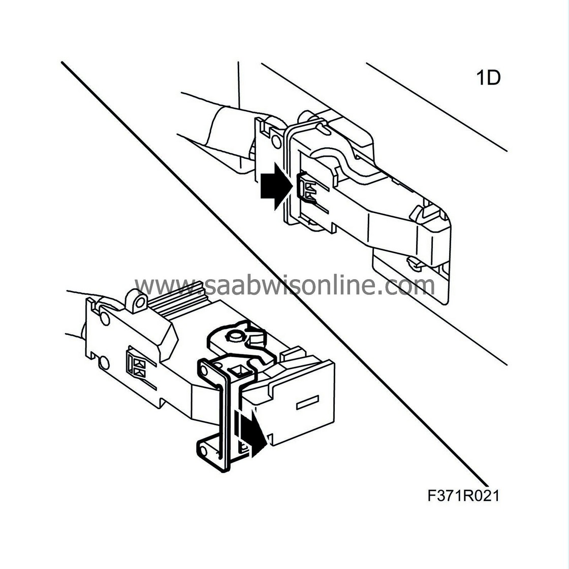
1.D.
|
Push in the clamp's locking catch and fold the clamp forward.
When connecting, fold back the clamp to lock the connector.
|
Note
|
|
Make sure that the clamp is locked in the right position to guarantee contact between the connectors.
|
|
|
|
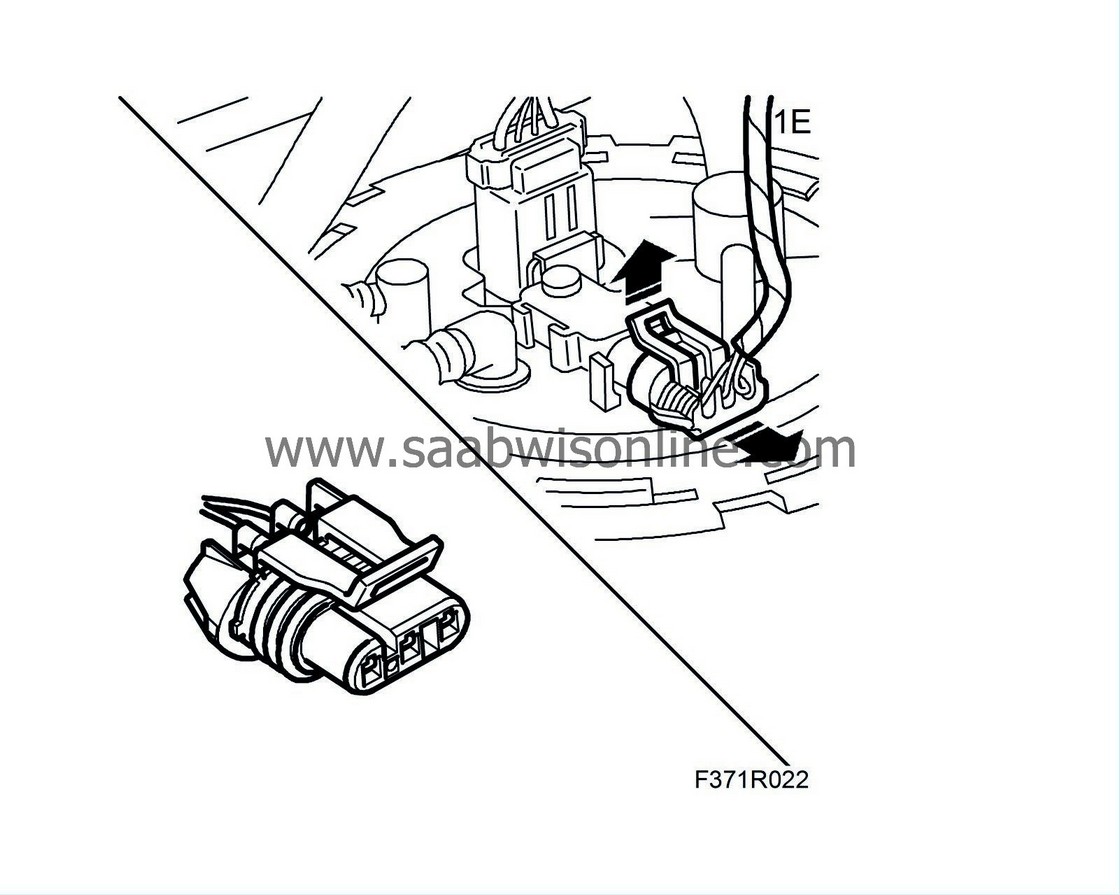
1.E.
|
Lift up the locking tab to release the connector's lock.
Make sure the connector is locked properly when connecting.
|
|
|
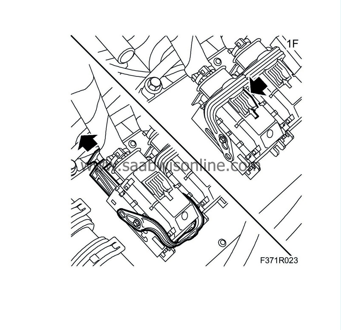
1.F.
|
Press in the connector's locking tab to release the clamp. Release the connector's slide and at the same time fold forward the clamp.
|
Note
|
|
The connector can be damaged if greater force than necessary is used to fold the clamp forward without releasing the slide.
|
When connecting, fold back the clamp to lock the connector.
|
|
2.
|
Ground yourself, by taking hold of the car's body/engine, when removing or fitting the connector on the car's control module.
|
|
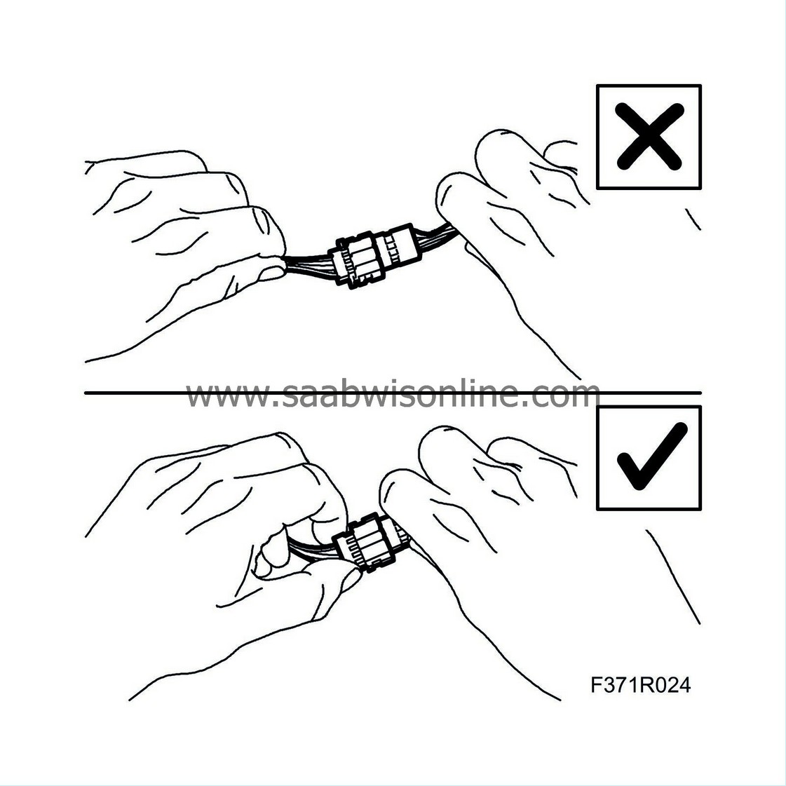
3.
|
Never pull the wiring harness when removing the connector.
|
|
4.
|
Never touch the pins on a control module with your hands or clothes.
|
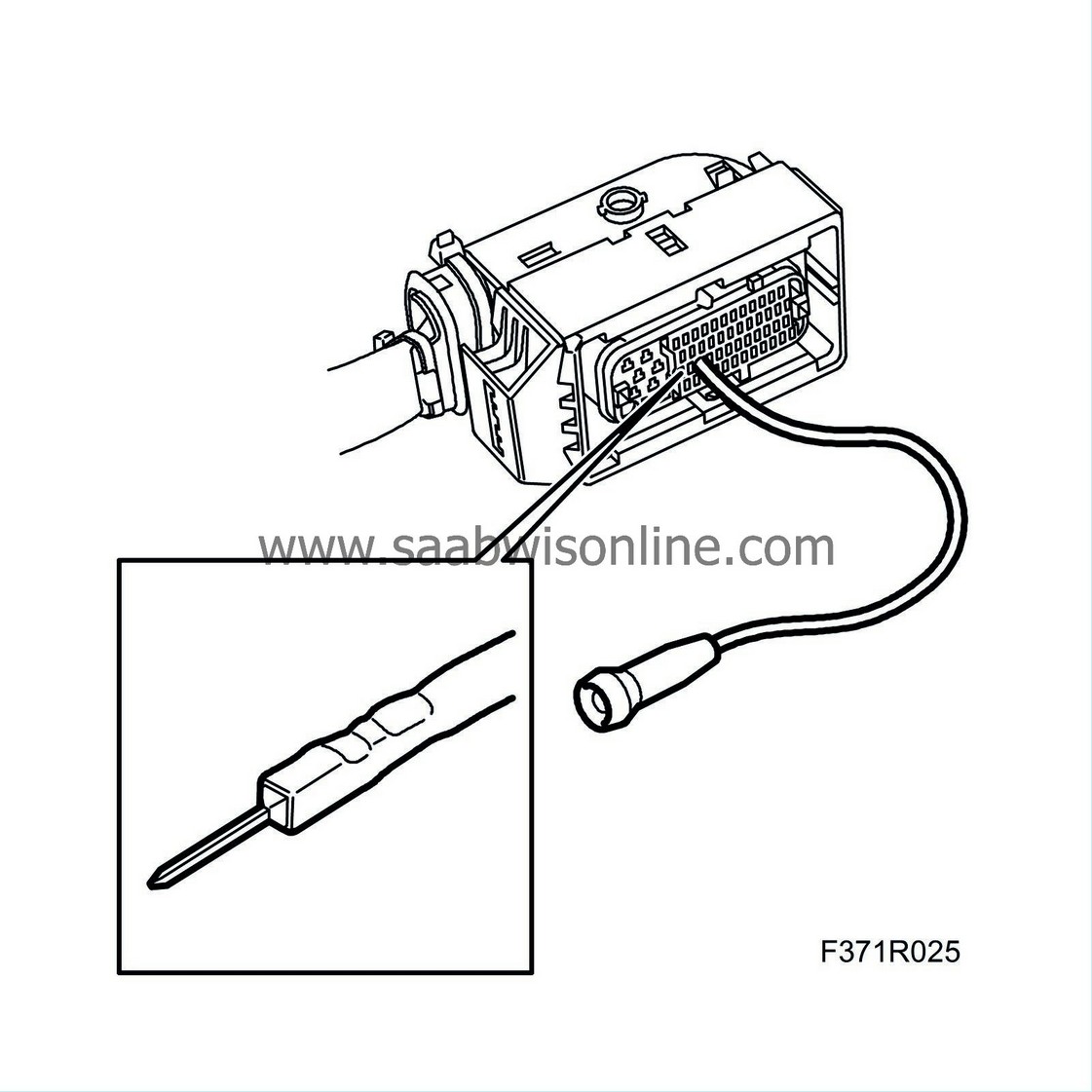
Important
|
|
Incorrect handing or the use of the wrong tool can damage the sleeves in the connector.
|
|
Use a test cable (part no. 86 12 731) of the correct size to avoid damaging the sleeves in the connector.
|
|
|
|
|
5.
|
When performing measurements, only use measurement probes designed for this purpose to avoid damage to the connectors. Use the right size test cable (part. no. 86 12 731).
|
|
6.
|
The connector may only be repaired using the specified special tools and spare parts.
|
|
7.
|
The following connectors must not be repaired:
|
|
|
•
|
Shielded cables/coaxial cable (e.g. ESP sensor cable)
|
|
|
•
|
Airbag system and pyrotechnic seat belt tensioner system
|
|
|
•
|
High voltage cable (e.g. ignition system, xenon lamp).
|
|
Note
|
|
Before fitting a connector you must ensure that no fluid, dirt or the like can enter the connector.
|
|
1.
|
Check that there are no contact problems on the connection.
|
|
2.
|
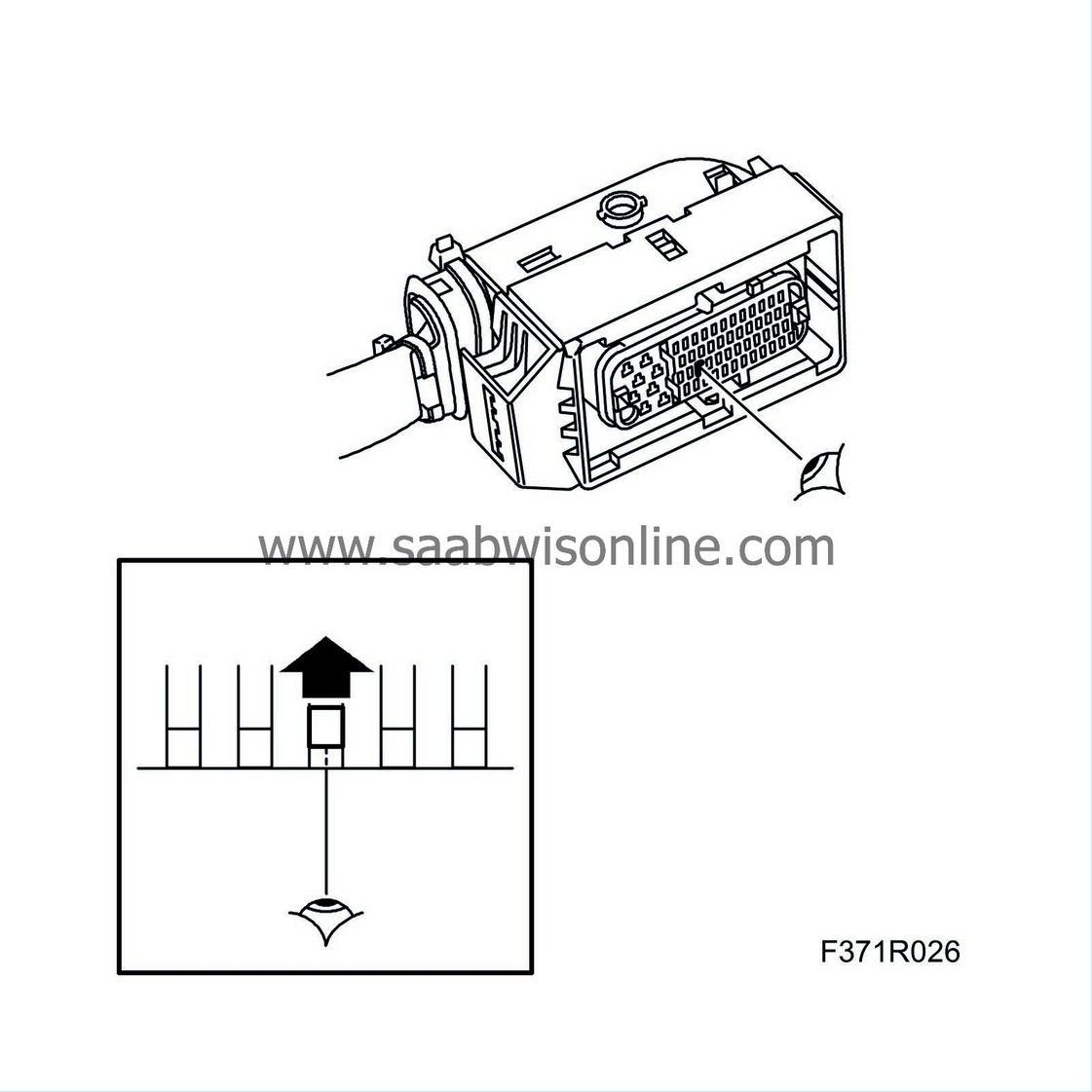
Check the connectors, splicing sleeves and crimps with regard to oxidation, dislodged pins and the pin's clamping force.
|
Important
|
|
Incorrect handing or the use of the wrong tool can damage the sleeves in the connector.
|
|
Use a test cable (part no. 86 12 731) of the correct size to avoid damaging the sleeves in the connector.
|
|
|
|
|
3.
|
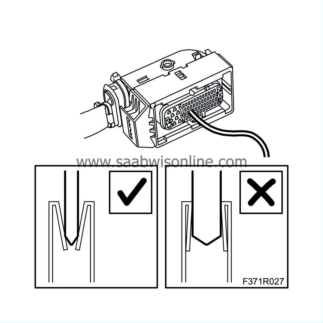
A test cable with the right pin size (from kit 86 12 731) must be used to check the connector's clamping force.
|
Note
|
|
A test cable that is too large will damage the connector's sleeves.
|
|
|
|
•
|
Insert the test cable's pins in the connector's pins to assess the clamping force on the relevant pins. Poor clamping force on the connector's pins can cause connector play.
|
|
|
•
|
Also check that the pins mate at the same height as the other pins in the connector. A too low mating height indicates pushed back pins in the connector, which can cause connector play.
|
|
4.
|
Check the cables or connectors to ensure there is no breakage.
|
|
5.
|
Check the wiring harness, splicing sleeves and earth connections.
|


