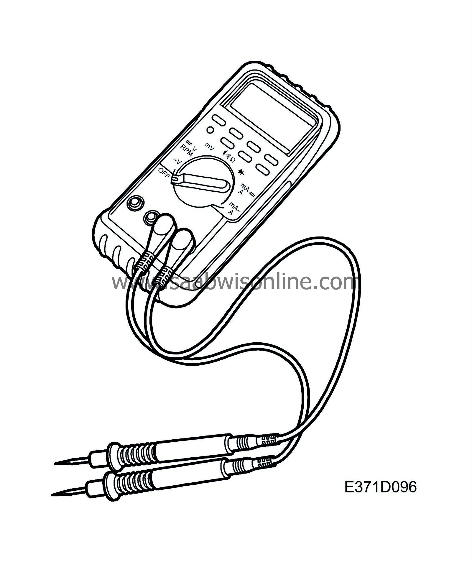
Testing for open/short circuits
| Testing for open/short circuits |
The ohmmeter must not be used to test components containing semi-conductors, e.g. control modules and relay with timing functions, etc.
When measuring resistance, the power supply to the system being tested must be disconnected as the measuring instrument generates a weak current in the circuit in question.
This is done to ensure that there is no current already in the tested circuit and that the correct reading is obtained.
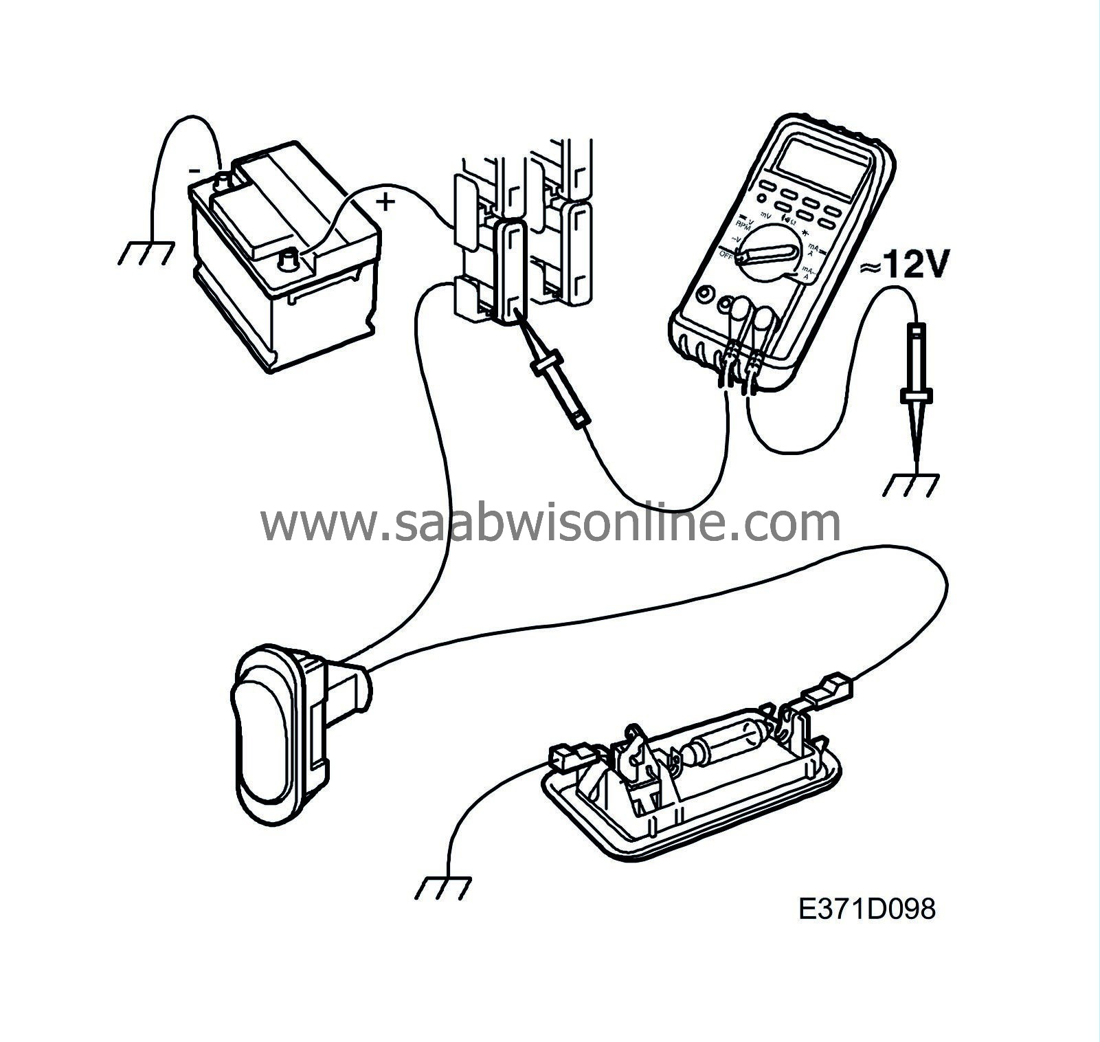
| Testing for open circuits by measuring voltage. |

| 1. |
Turn on the load.
|
|
| 2. |
Set the multimeter for measuring voltage and connect the negative lead of the voltmeter to a good grounding point.
|
|
| 3. |
Connect the positive lead of the voltmeter to the point where the voltage is to be read.
|
|
| 4. |
On the output side of switches/control modules, it is better to start checking from these and gradually work your way towards the load.
When there is no longer a voltage reading, you will have gone past the break point. |
|
| 5. |
On the input side of switches/control modules/consumers, it is better to start at the power source (normally a fuse) and then move gradually towards the switch/control module/consumer.
When there is no longer a voltage reading, you will have gone past the break point. |
|
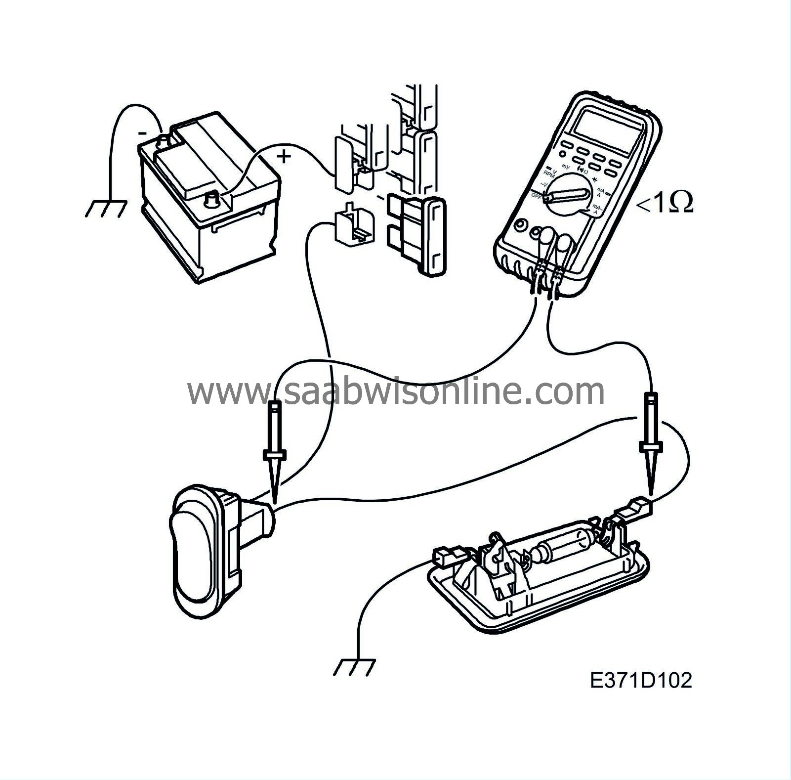
| Testing for open circuits by measuring resistance |

| 1. |
Make sure the component or lead to be tested is not under tension (e.g. by removing the relevant fuse).
|
|
| 2. |
Set the multimeter for measuring ohms and connect the ohmmeter to each end of the component/lead to be tested.
|
|
| 3. |
Jiggle the relevant wiring harness while observing the ohmmeter.
Normally, the resistance of a wiring harness is less than 1 ohm. Specified values apply to components. |
|
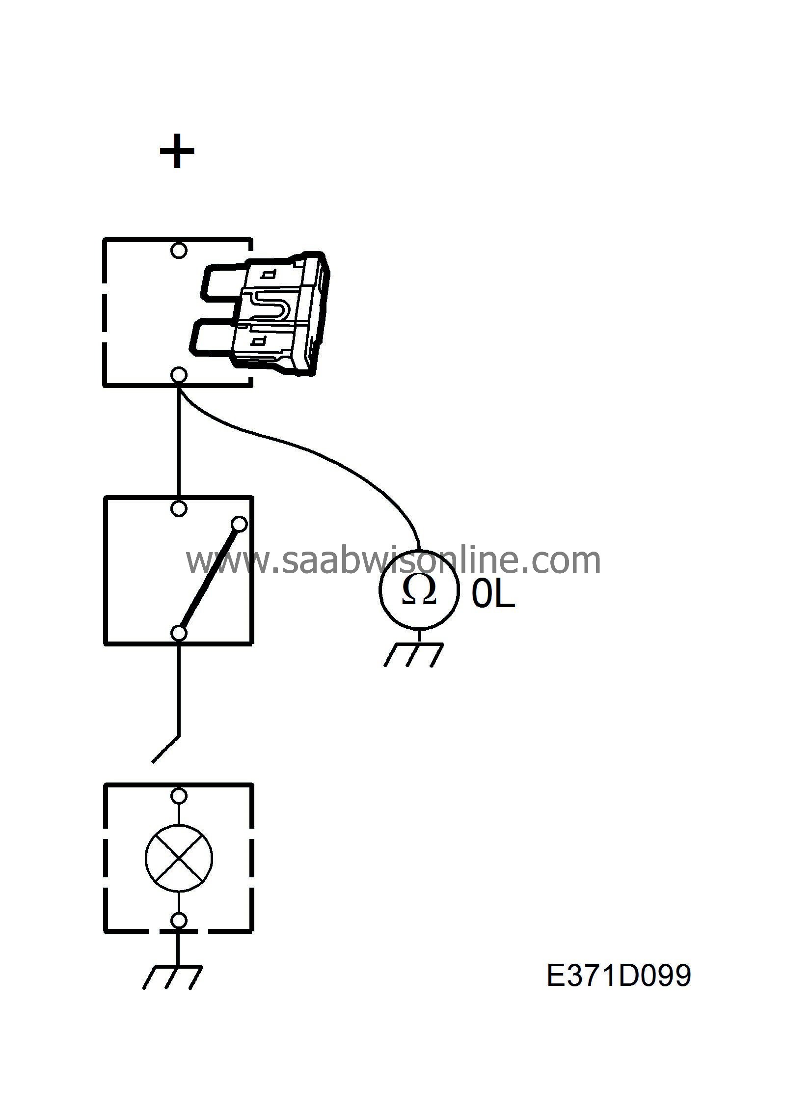
| Testing for short circuits to ground |
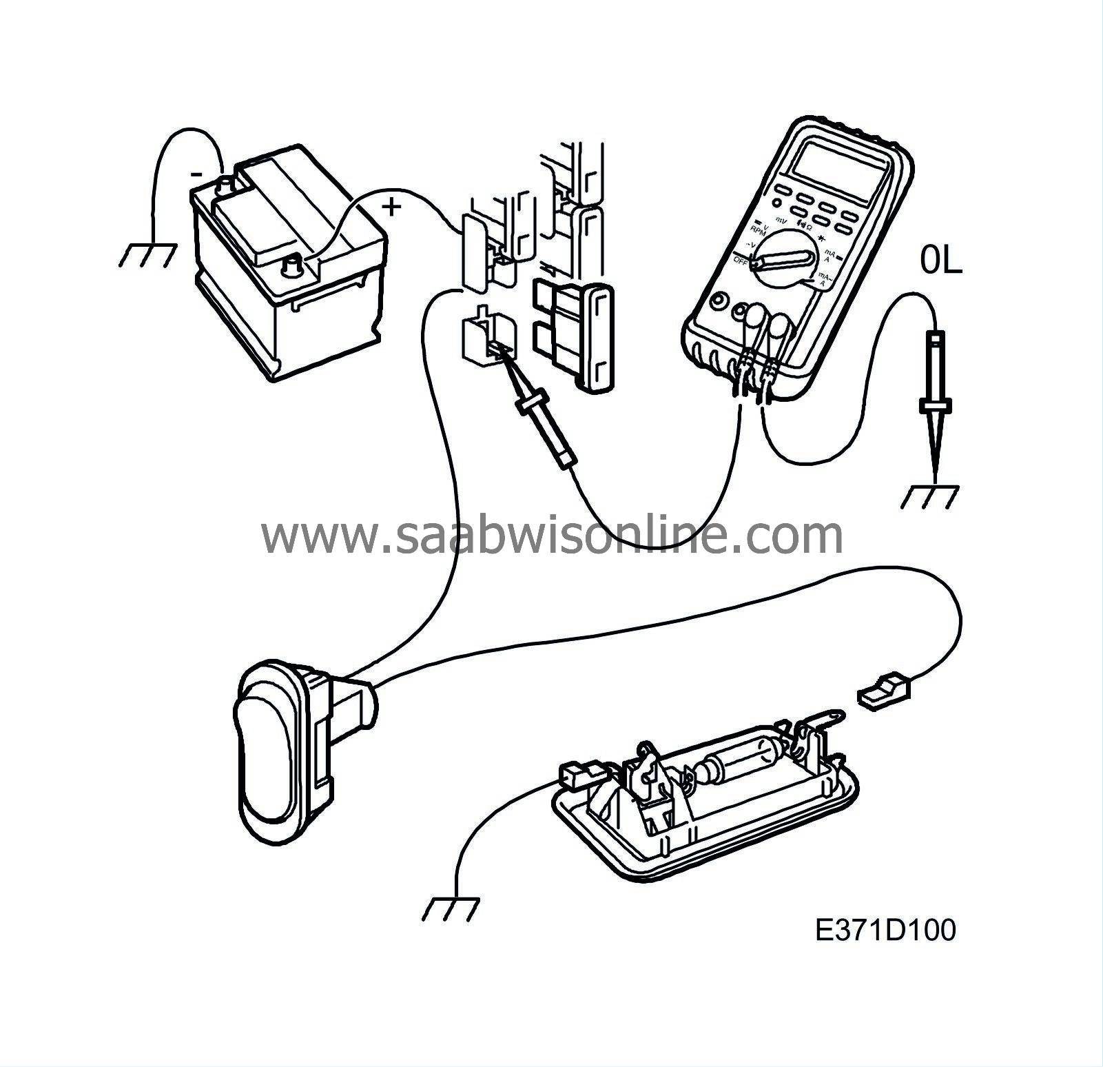
| 1. |
Make sure the lead being tested is not under tension (e.g. remove the relevant fuse) and that any loads are disconnected.
|
|
| 2. |
Set the multimeter for measuring ohms.
|
|
| 3. |
Connect one test lead to a good ground and the other to the point to be tested.
|
|
| 4. |
Carefully jiggle the wiring harness and make sure the multimeter reading shows infinite resistance (OL) all the time.
|
|

