Injector wiring harness, Z19 DTH
| Injector wiring harness, Z19 DTH |
| To remove |
| Important | ||
|
Take care when releasing the locking mechanism on the connector so as not to damage the connector. Pull the halves straight apart to avoid bending the pins. For further information regarding connectors, refer to Connectors, handling and inspection . |
||
| 1. |
Remove the battery cover.
|
|
| 2. |
Undo the cable for the battery's negative terminal.
|
|
| 3. |
Remove the upper engine cover and the sound insulation.
|
|
| 4. |
Raise the car.
|
|
| 5. |
Remove the spoiler shield (A). Unplug the connector (B) and remove the connector (C). Remove the lower engine cover (D).

|
|
| 6. |
Detach the lower wiring harness on the front of the engine.
|
|
| • |
Detach the purple connector housing of the engine control module (A).

|
| • |
Remove the clips (B).
|
| • |
Free the wiring so it hangs free.
|
| 7. |
Detach the AC compressor's connector housing (C).

|
|
| 8. |
Undo the hose clamps on the turbocharger induction pipe (D).
|
|
| 9. |
Detach the lower wiring harness on the rear of the engine.
Detach the following connector housings: |
|
| • |
Oil pressure sensor (44) (A)

|
| • |
Oil level sensor (243) (B)
|
| • |
Crankshaft position sensor (345) (C)
|
| • |
Free the wiring so it hangs free down in the engine bay.
|
| 10. |
Lower the car.
|
|
| 11. |
Remove the air pipe.
|
|
| • |
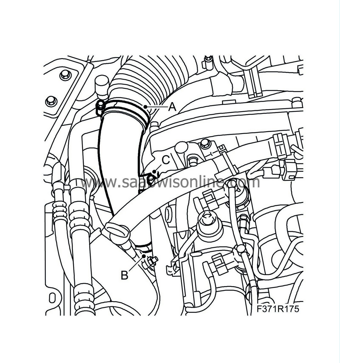
Detach the hose clamp (A)
|
| • |
Detach the hose clamp (B) for crankcase ventilation
|
| • |
Remove the screw (C) and lift out the pipe.
|
| 12. |
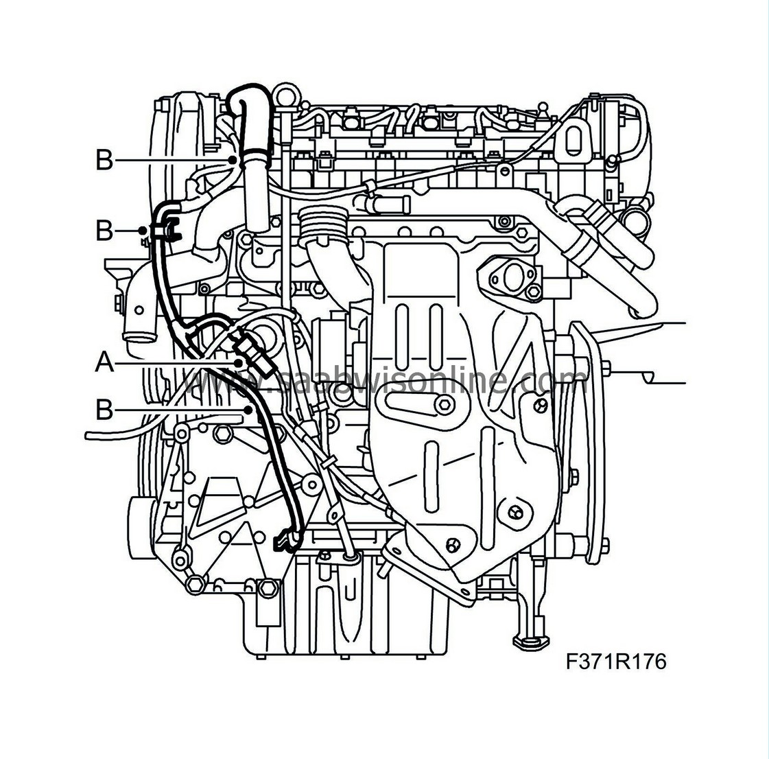
Detach the connector housing (A) of the exhaust temperature sensor (602).
|
|
| 13. |
Remove the fixings (B).
|
|
| 14. |
Detach the connector housing (A) of the mass air flow sensor (686).

|
|
| 15. |
Remove the 3 clips of the wiring harness (B).
|
|
| 16. |
Detach the engine harness' connector housing (A) and detach the connector housing (B) from the bracket.

|
|
| 17. |
Remove the clip (C).
|
|
| 18. |
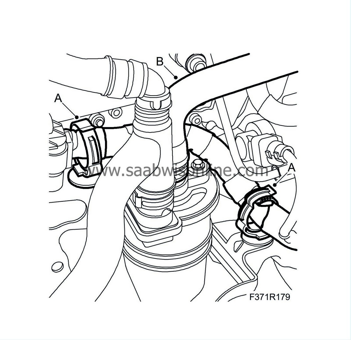
Remove the wiring harness clips (A).
|
|
| 19. |
Detach the pipe from the oil separator (B).
|
|
| 20. |
Detach the wiring harness on the upper rear of the engine.
Detach the following connector housings: |
|
| • |
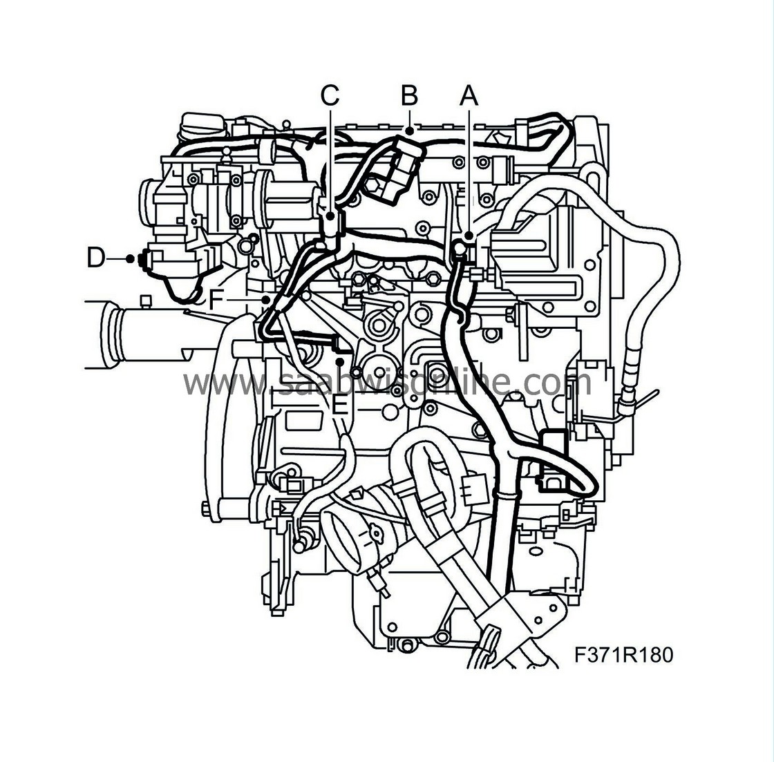
High pressure pump (652b) (A)
|
| • |
Intake air sensor (688) (B)
|
| • |
EGR valve (606) (C)
|
| • |
Throttle body (604) (D)
|
| • |
Combustion circulation (E)
|
| • |
Remove the fixing (F)
|
| 21. |
Use a small screwdriver to detach the temperature sensor's connector housing (A).

|
|
| 22. |
Remove the clip (B).
|
|
| 23. |
Detach the wiring harness on the top of the engine.
Detach the following connector housings: |
|
| • |
Fuel pressure sensor (653) (A)

|
| • |
Solenoid valve, fuel pressure (652a) (B) (some cars)
|
| • |
Glow plug (C)
|
| • |
Injectors (206) (D)
|
| • |
Camshaft position sensor (555) (E)
|
| • |
Undo the wiring harness fixings (F)
|
| • |
Remove the cable duct.
|
| 24. |
Remove the screws (A) of the crankcase ventilation pipe between the oil separator and the induction pipe.
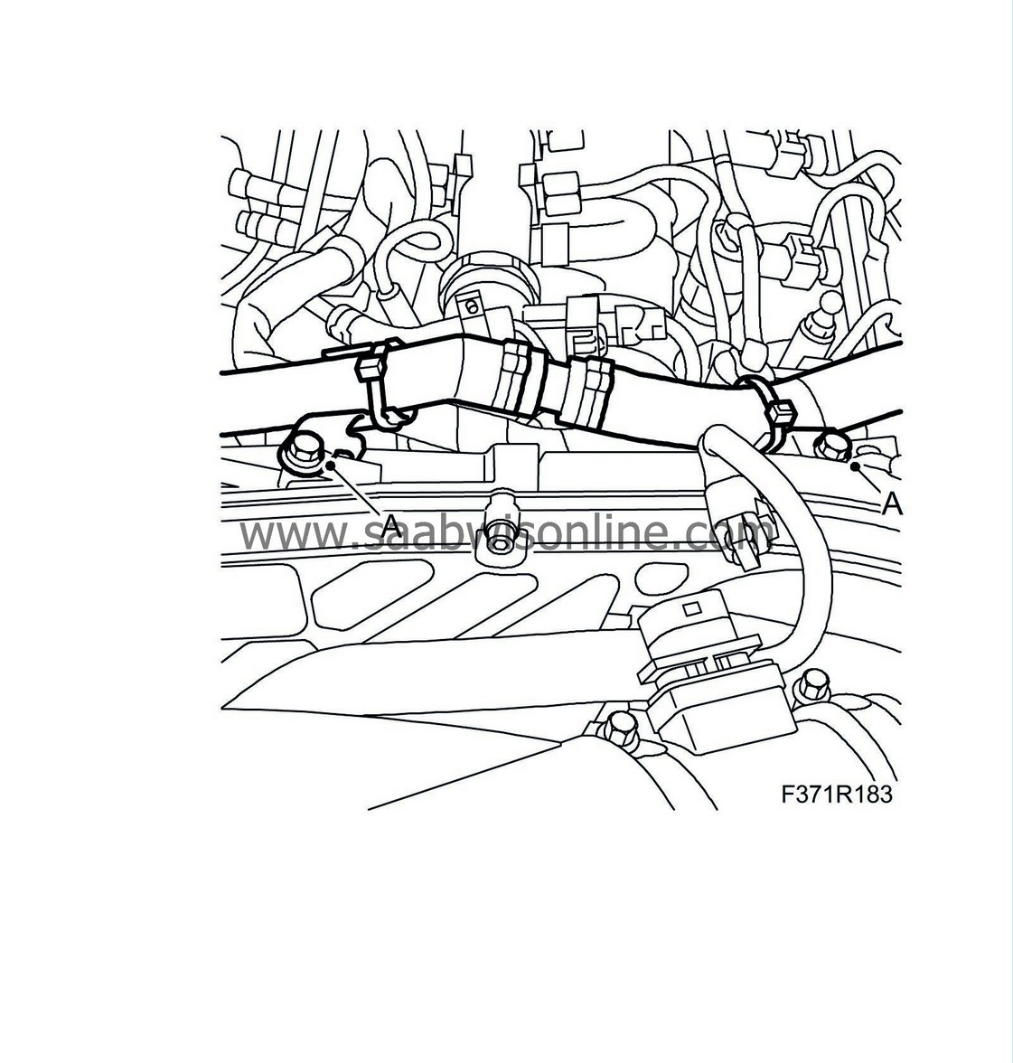
|
|
| 25. |
Lift away the wiring harness.
|
|
| To fit |
| Important | ||
|
Fasten the wiring harness correctly so that there is no risk of it chafing or rattling. |
||
| Note | ||
|
Spray all the connectors with “Kontakt 61” to prevent verdigris formation. Clean all the grounding points and coat them with Vaseline. |
| 1. |
Position the wiring harness on the engine.
|
|
| 2. |
Fit the screws (A) of the crankcase ventilation pipe between the oil separator and the induction pipe.

|
|
| 3. |
Fit the wiring harness on the top of the engine.
Attach the following connector housings: |
|
| • |
Fuel pressure sensor (653) (A)

|
| • |
Solenoid valve, fuel pressure (652a) (B) (some cars)
|
| • |
Glow plug (C)
|
| • |
Injectors (206) (D)
|
| • |
Camshaft position sensor (555) (E)
|
| • |
Engage the 3 clips of the wiring harness (F)
|
| 4. |
Attach the connector housing (A) of the exhaust temperature sensor (602).

|
|
| 5. |
Fit the clips (B).
|
|
| 6. |
Attach the wiring harness on the upper rear of the engine.
Attach the following connector housings: |
|
| • |
High pressure pump (652b) (A)

|
| • |
Intake air sensor (688) (B)
|
| • |
EGR valve (606) (C)
|
| • |
Throttle body (604) (D)
|
| • |
Combustion circulation (E)
|
| • |
Fit the fixing (F)
|
| 7. |
Fit the wiring harness clips (A).

|
|
| 8. |
Fit the pipe to the oil separator (B).
|
|
| 9. |
Attach the connector housing (B) to the bracket and attach the connector housing (A) of the engine harness.

|
|
| 10. |
Fit the 2 clips (C).
|
|
| 11. |
Attach the connector housing of the mass air flow sensor (A).

|
|
| 12. |
Fit the wiring harness clips (B).
|
|
| 13. |
Attach the connector housing (A) of the exhaust temperature sensor.

|
|
| 14. |
Fit the clips (B).
|
|
| 15. |
Attach the air pipe.
|
|
| • |
Position the pipe and fit the screw (C).

|
| • |
Fit the crankcase ventilation's hose clamp (B).
|
| • |
Fit the hose clamp (A).
|
| 16. |
Raise the car.
|
|
| 17. |
Attach the wiring harness on the lower rear of the engine.
Attach the following connector housings: |
|
| • |
Oil pressure sensor (44) (A)

|
| • |
Oil level sensor (243) (B)
|
| • |
Crankshaft position sensor (345) (C)
|
| 18. |
Attach the wiring harness on the lower front of the engine.
|
|
| • |
Attach the purple connector housing of the engine control module (A).

|
| • |
Fit the clips (B).
|
| 19. |
Attach the AC compressor's connector housing (C).

|
|
| 20. |
Fit the hose clamps on the turbocharger induction pipe (D).
|
|
| 21. |
Fit the lower engine cover (D), the connector (C) and plug in the connector (B). Fit the spoiler shield (A).

|
|
| 22. |
Lower the car.
|
|
| 23. |
Fit the upper engine cover and the sound insulation.
|
|
| 24. |
Attach the cable for the battery's negative terminal.
|
|
| 25. |
Fit the battery cover.
|
|
| 26. |
Carry out
Procedure after battery disconnection
.
|
|


