Switch unit, steering wheel (633)
| Switch unit, steering wheel (633) |
| Location |
Switch unit, steering wheel (633)
| Main use |
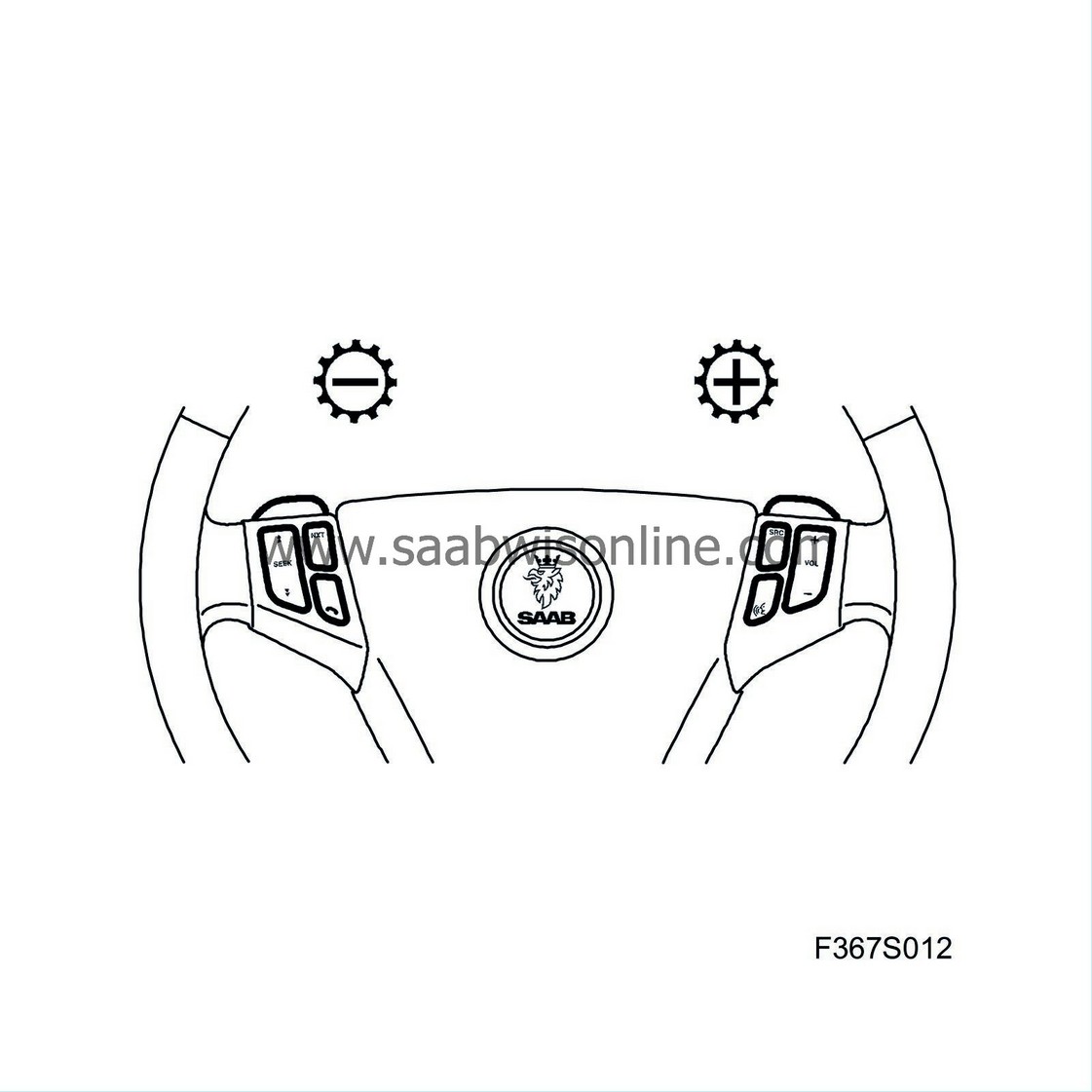
Operation of audio and telephone systems, changing up and down on automatic transmissions and horn switch.
| Type |
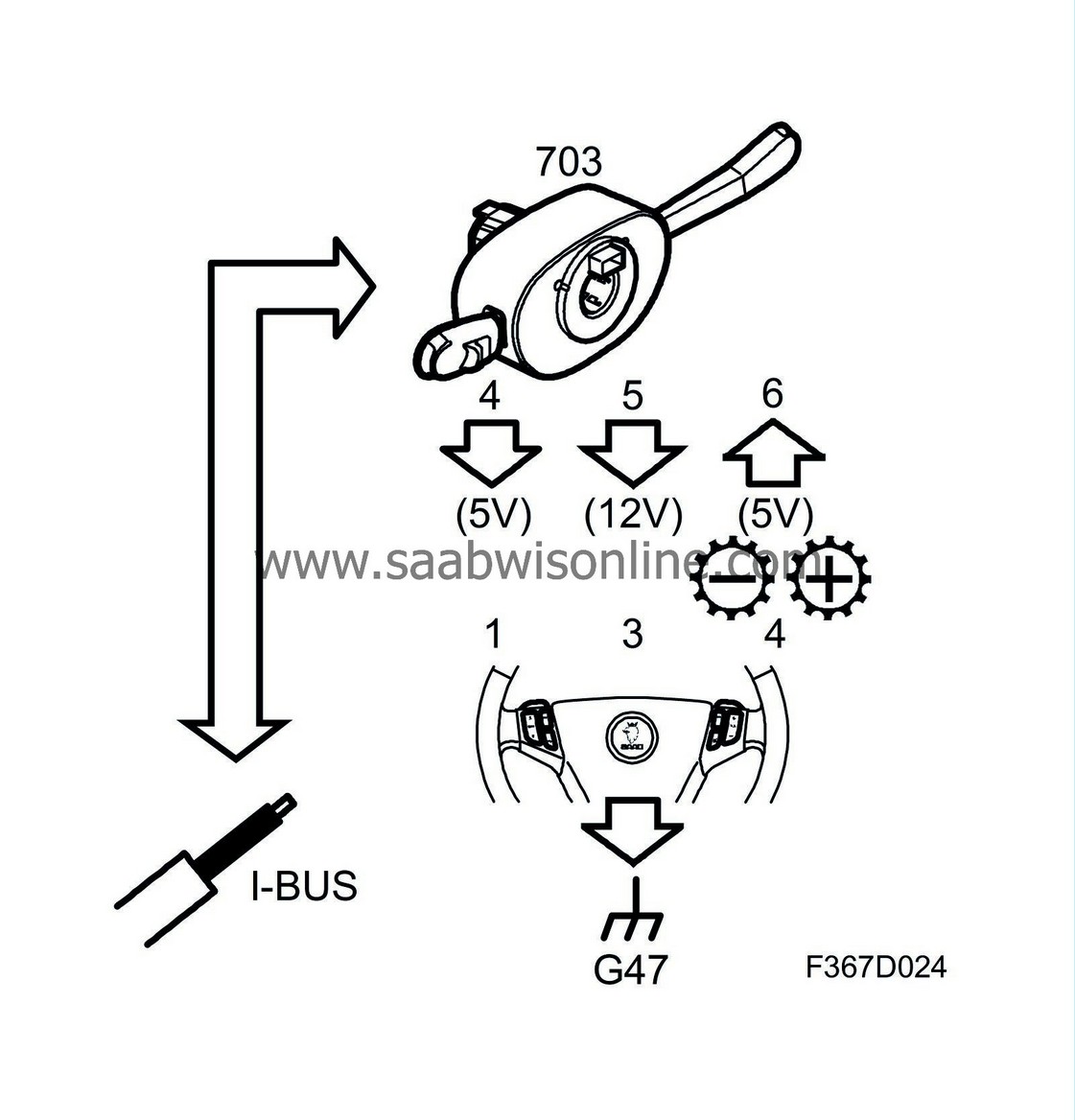
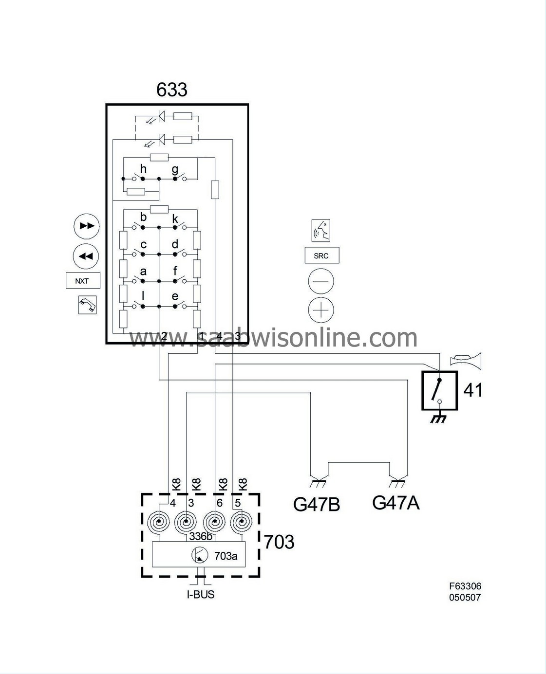
The steering wheel buttons are resistive multiplexed (5V) and divided into 2 circuits; Sentronic/horn in one circuit and other buttons in the second. The 2 circuits have a common ground from CIM. Each circuit has an extra resistor for diagnosing a break in the circuit.
The lead for the Sentronic/horn is fed with 5V via a 560Ω resistor integrated in CIM. When the horn switch closes, the line is grounded and the voltage drops to 0V. For changing up and down respectively there are 2 switches and 2 resistors: one for up and one for down changes. Depending on the switch being pressed, the total resistance will change and therefore also the voltage.
The buttons have integrated LEDs so that the symbols can be seen in the dark. The LEDs are powered by the CIM. All the leads go via a coil spring to CIM. CIM sends the status of the horn and the other buttons on the bus.

| Activation |
The CIM (column integration module) powers the button unit with 5 volts: for audio and telephone on pin 1 and for Sentronic/horn on pin 4. A common ground goes to pin 2. Depending on the switch being pressed, the total resistance will change and therefore also the voltage.
Pin 3 receives a 12 volt PWM signal to control the brightness of the LEDs.
| Pin no. | Interface | Description |
| 1 | 5V | Audio and telephone |
| 2 | Ground | Common ground, LEDs and buttons |
| 3 | 12V PWM | LEDs |
| 4 | 5V pull up | Sentronic/horn |

Wiring diagram, power supply


