Valve housing cover B284
| Valve housing cover B284 |
| To remove |
| 1. |
Position the wing cover. Engage gear position N and apply the parking brake.
|
|||||||||||||||
| 2. |
Undo the expansion tank cap and release any overpressure.
|
|
| 3. |
Raise the car.
|
|
| 4. |
Remove the front spoiler shield.
CV:
Remove
Chassis reinforcement, front subframe, CV
|
|
| 5. |
Position a receptacle under the car, connect a hose (A) and drain the cooling system.

|
|||||||||
| 6. |
Drain the transmission fluid.
|
|
| • |
Position a receptacle under the car.
|
| • |
Drain the transmission fluid via the drain plug (A). First remove the dipstick tube's plug (B) in order to access with an Allen key.
|
| • |
Fit the drain plug with a new seal. Fit also the level plug.
Tightening torque, drain plug 45 Nm (33 lbf ft) 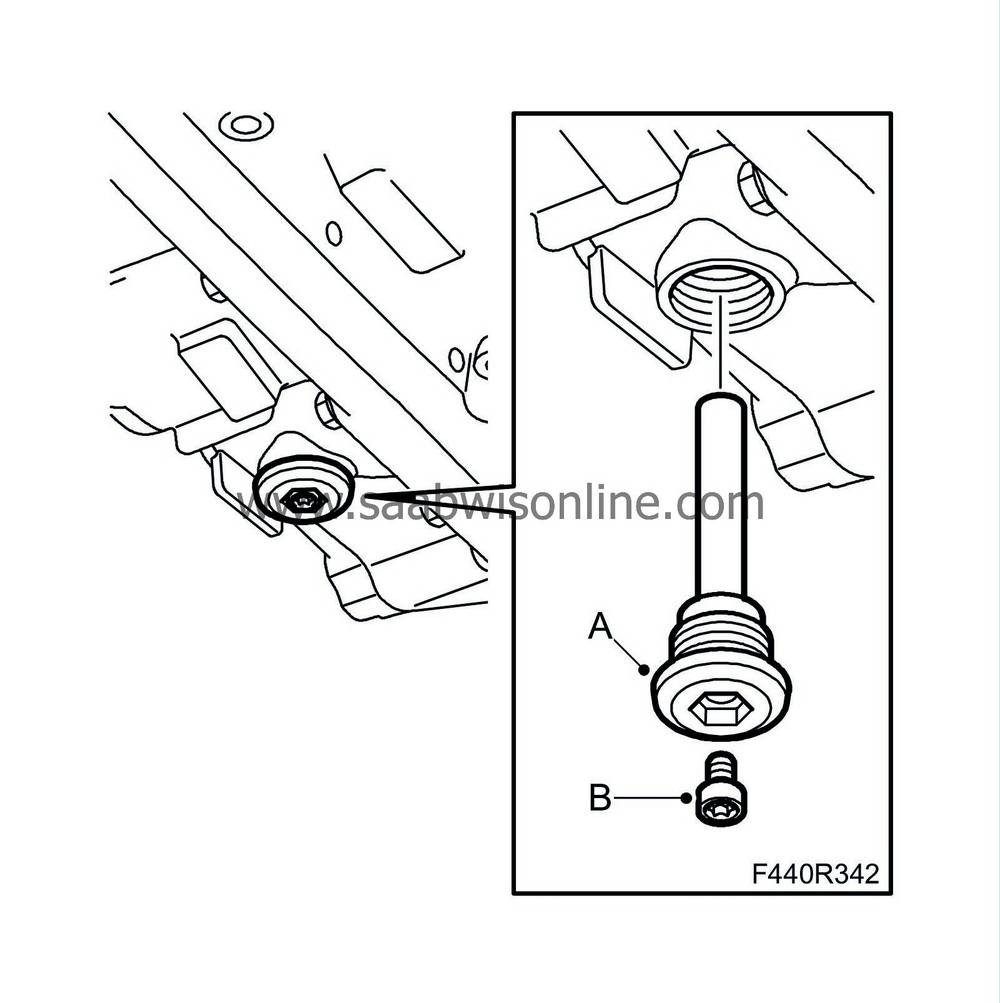
|
| 7. |
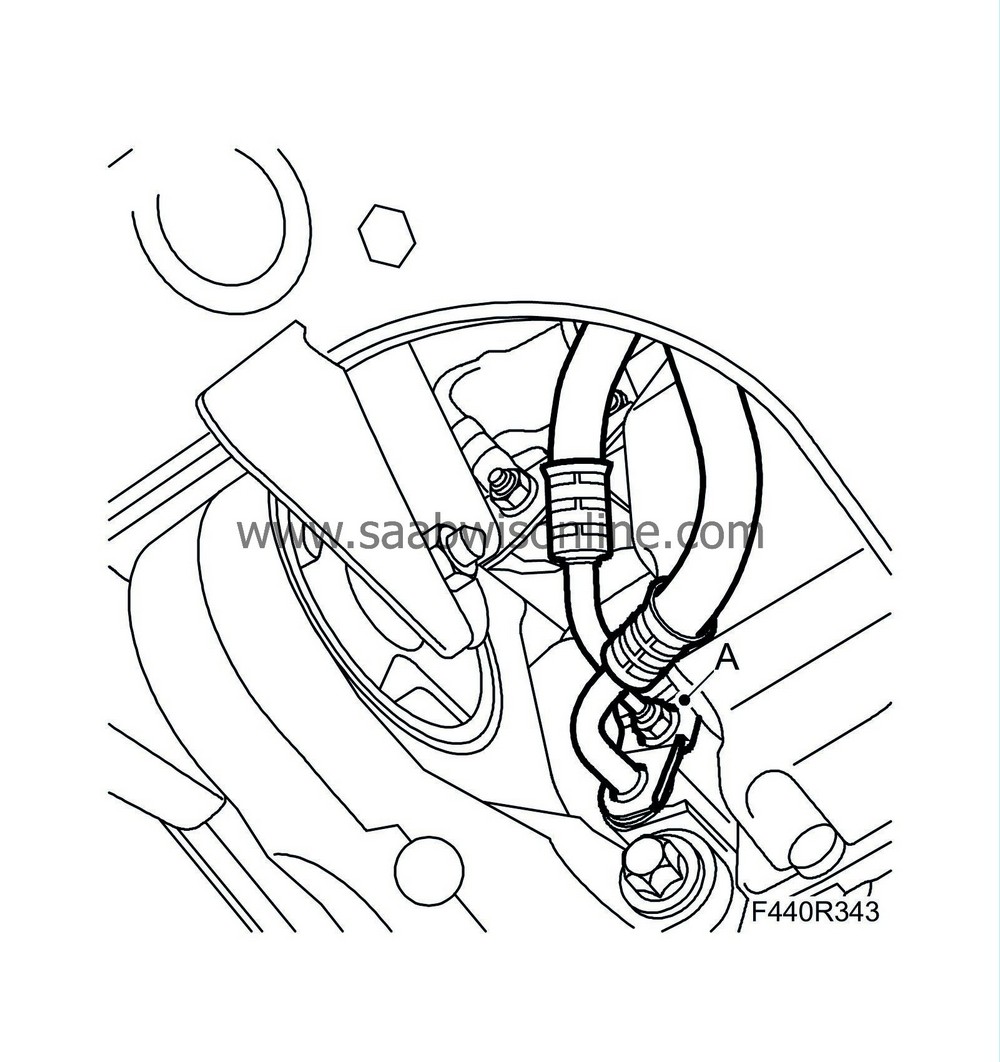
Remove the oil cooler hose connections from the gearbox. Plug the connections.
|
|
| 8. |
Remove the charge air pipe.
|
|
| • |
Remove the charge air pipe's lower hose connection and turn it to the side (A).
|
| • |
Remove the charge air pipe's lower retaining bolt (B).

|
| 9. |
Remove the lower cooler hose (C) from the cooler.
|
|
| 10. |
Lower the car to the floor.
|
|
| 11. |
Remove the
Battery
and
Battery cover, lower section, B284
|
|
| 12. |
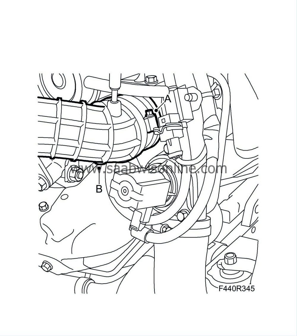
Remove and move aside the intake hose from the turbo.
|
|
| • |
Remove 1 x hose clip (A).
|
| • |
Move the hose (B) aside.
|
| 13. |
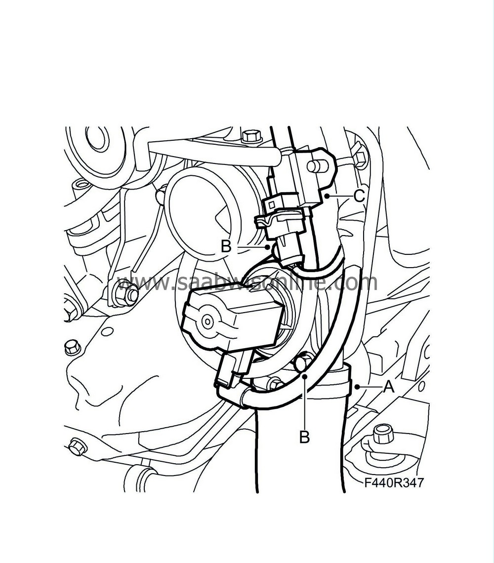
Remove the charge air pipe's hose from the turbo and lift away the pipe and the hose.
|
|
| • |
Remove 1 x hose clip (A)
|
| • |
Lift away the hose.
|
| 14. |
Remove the bypass valve from the turbo (C)
|
|
| • |
Remove 3 x screws (B).
|
| 15. |
Remove the solenoid valve (C) from the turbo, 1 x clip
|
|
| 16. |
Remove the cooler hose from the thermostat housing hose connection.

|
|
| • |
Remove 1 x hose clip (A).
|
| • |
Lift away the hose.
|
| 17. |
Disconnect the oil pipes from the cooler's connections.
|
|
| • |
Remove the dust cover for the upper pipe (A).
|
| • |
turn
87 92 806 Removal tool, oil pipe automatic transmission
slightly and detach the upper connection (A). At the same time, undo the pipe from the clip.

|
| 18. |
Remove the dust cover for the lower pipe (B) from the oil cooler. Use the removal tool for the oil pipe as above.
|
|
| 19. |
Remove the ground lead (A) and the clip (B) at the starter motor.
|
|
| • |
Remove 1 x nut.
|
| • |
Remove 1 x screw.

|
| 20. |
Remove the holder for the connectors and undo the wiring harness
|
|
| • |
Remove 1 x cable tie.
|
| • |
Remove 1 x clip. (A)
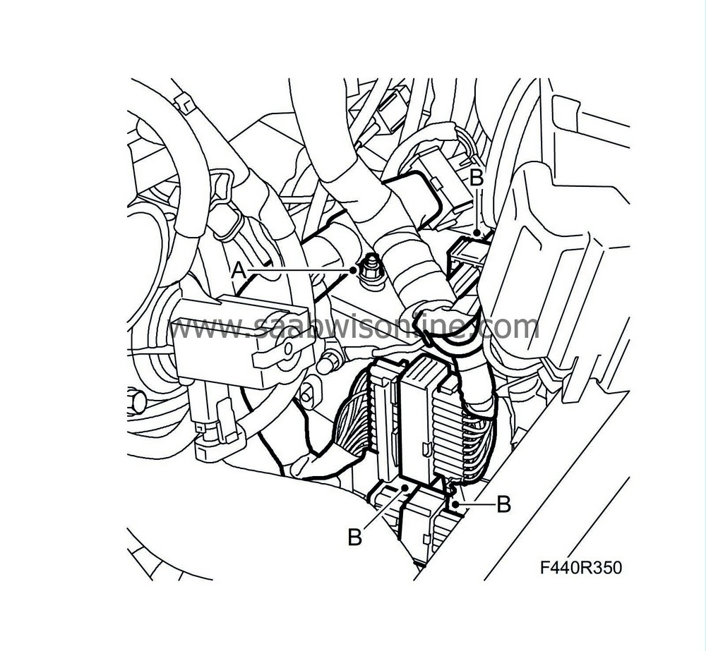
|
| • |
Unplug 3 x connectors. (B)
|
| • |
Remove 2 x nuts (C).
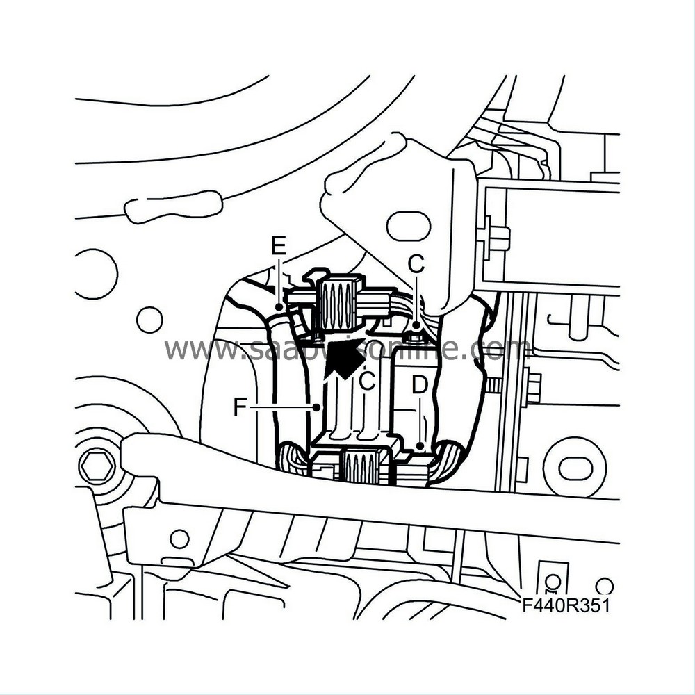
|
| • |
Unplug 1 x connector (D).
|
| • |
Remove 1 x mounting (F)
|
| • |
Remove 1 x cable tie (E)
|
| 21. |
Hold the wiring harness away with
83 95 212 Strap
|
|
| 22. |
Remove the valve housing cover.
|
|
| • |
Remove the two upper screws for the valve housing cover (A)
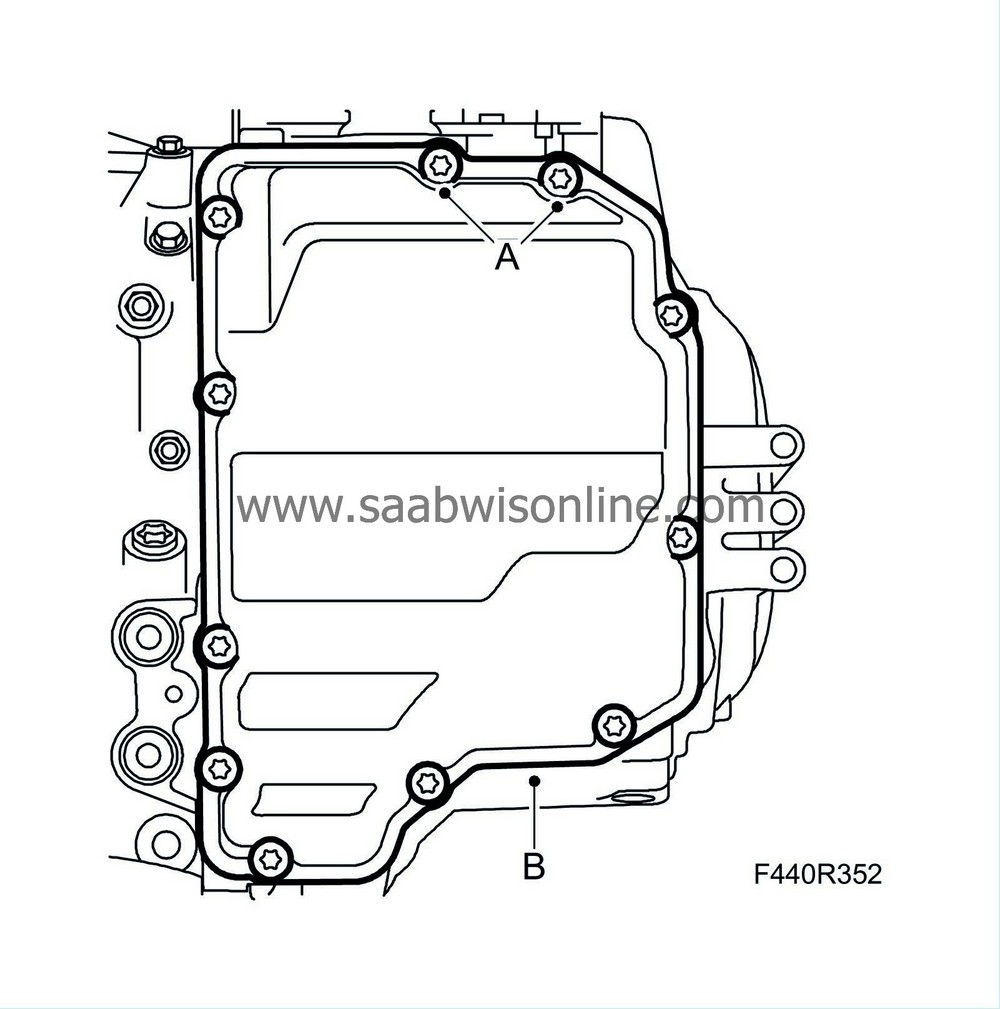
|
| • |
Raise the car and remove the remaining screws for the valve housing cover
|
| • |
Remove the cover (B) using a screwdriver.
|
||||||||||
| • |
Remove the
Valve housing
.
|
| To fit |
| 1. |
Lower the car to the floor.
|
|
| 2. |
Clean the contact surfaces.
|
|
| • |
Remove seal residue on the contact surfaces for the gearcase.
|
| • |
Clean the sealing surfaces from oil and grease using suitable cleaning agent.
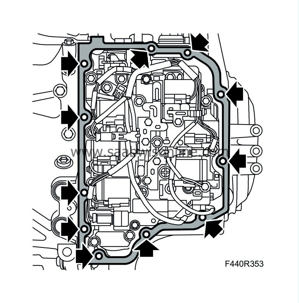
|
| 3. |
Fit the cover on the gearcase. If the cover is damaged then fit a new one.
|
|
| • |
Apply a bead using
90 543 772 Silicone flange sealant
onto the cover and fit the cover onto the gearcase.
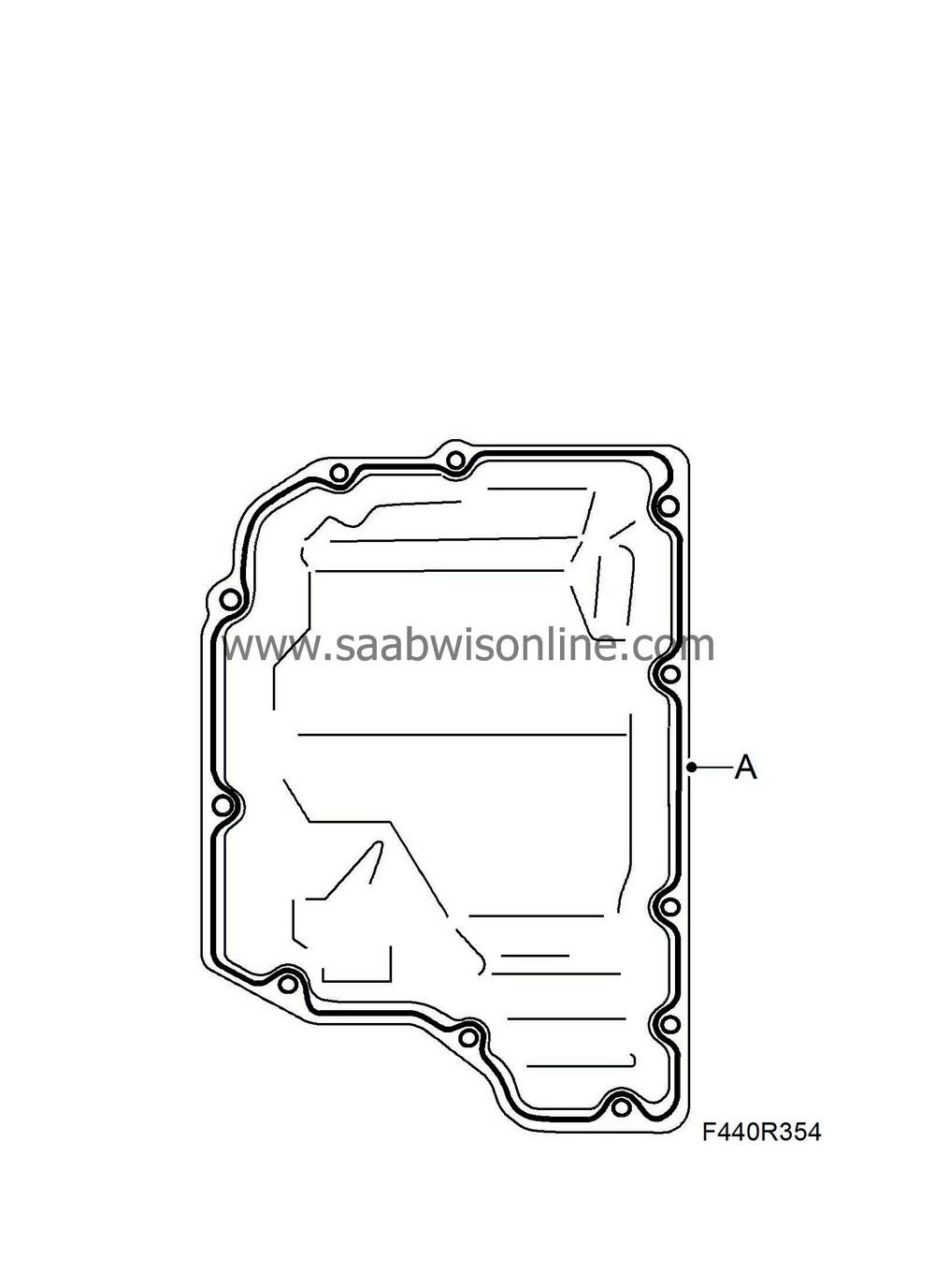
|
| • |
Tighten 2 x screws
|
| 4. |
Raise the car.
|
|
| 5. |
Fit and tighten the bolts alternately.
|
|
| • |
Fit 9 x screws.
|
| • |
Tighten 11 x screws alternately.
Tightening torque 13 Nm (10 lbf ft) |
| 6. |
Fit the oil cooler pipes to the gearbox.
|
|
| • |
Fit 1 x nut (A).
Tightening torque 6 Nm (4 lbf ft) 
|
| 7. |
Lower the car to the floor.
|
|
| 8. |
Fit the oil pipes in the oil cooler
|
|
| • |
Fit the lower pipe (B). Press until the pipe snaps into its position.

|
| • |
Press in the dust cover.
|
| • |
Fit the upper pipe (A) into the holder and the oil cooler. Press the pipe until it snaps into its position.
|
| • |
Press in the dust cover.
|
| 9. |
Remove the strap.
|
|
| 10. |
Fit the ground lead (A) and the clip (B) at the starter motor.
|
|
| • |
Fit 1 x nut.

|
| • |
Fit 1 x screw.
|
| 11. |
Fit the holder for the connector and the wiring harness.
|
|
| • |
Plug in 1 x connector (D).

|
| • |
Fit 1 x mounting (F).
|
| • |
Fit 2 x nuts (C)
|
| • |
Fit 1 x cable tie (E)
|
| • |
Plug in 3 x connectors (B)

|
| • |
Fit 1 x clip (A)
|
| • |
Fit 1 x cable tie
|
| 12. |
Fit the coolant hose to the thermostat housing pipe connection.
|
|
| • |
Fit 1 x hose clip (A).

|
| 13. |
Fit the bypass valve (B) to the turbo.

|
|
| • |
Fit 3 x screws.
|
||||||||||
| 14. |
Fit the intake hose to the turbo (A)

|
|
| • |
Fit 1 x hose clip
|
| • |
Fit the solenoid valve (C) to the turbo.
|
| 15. |
Fit the charge air pipe's hose to the turbo.
|
|
| • |
Fit 1 x hose clip (A).
|
| 16. |
Raise the car.
|
|
| 17. |
Fit the coolant hose (C) to the cooler.

|
|
| • |
Fit 1 x hose clip.
|
| 18. |
Fit the charge air pipe lower bracket (B).
|
|
| • |
Fit 1 x screw.
|
| 19. |
Clean and fit the hose on the charge air pipe and tighten the hose clip (A).
|
|
| 20. |
Remove the plug from the dipstick tube.

|
|
| 21. |
Lower the car to the floor.
|
|
| 22. |
Fill with gearbox oil
|
|
| • |
Remove the filler plug.

|
| • |
Connect
87 92 822 Oil filling equipment
to the oil filler hole.
|
| • |
Fill with automatic transmission fluid in accordance with the specification,
Weight, torque, fluid capacity and grade of fluid
until the oil flows out of the oil plug's dipstick tube.
|
||||||||||
| 23. |
Raise the car and fit the plug in the dipstick tube.
|
|
| 24. |
Lower the car to the floor.
|
|
| 25. |
Fill with 1 litre automatic transmission fluid in accordance with the specification,
Weight, torque, fluid capacity and grade of fluid
. Fit the filler plug.
Tightening torque 30 Nm (22 lbf ft) |
|
| 26. |
Fit
Battery cover, lower section, B284
and
Battery
.
|
|
| 27. |
Test pressurise the cooling system in accordance with
Cooling system, test pressurising
.
|
|
| 28. |
Fill with coolant and bleed the cooling system, in accordance with
Bleeding the cooling system
. Do not run the engine to operating temperature before checking the transmission fluid level.
|
|
| 29. |
Apply the parking brake and engage gear position P. Chock the wheels if a track lift is used. Connect an exhaust extractor.
|
|
| 30. |
Start the engine. Move the selector lever from P to D and then from D to P. Allow the selector lever to remain in each gear position (N and R) for at least 2 seconds while applying the foot brake. Repeat this procedure twice.
|
|
| 31. |
Connect Tech 2. Run the engine until the temperature reaches 35-45 °C in the "Read values" menu in TCM.
|
|
| 32. |
Raise the car with the gear selector lever in position P and the engine at idling speed. Remove the level plug and check the fluid level. Fill as necessary. Fit the plug when the fluid stops flowing.
Tightening torque 8 Nm (6 lbf ft) |
|
| 33. |
CV:
Fit
Chassis reinforcement, front subframe, CV
|
|
| 34. |
CV:
Fit
Spoiler shield, front
.
|
|
| 35. |
Carry out
Measures after disconnecting the battery
.
|
|

 Warning

