(645-2619) Securing the wiring harness to the power steering unit (745)
|
MODIFICATION INSTRUCTION
|
|
Bulletin Nbr:
|
645-2619
|
|
Date:
...........
|
June 2006
|
|
Market:
|
Enligt separat lista
|
|
|
Securing the wiring harness to the power steering unit (745)
|
|
Customer Satisfaction Program 154 47
|
Cars in stock must be rectified before delivery.
A personal communication must be sent to the owners of cars already delivered requesting them to get in touch with the nearest Saab garage as soon as possible to have the fault rectified.
Saab 9-3 M05-06 LHD with engine alternative Z19 within Vehicle Identification Number range 51003946 - 61017226 and equipped with auxiliary/parking heater.
Incorrect routing of the wiring harness to the power steering unit. In some cases this results in the wiring harness making contact with the exhaust pipe to the auxiliary/parking heater, which could cause damage to the wiring harness through melting.
If the wiring harness is not damaged:
92 150 191 Cable tie (x 1)
If the wiring harness shall be repaired:
45 43 443 Chafe guard 37 cm, sufficient for 4 cars
Heat resistant fabric tape
If the wiring harness shall be replaced:
92 150 191 Cable tie (x 2), only M05
92 150 191 Cable tie (x 1), only automatic
M05, with particle filter:
12 804 421 Wiring harness, engine, Z19DT, Man
12 803 390 Wiring harness, engine, Z19DTH, Man
12 803 391 Wiring harness, engine, Z19DTH, Aut
M05, without particle filter:
12 760 059 Wiring harness, engine, Z19DT, Man
12 760 058 Wiring harness, engine, Z19DTH, Man
M06, with particle filter:
12 762 777 Wiring harness, engine, Z19DTH, Man
12 762 778 Wiring harness, engine, Z19DTH, Aut
12 762 779 Wiring harness, engine, Z19DT, Man
M06, without particle filter:
12 762 780 Wiring harness, engine, Z19DTH, Man
12 762 781 Wiring harness, engine, Z19DT, Man
For fitting the modification identity plate:
12 785 148 Modification identity plate
93 160 907 Cleaning agent Motip Dupli, aerosol 400 ml (sufficient for 50-100 cars).
Checking the modification identity plate (not US/CA)
Before proceeding, check box B2 of the modification identity plate. From and including M04, the car's Warranty and Service Book contains the "Table of Modifications". A modification identity plate must be fitted in accordance with the section "Fitting the modification identity plate" where local directives require the marking of the car. If the box is not marked, continue as follows.
|
2.
|
M05:
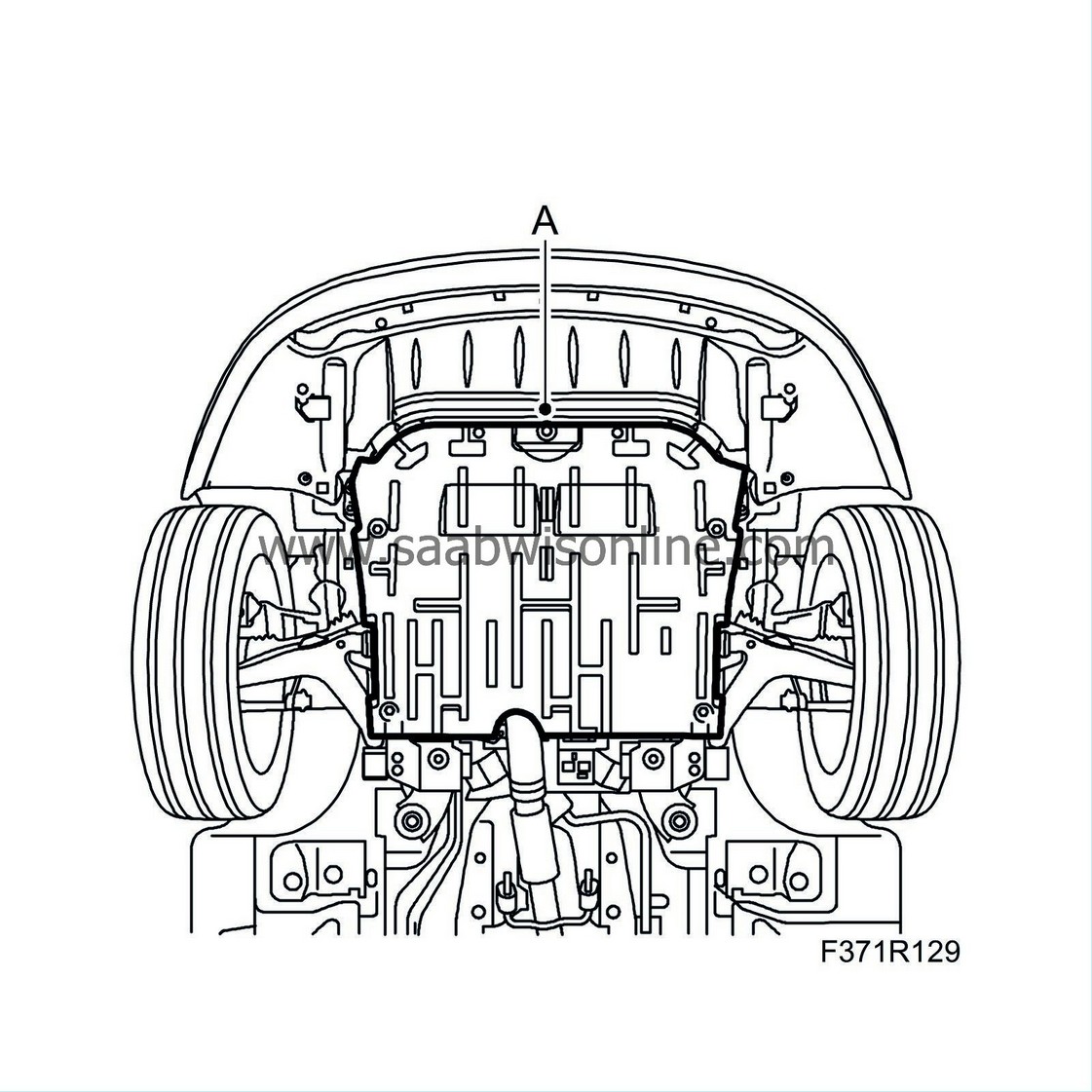
Remove the lower engine cover (A).
|
|
3.
|
Check if the wiring harness is damaged.
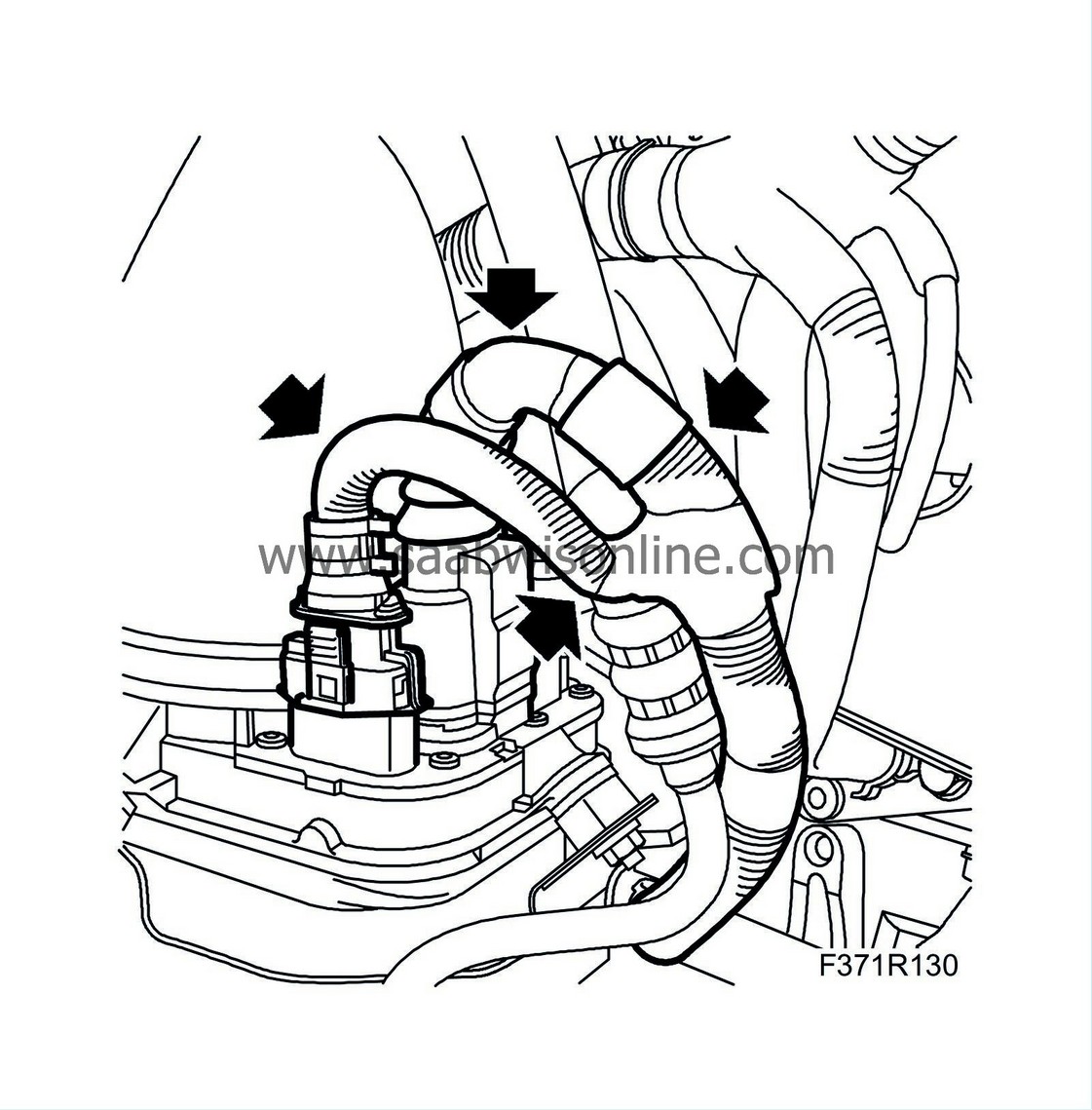
- If the wiring harness or casing is not damaged, carry out steps 4-6.
- If only the casing for the wiring harness is damaged, carry out steps 7-19.
- If the wiring harness is damaged, carry out "Replacing the wiring harness".
|
|
4.
|
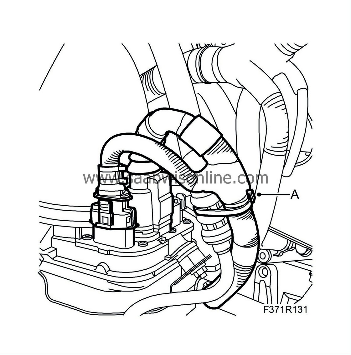
Secure the wiring harness (A) together with the power steering hose using a cable tie.
|
|
5.
|
M05:
Fit the lower engine cover (A).

|
|
7.
|
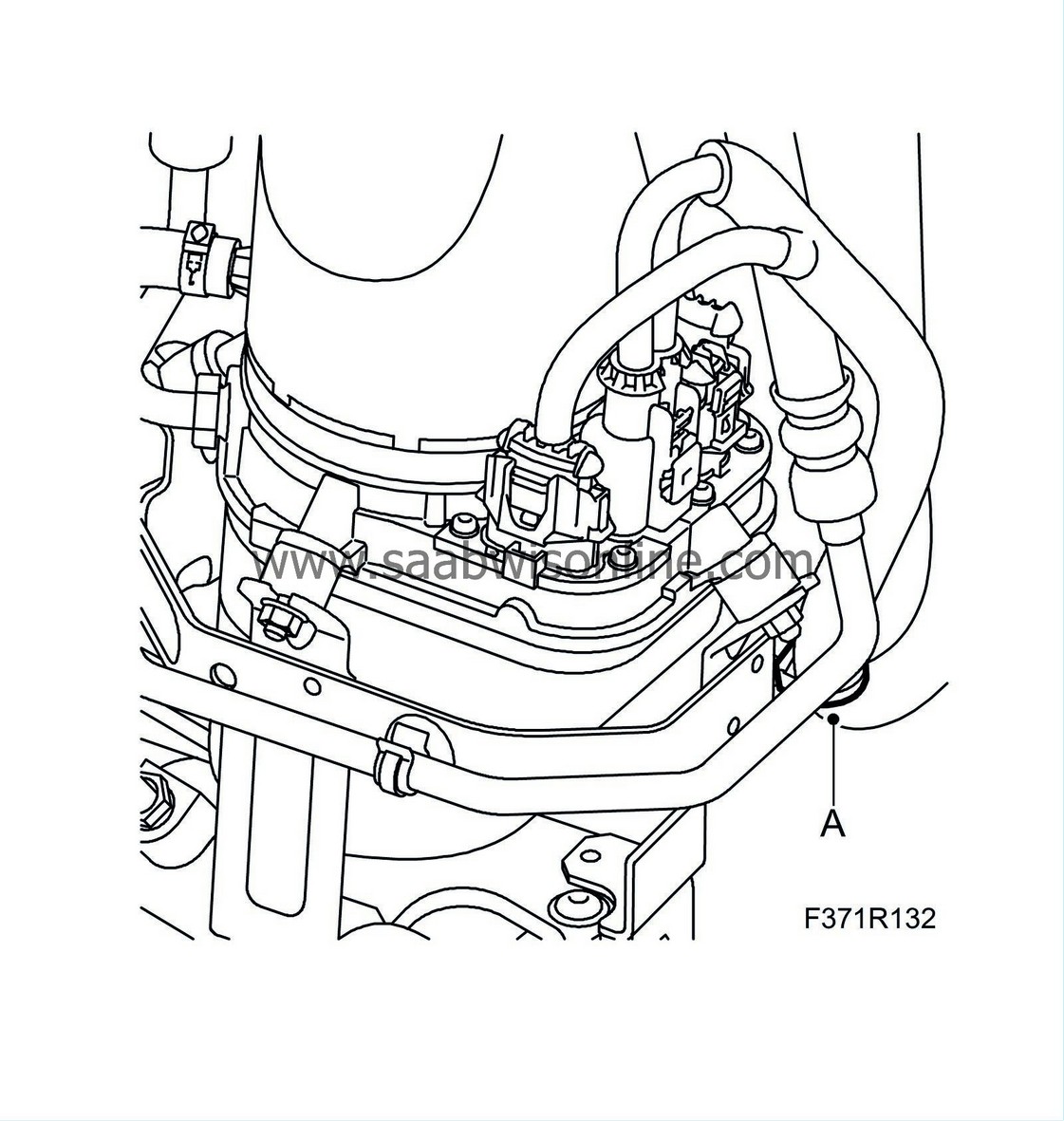
Remove the cable clip (A) from the bracket.
|
|
8.
|
M05:
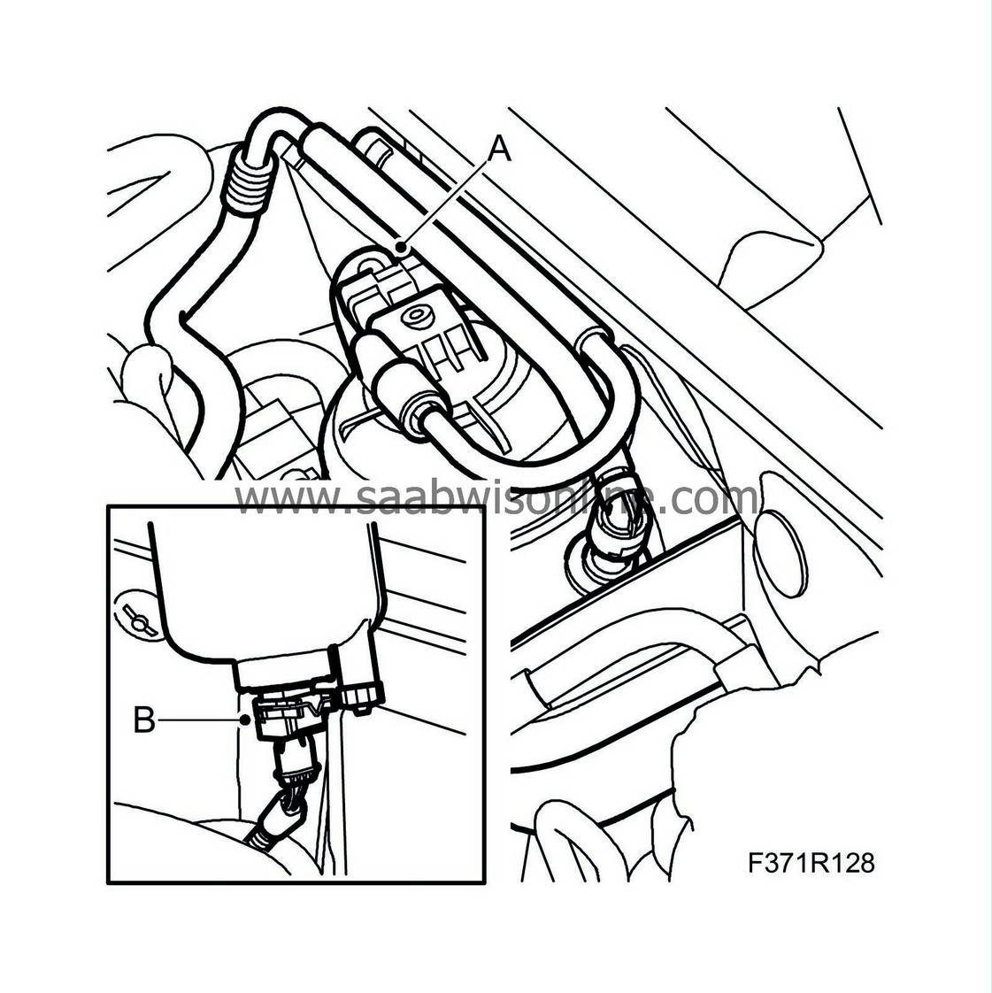
Unplug the upper connector (A) from the fuel filter. Lift up the fuel filter. Unplug the lower connector (B) and move the fuel filter to one side.
|
|
9.
|
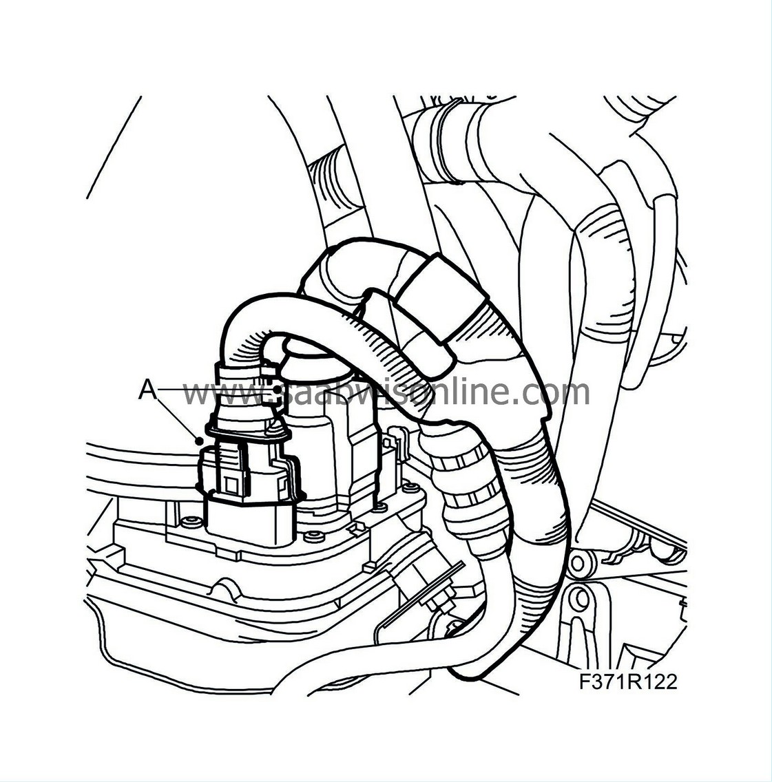
Unplug the connectors (A) from the power steering pump and route the wiring harness up.
|
|
10.
|
Cut off an approx. 9 cm piece from the chafe guard 45 43 443.
|
|
11.
|
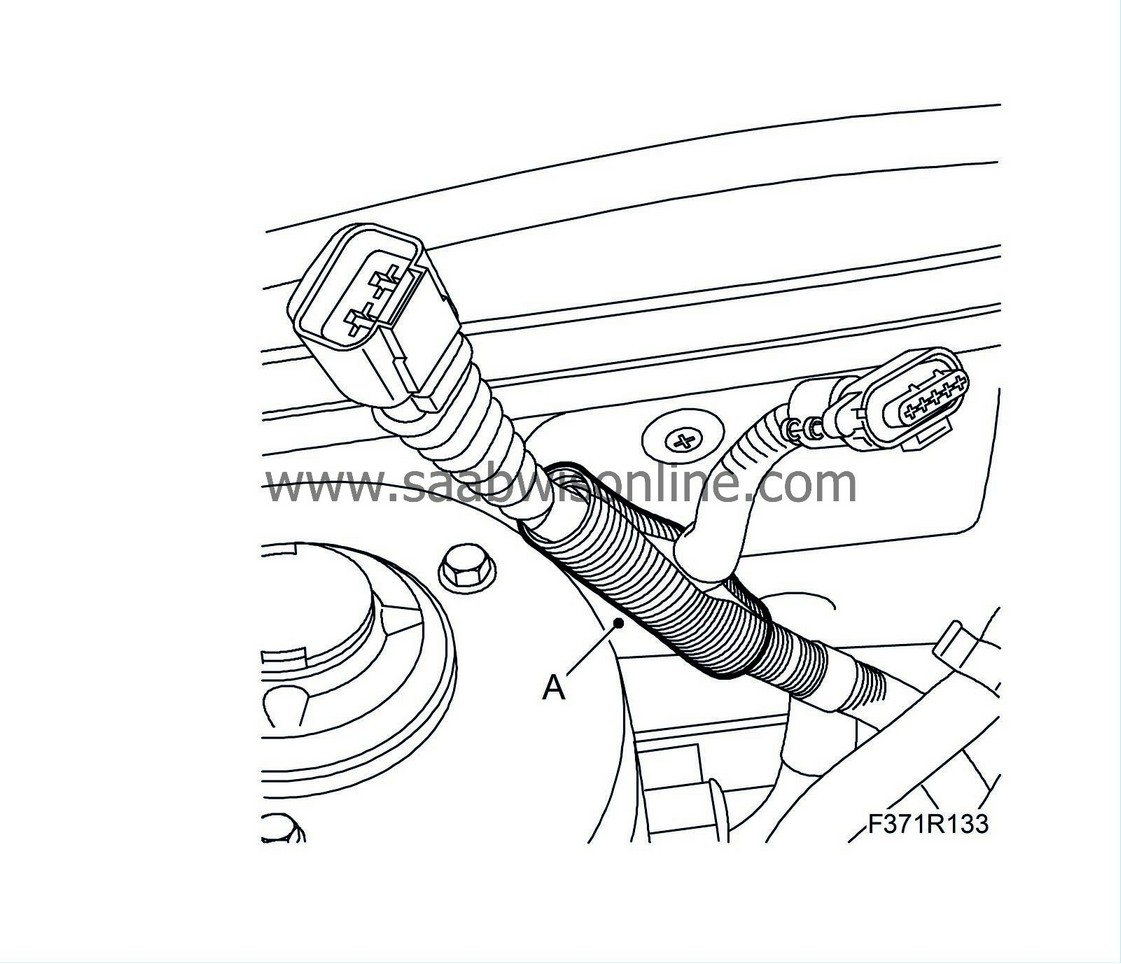
Fit the chafe guard (A) over the damaged section of the thick wiring harness.
|
|
12.
|
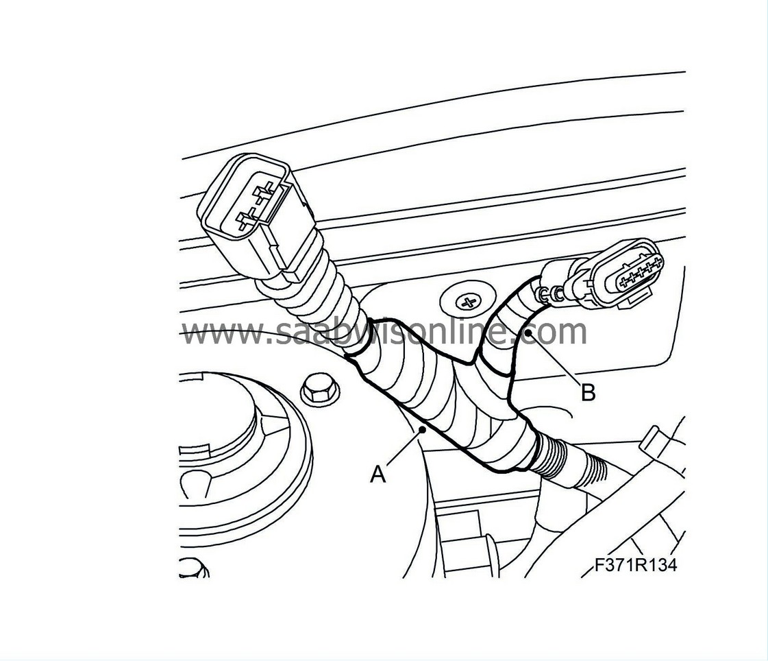
Wind heat resistant fabric tape around the chafe guard (A) and the thin wiring harness (B).
|
|
13.
|
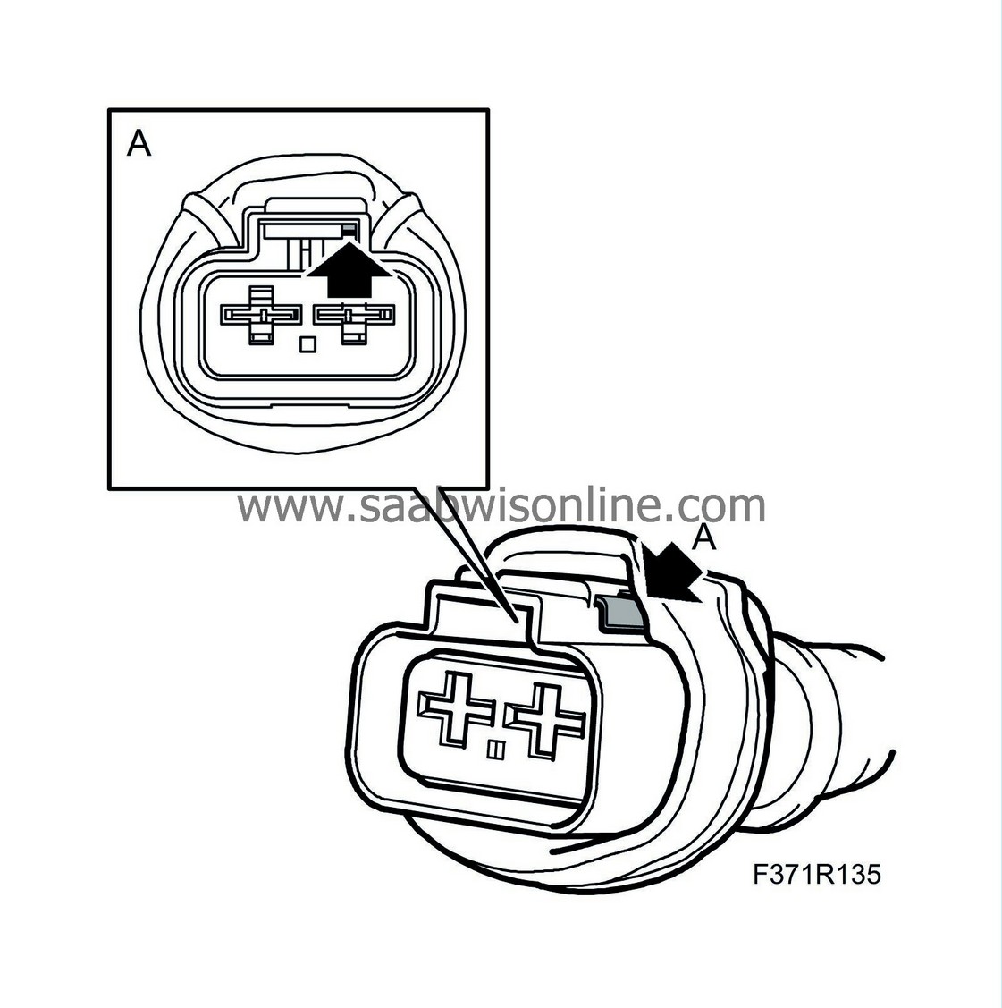
Check the position (A) of the catch on the connector so that it locks when connected.
|
|
14.
|
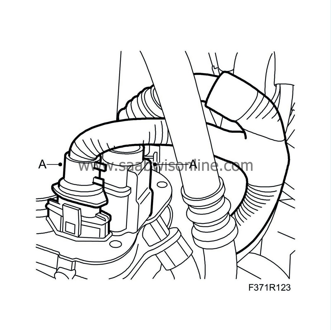
Route the wiring harness to the power steering pump between the engine and the power steering hose. Connect the clip and the connectors (A) to the power steering pump.
|
|
15.
|
M05:
Plug in the lower connector (B) to the fuel filter, fit the fuel filter and plug in the upper connector (A).

|
|
17.
|
Fit the cable clip (A) to the bracket.

|
|
18.
|
M05:
Fit the lower engine cover (A).

|
|
Replacing the wiring harness
|
To remove:
|
2.
|
M05:
Remove the upper engine cover, the insulation and the battery cover.
|
|
|
•
|
Disconnect the battery's negative cable.
|
|
|
•
|
Disconnect the positive cable that runs to the fuse box from the positive cable terminal on the battery.
|
|
|
•
|
Disconnect the battery's positive cable.
|
|
|
•
|
Remove the screw to the battery's locking lug and lift out the battery.
|
|
4.
|
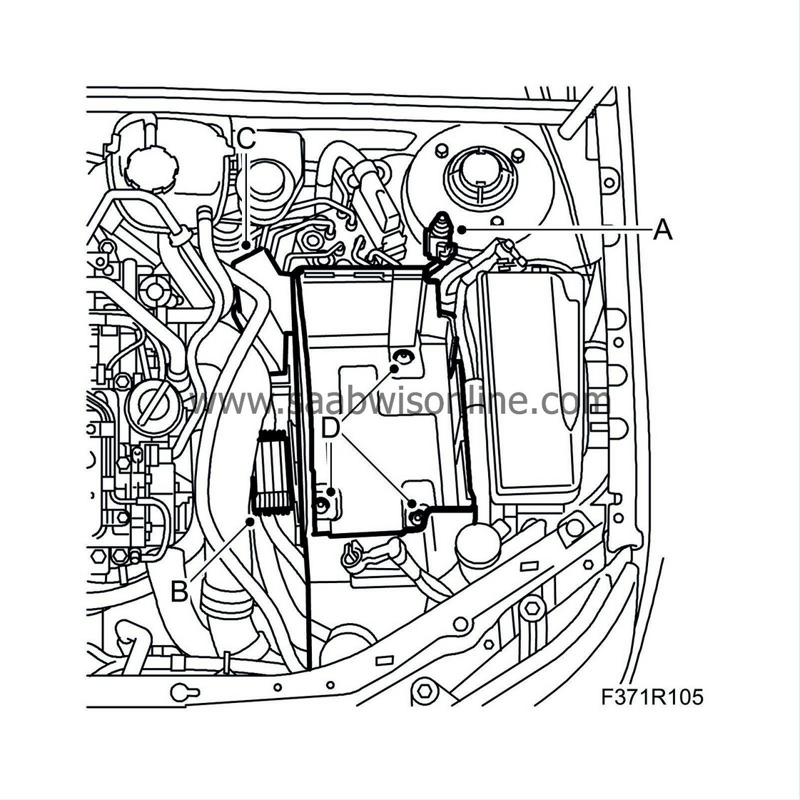
Remove the battery tray and components:
|
|
|
•
|
Disconnect the bonnet connector's electrical connection (A).
|
|
|
•
|
Remove the glow plug relay (B).
|
|
|
•
|
Remove the fuse holder (C).
|
|
|
•
|
Remove the wiring harness' cable tie from the battery tray.
|
|
|
•
|
Remove the battery tray (D).
|
|
5.
|
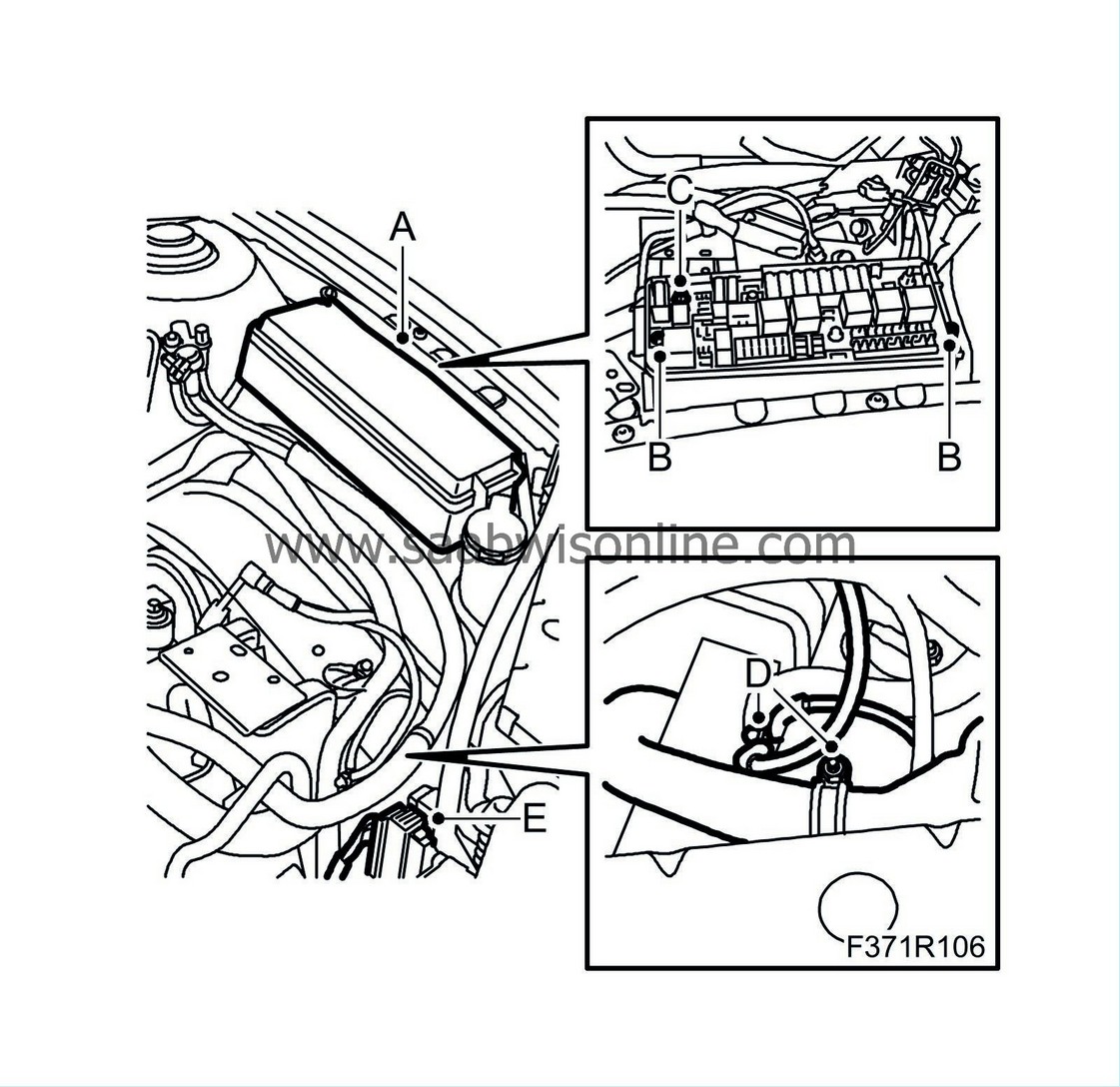
Undo the wiring harness and separate the fuse box:
|
|
|
•
|
Remove the cover to the fuse box (A).
|
|
|
•
|
Separate the fuse box (B).
|
|
|
•
|
Remove the front screw (C) on the fuse box.
|
|
|
•
|
Unplug the front connector under the fuse box.
|
|
|
•
|
Remove the hose clip (D) and the ground connection (D) to the wiring harness.
|
|
|
•
|
Unplug the connector (E) on the structural member.
|
|
6.
|
Man:
Disonnect the connection to the reversing light switch.
Aut:
Remove the cable tie that secures the wiring harness to the reversing light switch.
|
|
7.
|
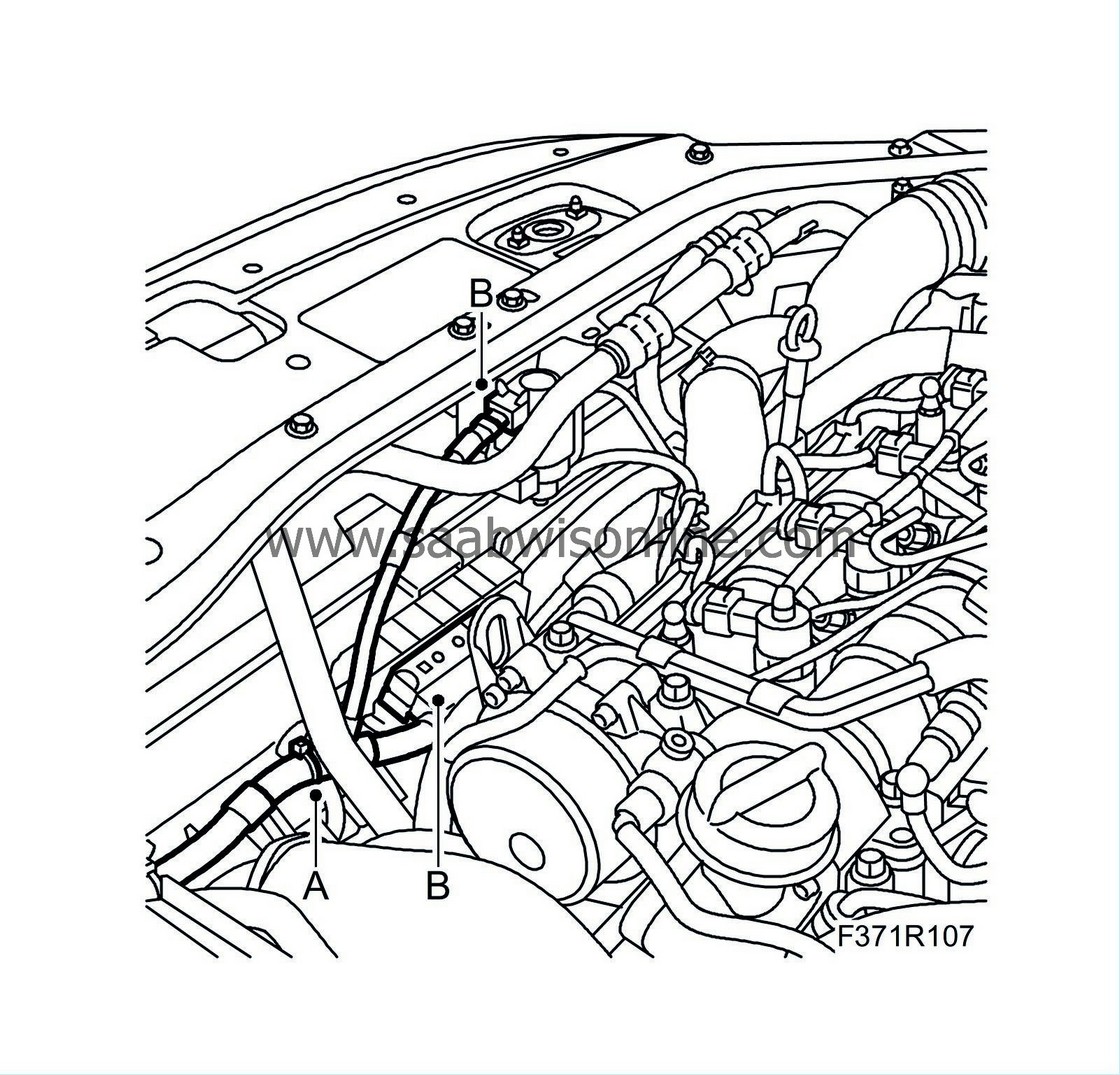
Remove the cable clips (A) and the connectors (B) to the cooling fans and the charge air valve.
|
|
8.
|
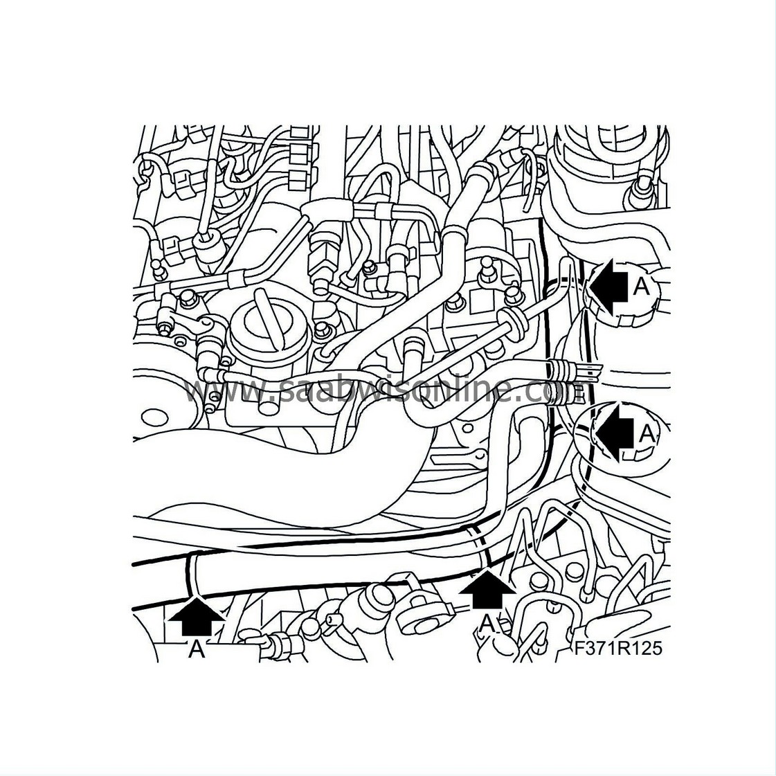
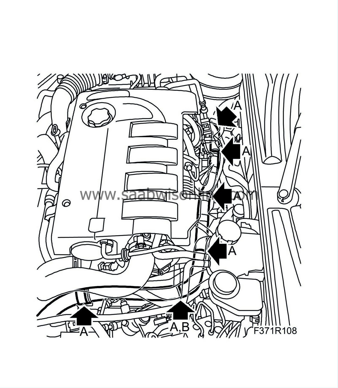
Remove the cable clips (A) and the cable tie (B) on the left-hand and rear of the engine.
M05:
M06:
|
|
9.
|
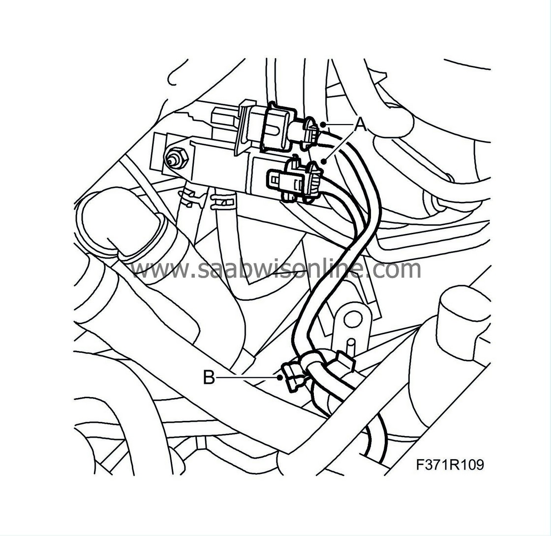
Unplug the connectors (A) to the pressure sensor for the particle trap and the temperature sensor.
M06:
Remove the clip (B) from the water hose.
|
|
10.
|
M06:
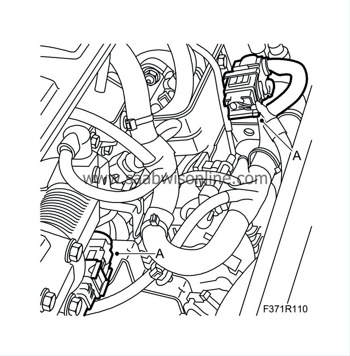
Unplug the connectors (A) on the rear of the engine.
|
|
11.
|
M05:
Unplug the connectors (A) to the fuel filter and remove the cable clip.

|
|
12.
|
M05:
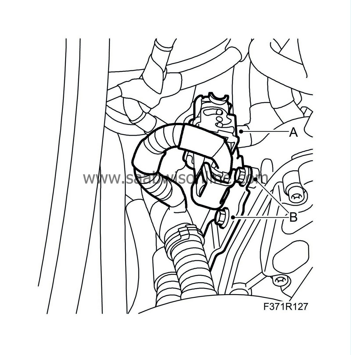
Remove the bracket (B) in order to access the clips (A) securing the wiring harness. Remove the clips.
|
|
13.
|
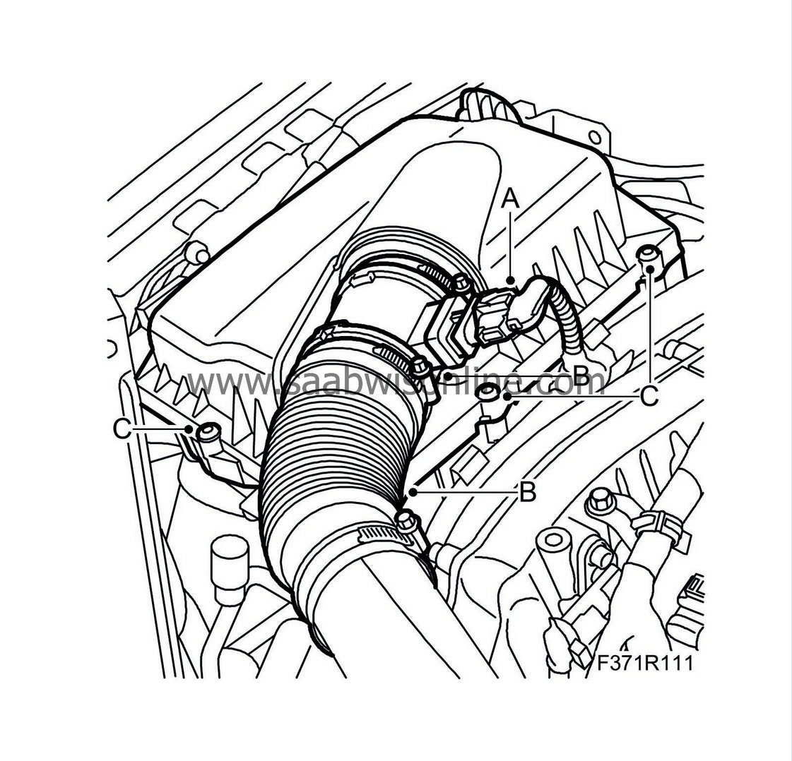
Remove the air filter housing:
|
|
|
•
|
Unplug the connector (A) from the mass air flow sensor.
|
|
|
•
|
Undo the hose from the mass air flow sensor (B).
|
|
|
•
|
Remove the screws (C) and lift out the air filter housing.
|
|
14.
|
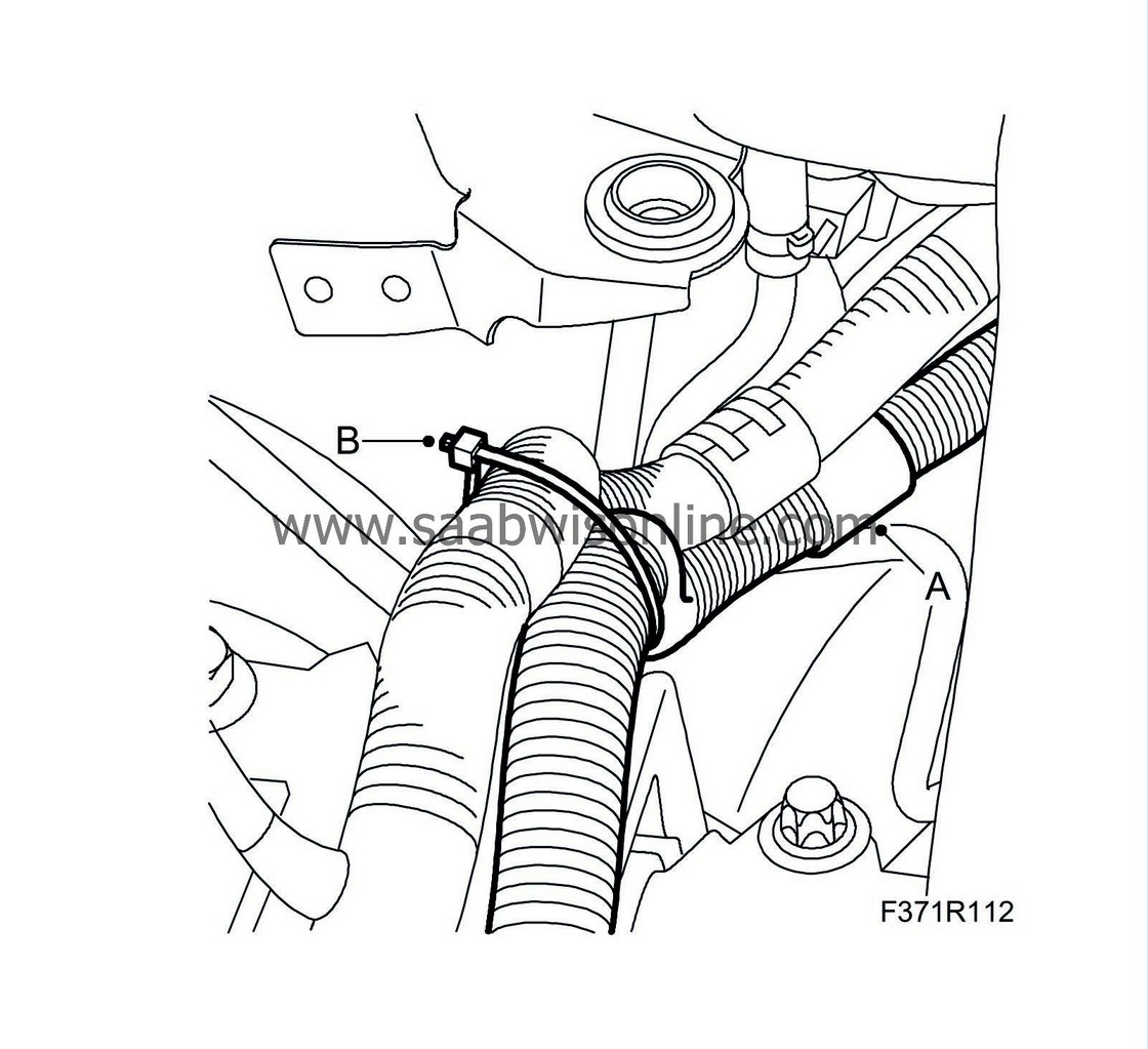
Remove the clips (A) on the right-hand rear structural member and the cable tie (B).
|
|
15.
|
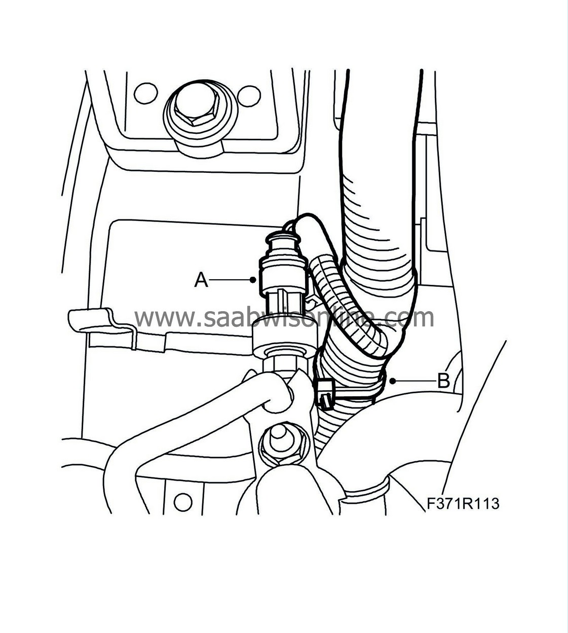
Unplug the connector (A) on the A/C pipe and remove the clip (B) on the right-hand structural member.
|
|
16.
|
Remove the clips (A) on the upper radiator member.

|
|
17.
|
Raise the car to a suitable working height.
|
|
18.
|
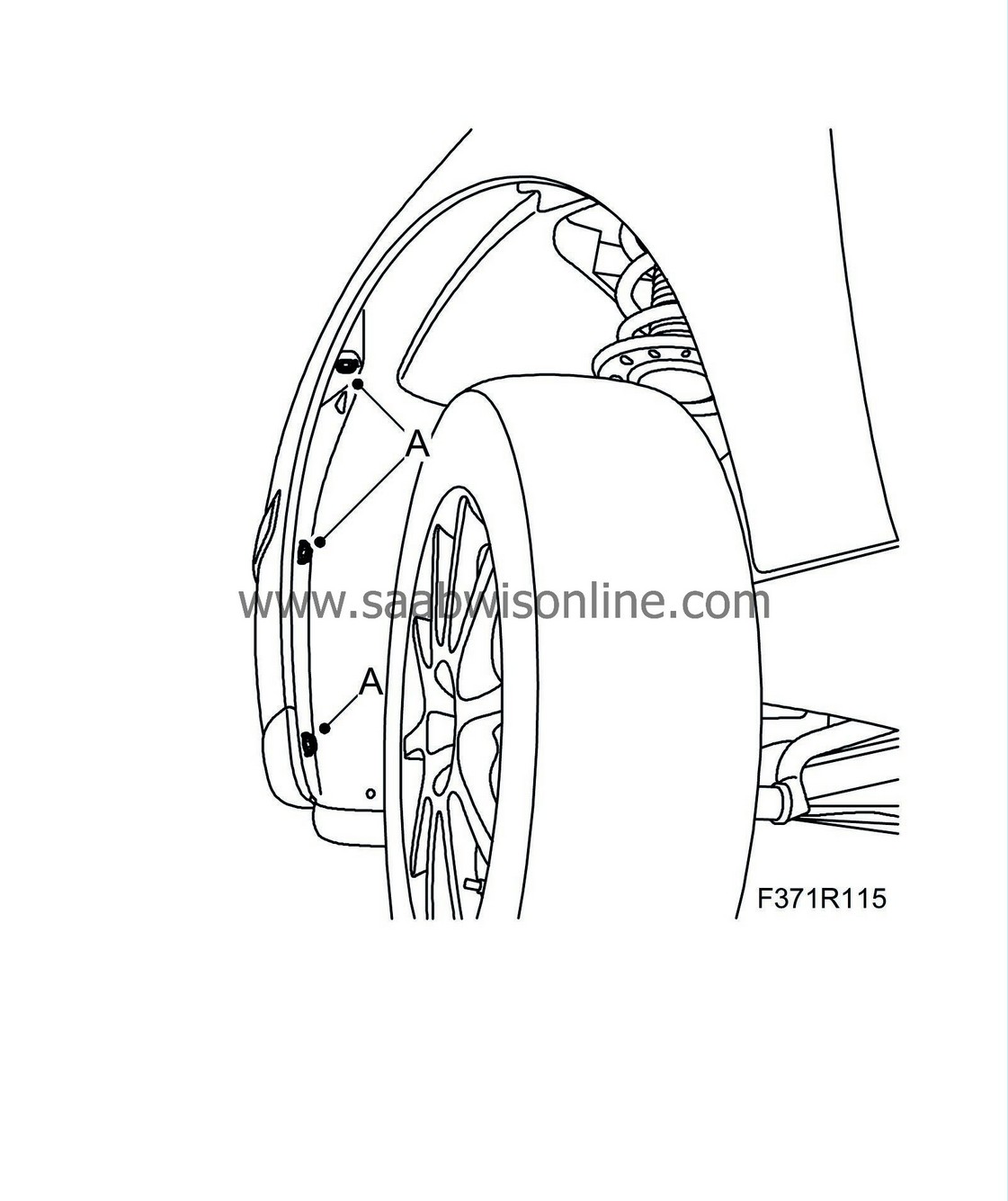
Remove the bumper's screws in the wing liner (A).
|
|
19.
|
Remove the spoiler shield (A). Unplug connector (B) and connector (C).
M06:
Remove the lower engine cover (D).

|
|
20.
|
Cars with headlamp washers:
Undo the washer hose, hang it up and seal it if necessary.
|
|
21.
|
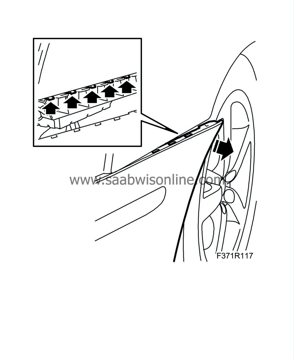
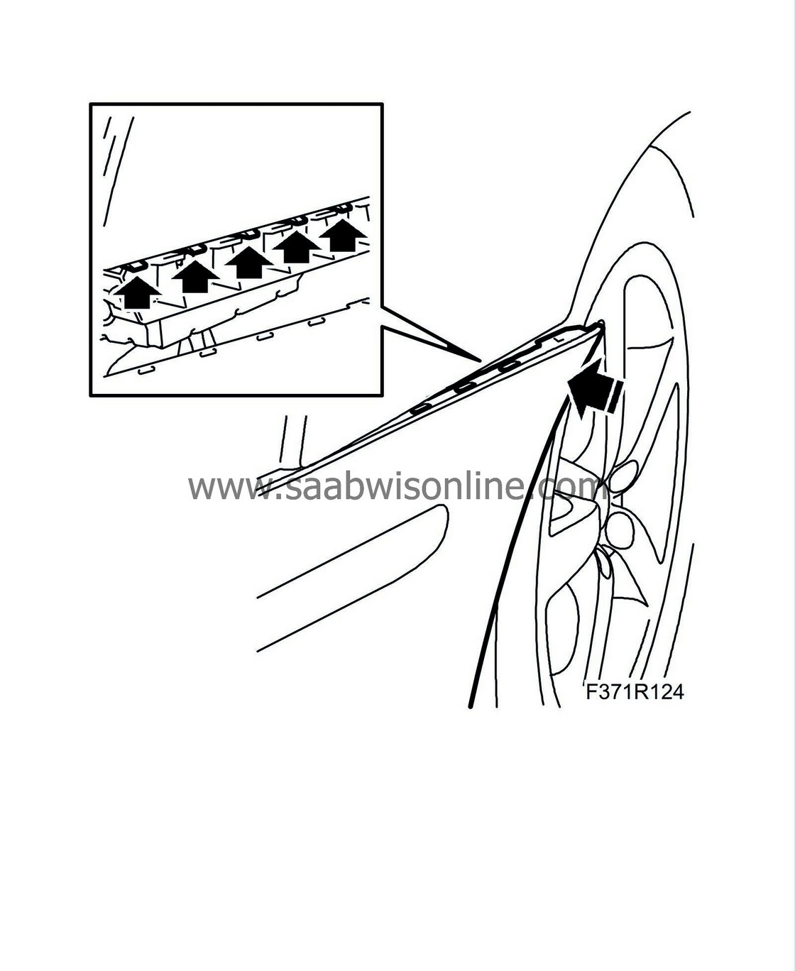
Bend out the corner of the bumper shell from the holder's brackets and lift the bumper shell off.
|
|
22.
|
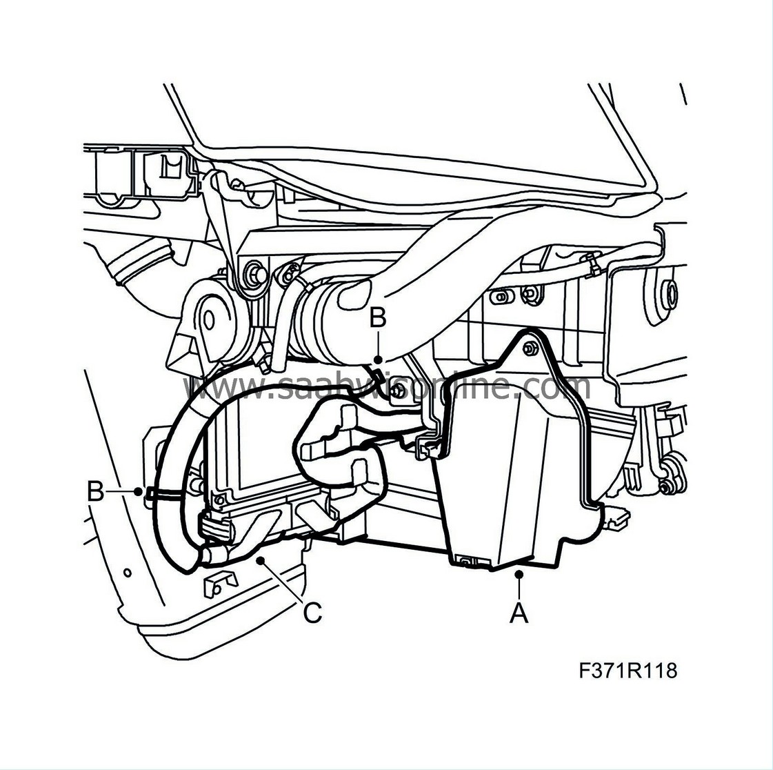
Remove the right-hand side cover and undo the wiring harness:
|
|
|
•
|
Remove the right-hand side cover (A).
|
|
|
•
|
Remove the cable ties (B) that secure the wiring harness around the control unit.
|
|
|
•
|
Disconnect the right-hand connection (C) to the control unit (595).
|
|
23.
|
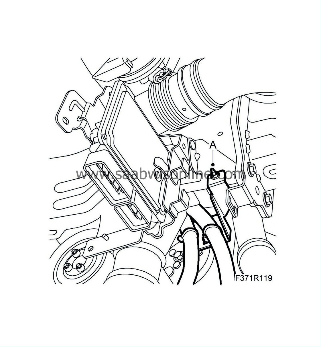
Remove the bracket (A) that protects the wiring harness for the A/C compressor. Expose the wiring harness so that it hangs freely down into the engine bay.
|
|
24.
|
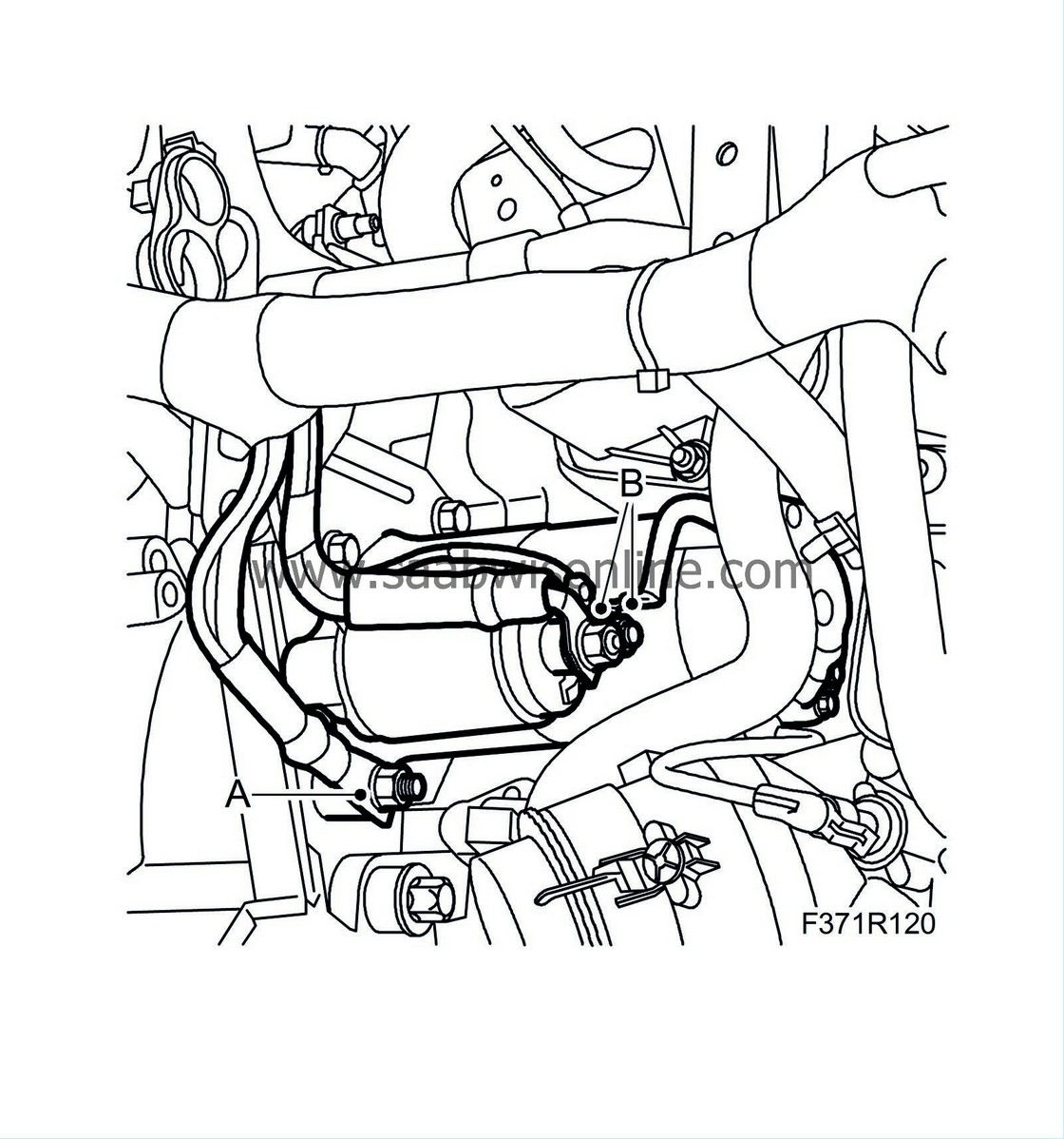
Disconnect the ground connection (A) on the engine.
|
|
26.
|
Disconnect the electrical connections (B) from the starter motor.
|
|
27.
|
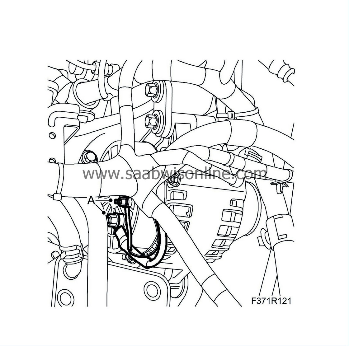
Disconnect the electrical connections (A) from the generator.
|
|
28.
|
Unplug the connectors (A) from the power steering pump and remove the clip that secures the wiring harness.

|
|
29.
|
Route the wiring harness up.
|
To fit:
|
1.
|
Locate the new wiring harness in position in the engine bay and route down the section to be connected to the control unit.
|
|
2.
|
Route the wiring harness to the power steering pump between the engine and the power steering hose. Plug in the connectors (A) to the power steering pump and fit the clip.

|
|
3.
|
Connect the electrical connections (A) to the generator.

|
|
4.
|
Connect the electrical connections (B) to the starter motor.

|
|
6.
|
Connect the ground connection (A) on the engine.
|
|
7.
|
Fit the bracket (A) that protects the wiring harness for the A/C compressor.

|
|
8.
|
Fit the right-hand side cover and secure the wiring harness:

|
|
|
•
|
Fit the right-hand side cover (A).
|
|
|
•
|
Fit the cable ties (B) that secure the wiring harness around the control unit.
|
|
|
•
|
Connect the right-hand connection (C) to the control unit.
|
|
9.
|
Fit the bumper shell:
|
|
|
•
|
Check that the cellular block is positioned correctly in the shell.
|
|
|
•
|
Align the bumper. Press the shell backwards and press the shell's clips into the holder.
|
|
10.
|
Cars with headlamp washers:
Connect the washer hose.
|
|
11.
|
Fit the lower engine cover (D), the connector (C) and plug in connector (B). Fit the spoiler shield (A).

|
|
12.
|
Fit the bumper's screws in the wing liner (A).

|
|
14.
|
Fit the upper radiator member's clips (A).

|
|
15.
|
Plug in the connector (A) on the A/C pipe and fit the clip (B) on the right-hand structural member.

|
|
16.
|
Fit the clips (A) on the right-hand rear structural member and the cable tie (B).

|
|
17.
|
Fit the air filter housing:

|
|
|
•
|
Fit the air filter housing (C).
|
|
|
•
|
Connect the hose to the mass air flow sensor (B).
|
|
|
•
|
Plug in the connector (A) to the mass air flow sensor.
|
|
18.
|
M05:
Plug in the connectors to the fuel filter and fit the cable clip.

|
|
19.
|
M05:
Fit the cable clips (A) and the bracket (B).

|
|
20.
|
M06:
Plug in the connectors (A) on the rear of the engine.

|
|
21.
|
Plug in the connectors (A) to the pressure sensor for the particle trap and the temperature sensor.
M06:
Fit the clip (B) to the water hose.

|
|
22.
|
Fit the clips (A) and the cable tie (B) that secure the wiring harness on the left-hand side and the rear of the engine.
M05:

M06:

|
|
23.
|
Fit the clips (A) and the connections (B) to the cooling fans and the charge air valve.

|
|
24.
|
Man:
Connect the connection to the reversing light switch.
Aut:
Fit the cable tie that secures the wiring harness to the reversing light switch.
|
|
25.
|
Fit the wiring harness and the fuse box:

|
|
|
•
|
Plug in the connector (E) on the structural member.
|
|
|
•
|
Fit the hose clip (D) and the ground connection (D) to the wiring harness.
|
|
|
•
|
Plug in the front connector under the split fuse box.
|
|
|
•
|
Fit the front screw on the fuse box (C).
|
|
|
•
|
Fit the cover to the fuse box (A).
|
|
26.
|
M06:
In order to avoid chafing damage to the wiring harness while fitting the fuse holder to the battery tray, the fuse holder bracket must be adjusted:
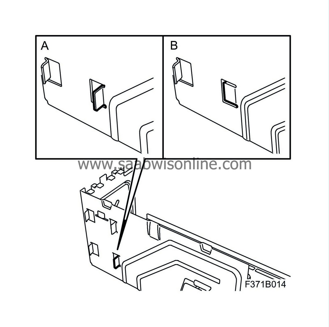
|
|
|
•
|
Straighten out (A) and bend in (B) the fuse holder's front lower bracket.
|
|
27.
|
Fit the battery tray and components:

|
|
|
•
|
Fit the battery tray (D).
|
|
|
•
|
Fit the wiring harness' cable tie to the battery tray.
|
|
|
•
|
Fit the fuse holder (C).
|
|
|
•
|
Fit the glow plug relay (B).
|
|
|
•
|
Connect the bonnet connector's electrical connection (A).
|
|
|
•
|
Position the battery and fit the screw to the battery's locking lug.
|
|
|
•
|
Connect the battery's positive cable.
|
|
|
•
|
Connect the positive cable from the fuse box to the positive cable terminal on the battery.
|
|
|
•
|
Connect the negative cable to the battery.
|
|
29.
|
M05:
Fit the insulation, the upper engine cover and the battery cover.
|
|
30.
|
Check the alignment of the bumper and adjust as necessary.
|
|
31.
|
Carry out the Procedure after disconnecting the battery, in accordance with WIS - Electrical system - Wiring harness and components - Fault diagnosis, general.
|
|
Marking the modification identity plate
|
After carrying out the procedure, box B2 on the modification identity plate must be marked. From and including M04 the car's Warranty and Service Book contains the "Table of Modifications". Mark the box with the number "7" if the procedure was carried out by the importer or with the number "8" if carried out by the dealer.
|
Fitting the modification identity plate
|
|
Note
|
|
A modification identity plate must only be fitted where local directives require the marking of the car.
|
Fit the modification identity plate in accordance with WIS
9-3 (9440) M04 - General - General - Technical data - Plates and labels
|
Warranty/Time Information
|
See separate information.


