(870-2700) Worn symbols on the ACC panel's buttons
Symptom: The symbols on the buttons wear out and become illegible.
|
TECHNICAL SERVICE BULLETIN
|
|
Bulletin Nbr:
|
870-2700
|
|
Date:
...........
|
April 2008
|
|
Market:
|
all
|
|
|
Worn symbols on the ACC panel's buttons
|
Saab 9-3 M03-M06 up to and including Vehicle Identification Number 61109897 with ACC panel
Saab 9-3 CV M04-M06 up to and including Vehicle Identification Number 66007222 with ACC panel
Paint may flake from the ACC panel buttons due to an adhesion problem.
In the case of customer complaint, the following procedure must be carried out.
Symptom description
The symbols on the buttons wear out and become illegible.
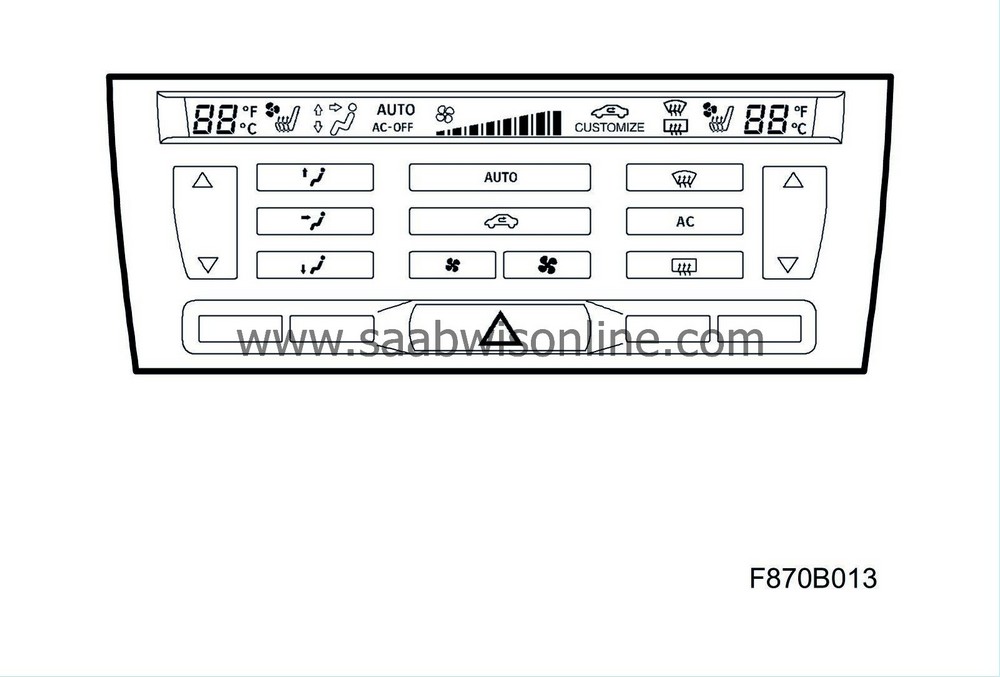
12 781 997 Keypad ACC, without symbols for electrically heated seats (1 button frame and 3 loose buttons)
12 781 996 Keypad ACC, with symbols for electrically heated seats (1 button frame and 3 loose buttons)
12 781 994 Front panel ACC, if necessary.
|
Note
|
|
All buttons must be replaced. The replacement buttons have an improved surface finish.
|
|
1.
|
Remove the ACC panel according to WIS - 9-3 (9440) - 8. Body - Air Condition Control - Automatic climate control - ACC unit (216).
|
|
2.
|
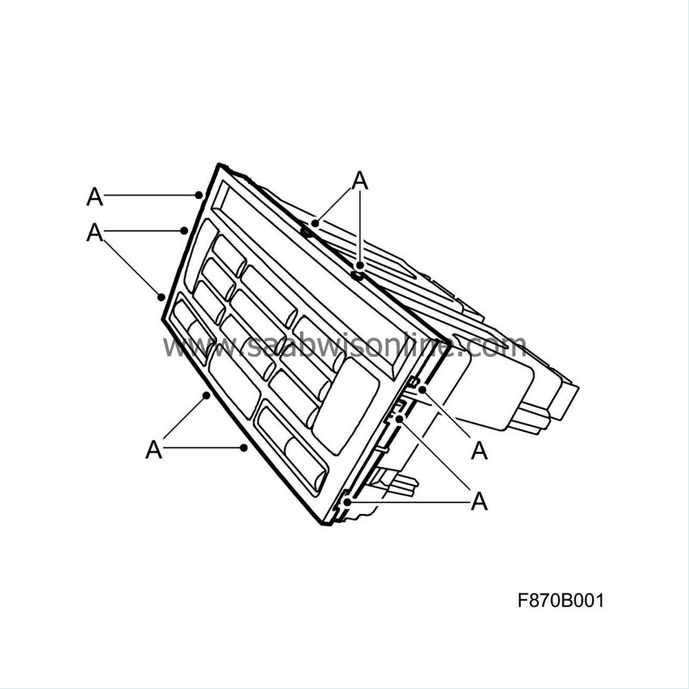
Remove the front panel from the catches (A) on the ACC unit as follows:
|
|
|
•
|
Insert a small screwdriver between the front panel and the catches on the ACC unit.
|
|
|
•
|
Carefully pry the front panel from the catches using the screwdriver. Keep the front panel in position with your hand or with 82 93 474 Removal tool.
|
|
|
•
|
Continue to pry the next catch until the front panel releases from the unit.
|
Note
|
|
If the front panel breaks, replace it with a new panel.
|
|
Note
|
|
Note how the buttons are fitted on the ACC unit. Exercise care when removing the buttons so that the display is not damaged. Do not touch the display.
|
|
|
3.
|
Position the ACC unit as it is fitted in the car on a workbench.
|
|
4.
|
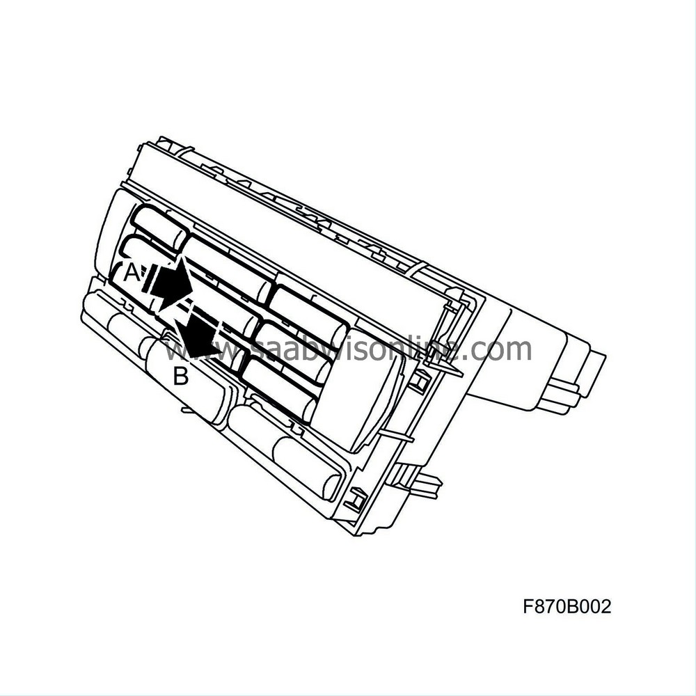
Carefully remove all the buttons except the temperature buttons from the ACC unit. Proceed as follows:
|
|
|
•
|
Press the button inwards (A) and then move the button downwards (B). The button can then be removed.
|
|
|
•
|
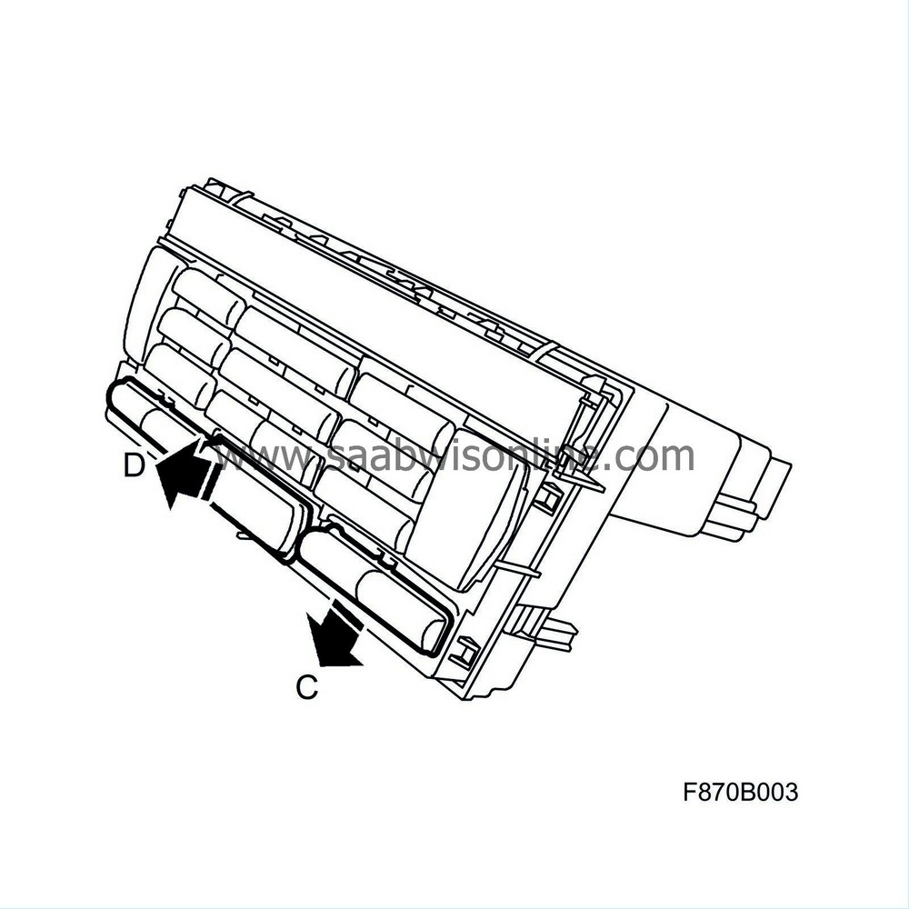
Dummy buttons and buttons for the electrically heated seats (C) must be pressed downwards. The button for the hazard flashers (D) should be pulled straight out.
|
|
5.
|
Remove the temperature buttons using a screwdriver. Press the button inwards towards the centre (A) and carefully lift off the button using the screwdriver (B), move the button outwards (C) and remove the button.

|
|
6.
|
Check whether the mountings on the temperature button (A) have been bent during removal. If they have been bent, they should be carefully bent back to their original positions (B) (90 degrees). A bent mounting results in play and the temperature button will rattle.

|
|
7.
|
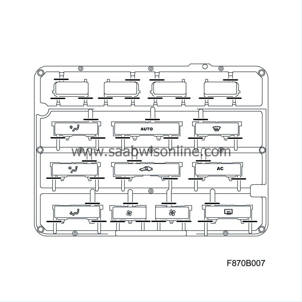
Take out the frame with the new buttons.
|
Note
|
|
There are two different sets of buttons, one with and one without symbols for the electrically heated seats.
|
Keypad 12 781 996 with symbols for electrically heated seats:
|
|
|
•
|
On buttons with symbols for electrically heated seats there must be no pins protruding from the sides of the buttons. The pins at the rear are to be kept.


|
|
|
•
|
On the other buttons both with and without symbols only the links between the frame and the buttons are to be cut off. Other pins on the sides and rear are to remain.
|
|
|
•
|
On buttons without symbols, no pin is to be cut off as these are to be fixed dummy buttons.
Keypad 12 781 997 without symbols for electrically heated seats:
|
|
|
•
|
On buttons both with and without symbols only the links between the frame and the buttons are to be cut off. Other pins on the sides and on the rear are to remain.
|
|
|
•
|
On buttons without symbols, no pin is to be cut off as these are to be fixed dummy buttons.
|
|
8.
|
Compare with the removed original buttons. Place the new buttons, which are to be cut, so that they cannot be positioned incorrectly when fitted on the ACC panel. Make sure they are not mixed together with the old buttons which are to be discarded.
|
|
9.
|
Cut off the links between the frame and the buttons. Start by cutting off the buttons using wire cutters. Then use a modelling knife to fine trim the buttons. Note that on the frame with buttons for the electrically heated seats, the outside and the top side of the buttons are to be fine trimmed (the pins that have not been links to the frame). This must not be performed on the buttons without symbols.
Cutting point for symbol with electrically heated seats:

Cutting point for symbol without electrically heated seats:

|
|
10.
|
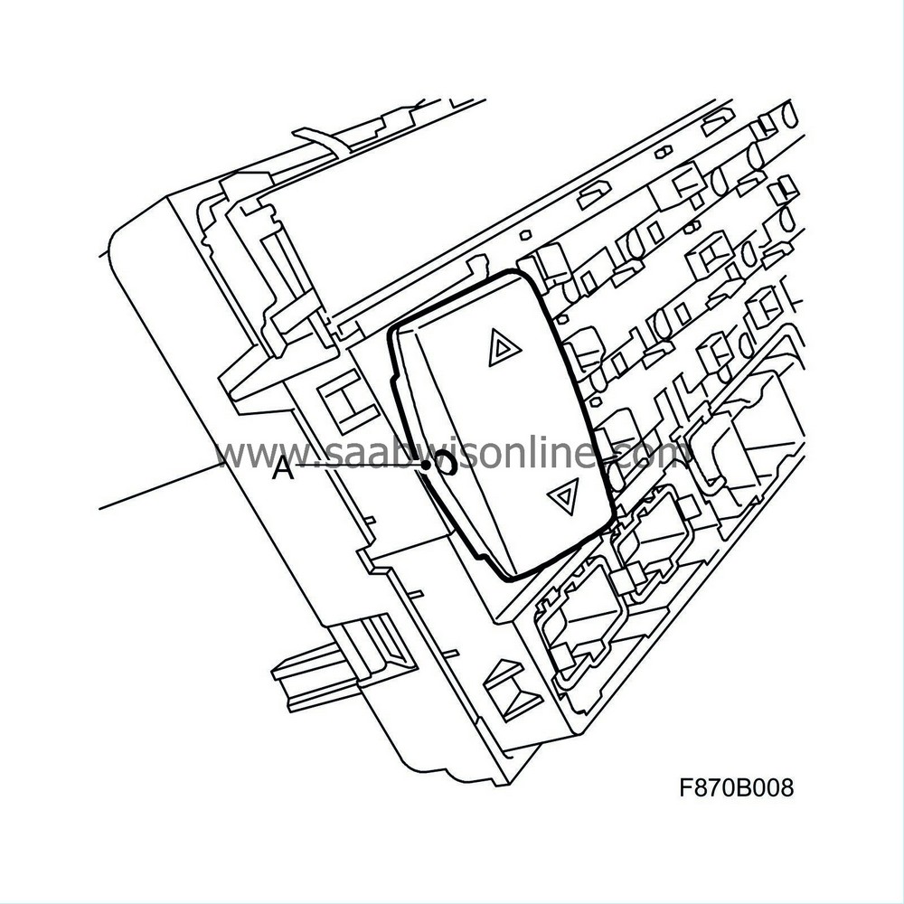
Fit the temperature button as follows:
|
|
|
•
|
Fit the temperature button on the outermost pin (A).
|
|
|
•
|
Push the temperature button inwards towards the centre of the ACC panel (B) and push on (C) the button.

|
|
11.
|
Check the play on the temperature buttons. If there is too much play, remove the temperature button again and bend back the temperature button's mounting (see steps 5 and 6).
|
|
12.
|
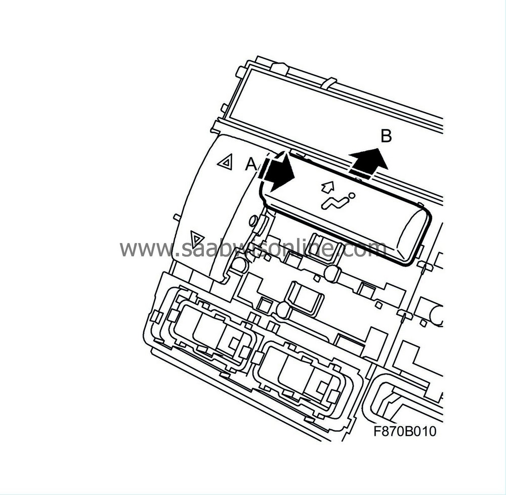
Fit the new spare part buttons on the ACC unit by placing the button 2-3 mm below the original position. Press the button inwards (A) and move the button upwards (B) under the two supports on top of the button.
|
|
13.
|
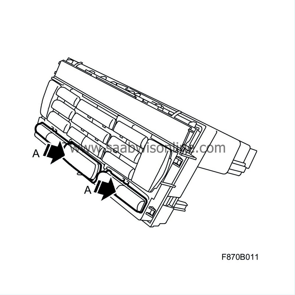
Fit the seat heating buttons, dummy buttons and the button for the hazard flashers. Make sure that the downward facing catches are aligned with the holes and carefully fit the buttons (A).
|
|
14.
|
Place the front panel flat in front of the ACC unit as it is positioned in the car and carefully fit the panel with equal force. Make sure that all the catches mate correctly (A).
|
Note
|
|
If the front panel breaks, replace it with a new panel.
|

|
|
15.
|
Check all the buttons by pressing in the buttons.
|
|
16.
|
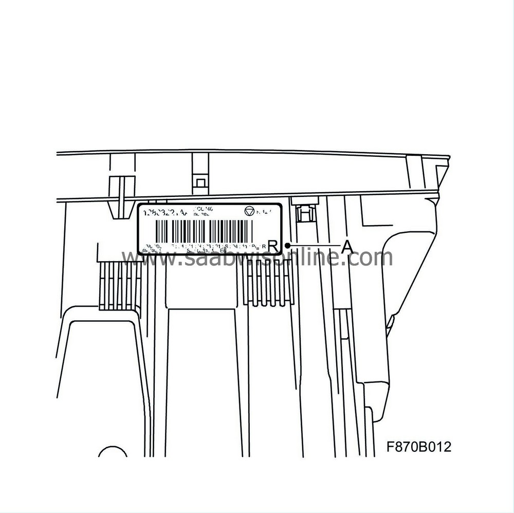
Write the letter R in the right-hand corner of the ACC unit's label (A). Use a permanent black felt-tip pen. The letter must not be written over any other indication on the label.
|
|
17.
|
Fit the ACC panel according to WIS - 9-3 (9440) - 8. Body - Air Condition Control - Automatic climate control - ACC unit (216).
|
|
18.
|
Check the function of the buttons on the ACC unit.
|
|
Warranty/Time Information
|
In the case of customer complaint and if the car is
within the warranty period
, use the following information to fill out the claim:
Failed Object: 87095
Fault/Reason code: 87
Location code: 09 (US=9)
Warranty type (US): 01
Repair/Action code: 01
Labour Operation (US): 8709501
Labour Operation (CA): C2992
Time: 0.4 hr


