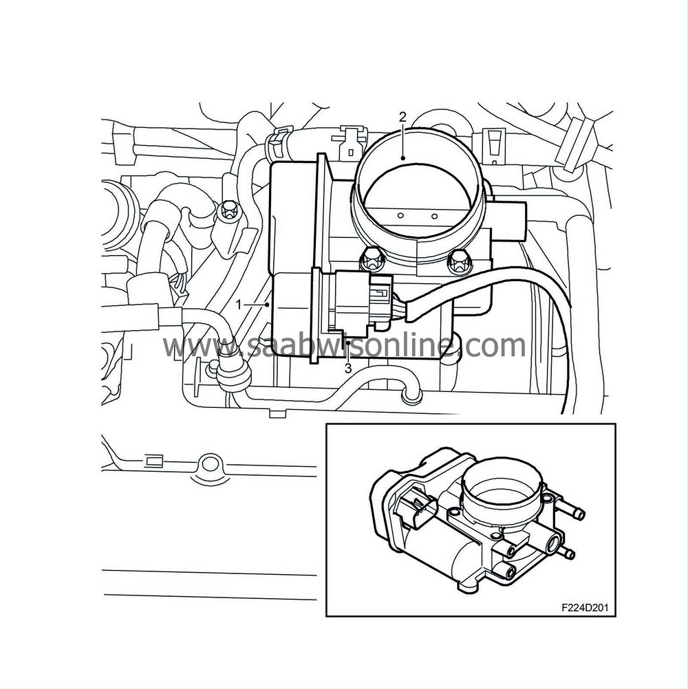
Throttle adjustment
| Throttle adjustment |
| 1. |
Throttle motor
|
|
| 2. |
Throttle disc
|
|
| 3. |
Connector
|
|
The throttle is turned by throttle motor with brushes supplied from the control module pins 13(A), 45(A), 30(A) and 62 (A) with a PWM signal. The spring tries to keep the throttle in its resting position which is slightly open.
The control module can turn the throttle in both directions by reversing the motor polarity. The PWM condition increases, the further the throttle lies from its initial value.
Two throttle sensors are connected to the throttle spindle. The sensors comprise potentiometers powered by 5V from the control module pin 20(A) for sensor 1 and 3(A) for sensor 2, and are grounded from control module pins 58(A) and 42(A).
The voltage from sensor 1 is connected to the control module pin 10(A) and increases with the throttle position.
The voltage from sensor 2 is connected to control module pin 26(A) and reduces with the throttle position. The sum of the two sensor voltages is thus always 5V. The voltage from sensor 1 is used by the control module as a value for the current throttle position.
In case of a serious fall in the throttle control, it will be turned off and the control module will go into limp-home mode. The throttle then goes to his position of rest, which gives the engine a certain throttle area and therefore a certain air mass.
The result from torque control is converted to air mass/combustion. Throttle control converts this to a certain requested value for throttle position sensor 1 and compares the requested value with the actual value for the sensor. The deviation gives rise to a PWM signal to the throttle motor, the size and polarity of which turns the throttle until the requested area is attained. Should a serious fault arise in the throttle control, it will be turned off and the throttle will go to rest position, which is determined by a spring. Now, the engine torque can only be regulated using fuel cut-off and ignition timing.


