Detailed description, Z19DTH
| Detailed description, Z19DTH |
| Pistons |
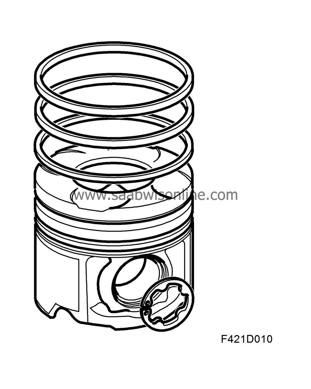
The pistons are manufactured in light alloy and have grooves for two compression rings and one oil scraper ring. The upper compression ring is flat and coated with chromium or molybdenum, while the lower compression ring has oil-scraper properties and is slightly wider than the upper ring. The oil scraper ring is in three pieces. To drain oil from the groove for the oil scraper ring, the piston has drilled holes for the oil to pass to the inside of the piston and drop into the crankcase. The upper piston ring groove has been reinforced with steel inserts.
There is a depression in the piston crown that together with the flat surface of the cylinder head forms the actual combustion chamber. This design means the air attains a very high velocity in the combustion chamber just before the piston reaches top dead centre. This is essential in order to achieve a homogenous mixture of fuel and air. The resulting engine offers high performance with low emissions.
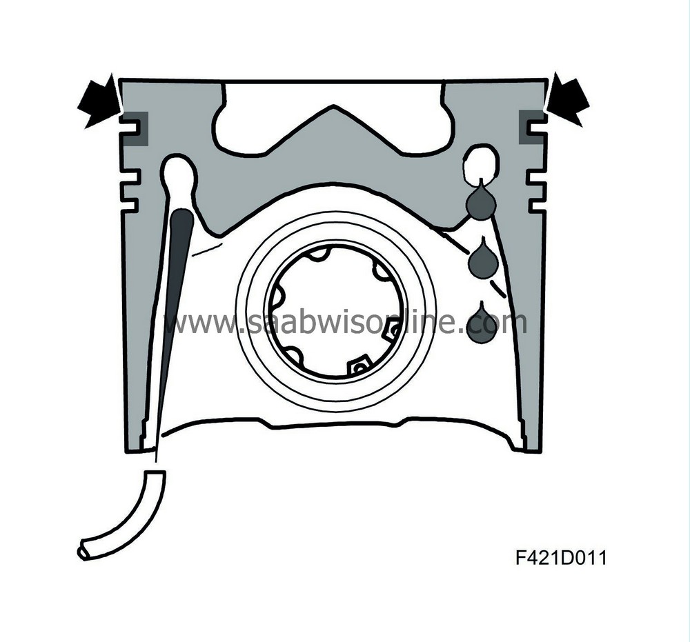
Z19DTH: The pistons have cooling ducts for efficient cooling. Inside the piston is a cooling coil at the same height as the piston ring and there are nozzles in the cylinder block, one for each cylinder. The jet of oil from the nozzle hits a hole leading into the cooling coil. On the other side of the cooling coil is an outlet hole through which the cooling oil passes and drops into the crankcase. This allows a high output without overheating the pistons.
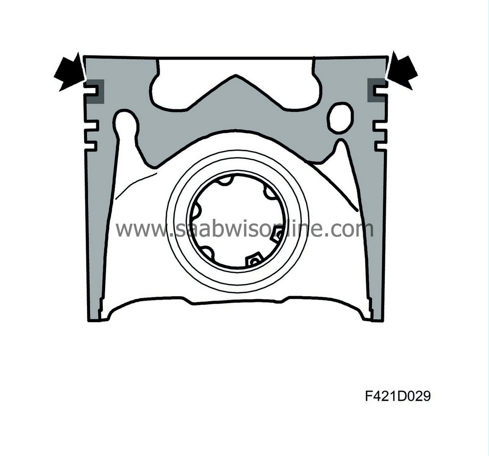
Z19DT: The pistons are oil cooled but do not have the cooling coil. The oil from the cooling nozzle hits the bottom of the piston.
Z19 all: To reduce the friction on the cylinder walls, and consequently the wear, the pistons have been surface treated. The piston skirts are coated with graphite.
The hole for the fully floating gudgeon pin has bearing bushings for increased strength. The gudgeon pin is slightly offset.
The compression ratio is 17.5:1.
| Connecting rods |
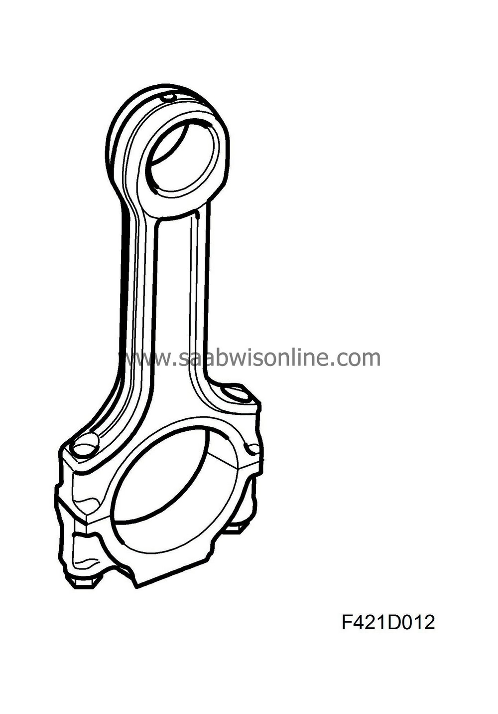
The connecting rods in the Z19DTH are forged and in the Z19DT they are cast. They are fitted with bushings for the gudgeon pins. The gudgeon pin bushing and the bearing shells for the big end bearings are exchangeable. To lubricate the gudgeon pin bushing, there is a hole drilled at the top of the little end.
The gudgeon pin is float fitted in the piston and connecting rod. The movement of the pin is limited axially by circlips fitted in the piston's gudgeon pin hole.
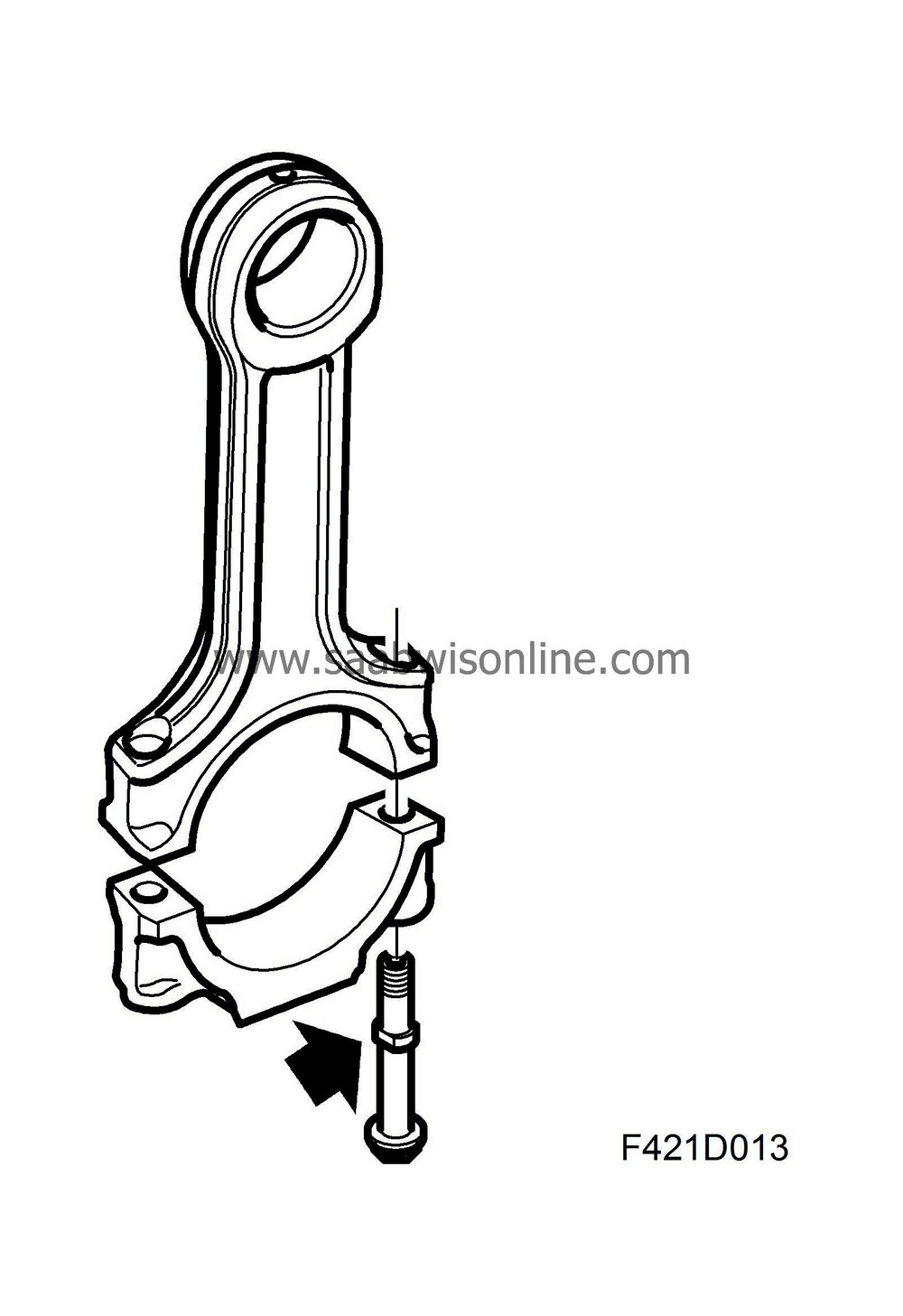
The bearing cap on the big end of the connecting rod has ground surfaces facing the connecting rod. The bolts have collars to guide the bearing cap against the connecting rod.
The engines are fitted with strong connecting rods.
| Crankshaft assembly |
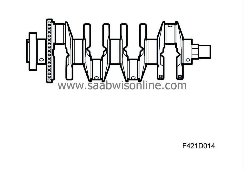
The crankshaft is forged with ground and surface hardened bearing journals. This gives a hard surface to protect against wear. The crankshaft is supported in 5 main bearings, of which the middle one also acts as a thrust bearing. In the shaft are drilled ducts for the lubrication oil. All main bearing shells are exchangeable.
| Cylinder head |
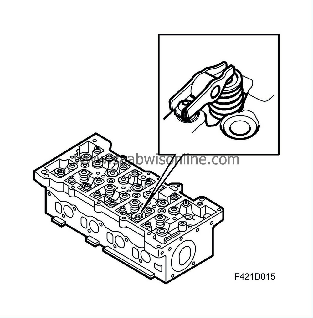
The cylinder head is precision cast in light alloy and bolted on the cylinder block. To provide efficient filling of the cylinders, the cylinder head has 4 valves per cylinder. The injectors are centrally mounted. The two exhaust ducts are identical, while the inlet ducts are designed differently. One duct is used for light engine loads, while the other opens at higher loads via a valve controlled by ECM. This improves the swirling motion. The cylinder head is sealed with a three-ply metal gasket that is available in three thicknesses.
Z19DT: The supply of lubricating oil to the camshaft bearings takes place through a separate steel pipe. The shape of the inlets is designed to give a considerable rotation of the intake air.
| Camshaft housing |
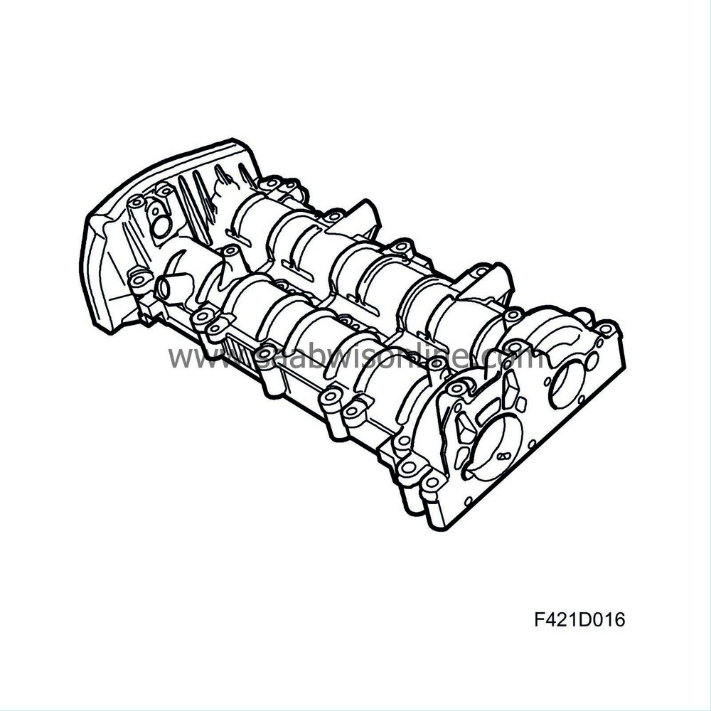
The camshafts are mounted in a housing that also acts as a cover on the cylinder head. In the camshaft housing are two journals with five bearings each. The camshafts are supported directly in the camshaft housing goods. The bearings are force-feed lubricated.
| Intake manifold |
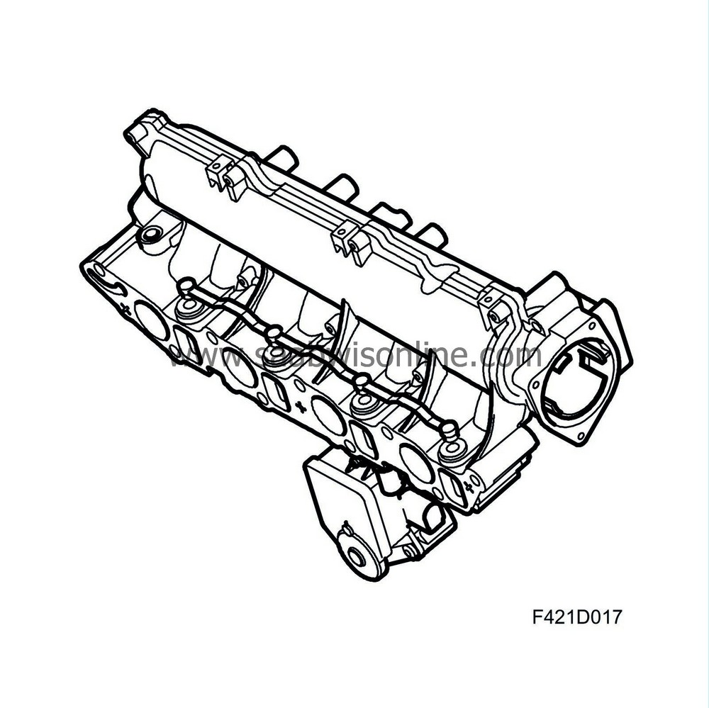
General
The intake manifold is used to distribute air to each cylinder. The throttle body, EGR valve, return fuel collector, swirl valve and actuator motor for the swirl valve are mounted on the intake manifold.The intake manifold comprises a plenum chamber and eight inlet passages to the cylinder head, two for each cylinder. The inlet passages are designed to guide the air from the plenum chamber in the cylinder head inlet ducts. The cylinder head ducts are designed to provide a good filling factor and good swirl and tumble formation. A strong swirl motion is especially advantageous under light engine loads to attain a good mixture of air and injected fuel. One of the inlet ducts to each cylinder is designed to give the air a spiral motion as it passes into the cylinder. The shape of the other duct means the air enters at a steeper angle and with less spiral, called tumble. In order to obtain this form of tumble for every possible operating condition, the engine intake manifold has a throttle valve in each tumble duct operated by an actuator motor.
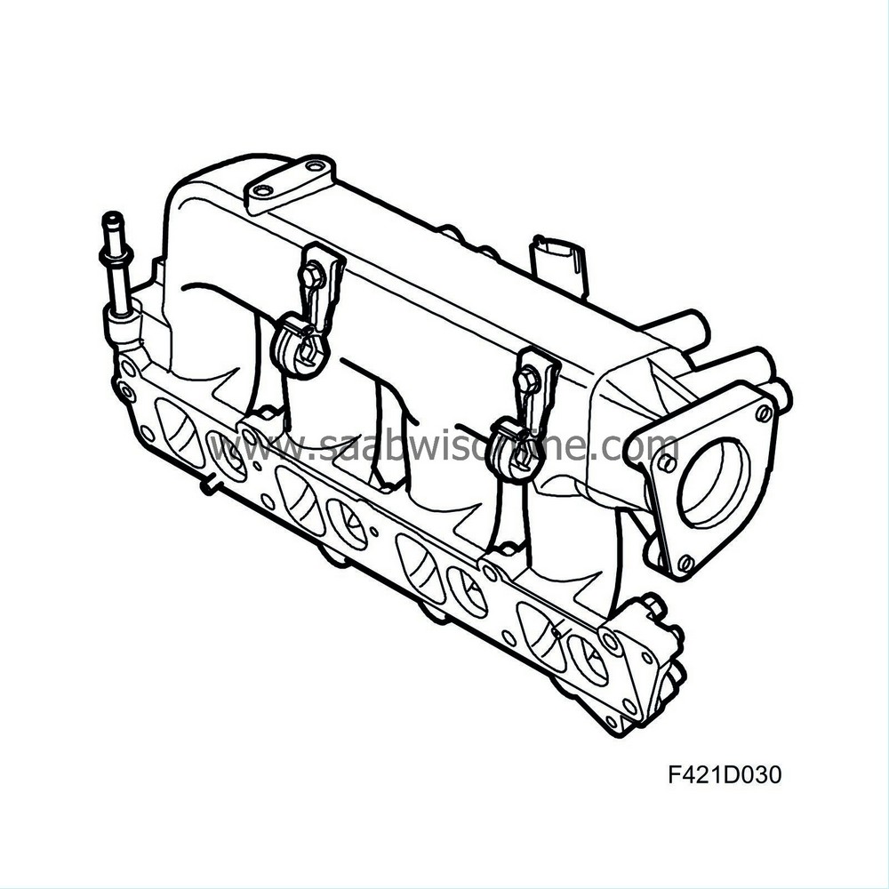
Z19DT does not have a swirl valve.
Function for light load, low to medium rpm
For driving under light loads, a strong turbulence is aspired to during the induction stroke in order to ensure a good mixture of air and fuel. This is difficult to achieve, however, as the mass air flow through the engine at this stage is only moderate. The solution is to increase the swirl action through external influence. By allowing the air to flow in only through the inlet duct giving the strongest swirl and blocking the other, a strong turbulence can be achieved also in this case. The tumble inlet duct is now blocked by the valve. Somewhat misleadingly, these valves are called "swirl valves" despite being situated in the tumble duct.Function for high load, medium to high rpm
When driving with high output, the restriction of intake air would be too great if only one inlet duct was open. Therefore, the swirl valve will open so that the cylinder is supplied with air from both inlet ducts. The result is a considerable increase in fill factor of the cylinder so that the ECM can add more fuel without increasing emissions. The swirl throttle can be opened continuously so that the balance of tumble and swirl can also be controlled continuously. This is to obtain as good a mixture of fuel and air as possible.| Camshaft drive |
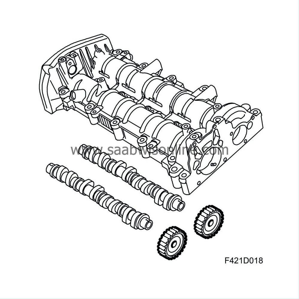
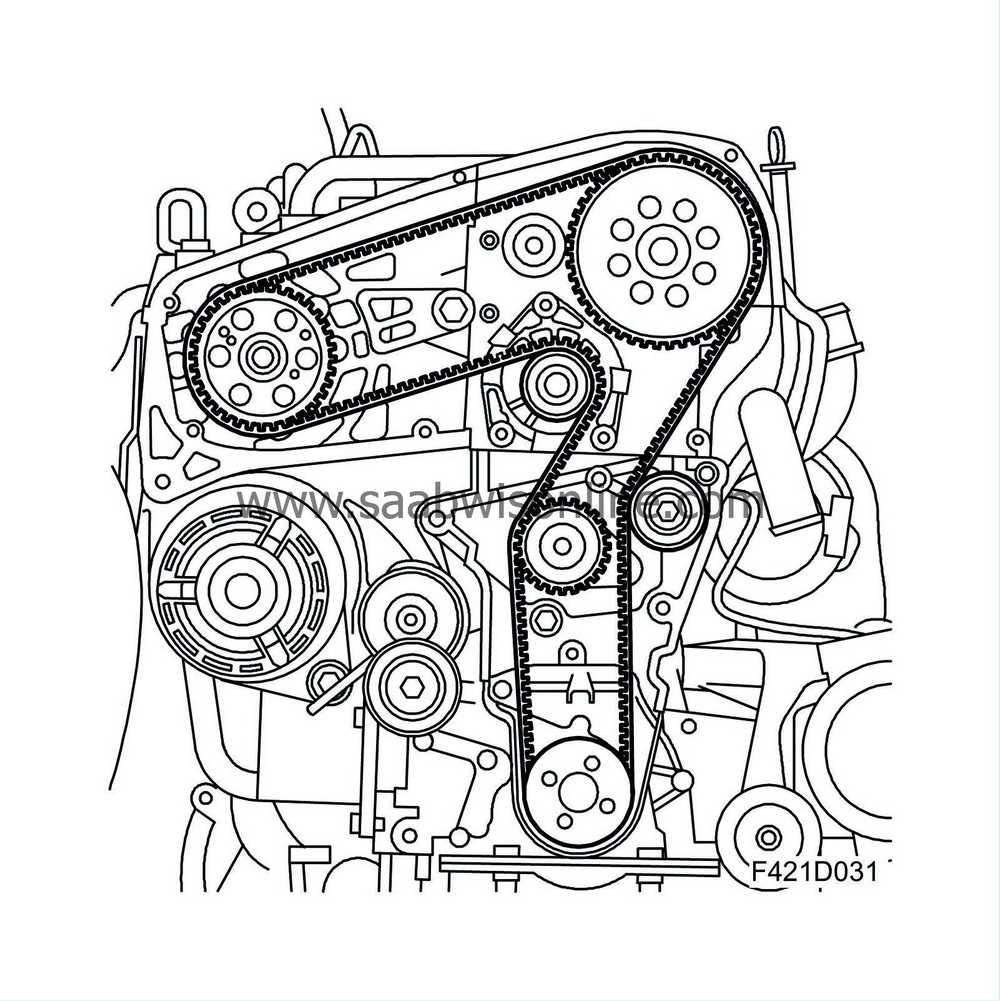
Camshafts
Z19DTH: The engine has twin overhead camshafts with the exhaust camshaft driven by a belt with self-adjusting tensioner. On the exhaust camshaft there is a pinion that drives the intake camshaft. The camshafts act on rocker arms via a roller bearing mounted on the rocker arm. The need for valve adjustment is eliminated as this is done continuously via hydraulic equalisers under the valve rocker.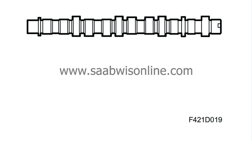
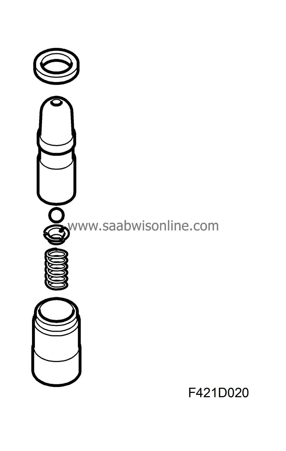
The valve clearance balancer works in an oil bath and is provided with oil via an oilway in the cylinder head. The main advantages are low friction, quiet running and high reliability. The vacuum pump is driven directly from the exhaust camshaft.
Z19DT: The engine has a camshaft driven by a belt with self-adjusting belt tensioner. The cam lobes act on valve tappets that have shims for adjusting the valve clearance.
| Lubricating system |
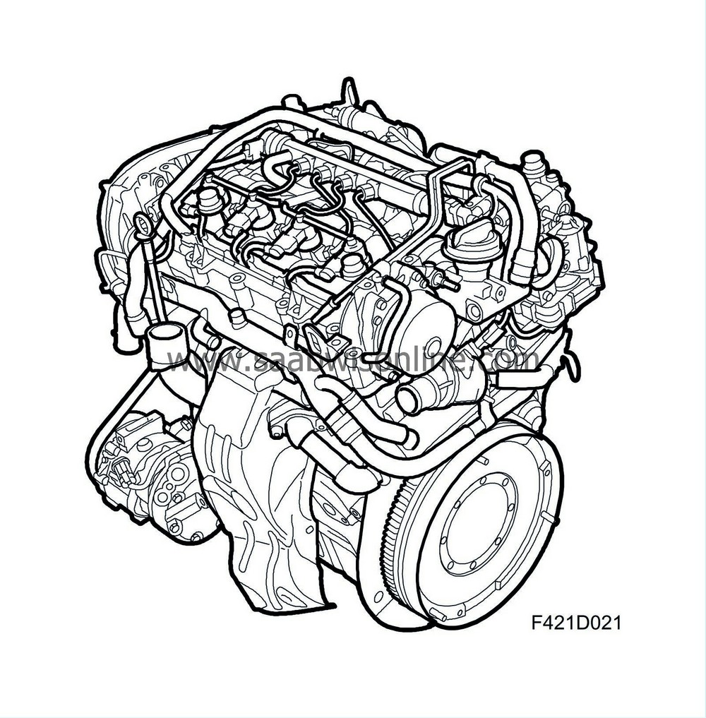
Engine lubrication is through a force feed lubrication system. A filter cleans the oil and the engine has a heat exchanger so that the engine oil can attain a suitable temperature. The heat exchanger is coupled to the engine cooling system.
Oil sump
The oil sump is cast in aluminium alloy in a sturdy design to reduce noise. It has a baffle plate to reduce the risk of oil splashing onto the crankshaft and the oil pump running dry.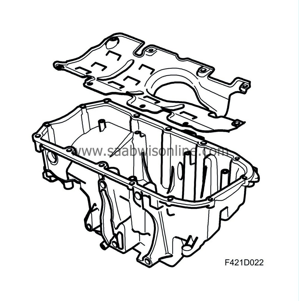
Oil pump
Engine lubrication is by means of a force feed lubricating system in which the oil pressure is created in a gear pump comprising a pump housing and a gear ring with offset centre. The pump is mounted on the camshaft drive end of the engine and is driven directly from the crankshaft. The pressure reducing valve is located in the pump housing. The oil pump draws oil from the oil sump via a pipe into the gear pump itself from where it is forced into a duct in the engine to the heat exchanger. The oil is filtered in the oil filter once the oil has passed the heat exchanger.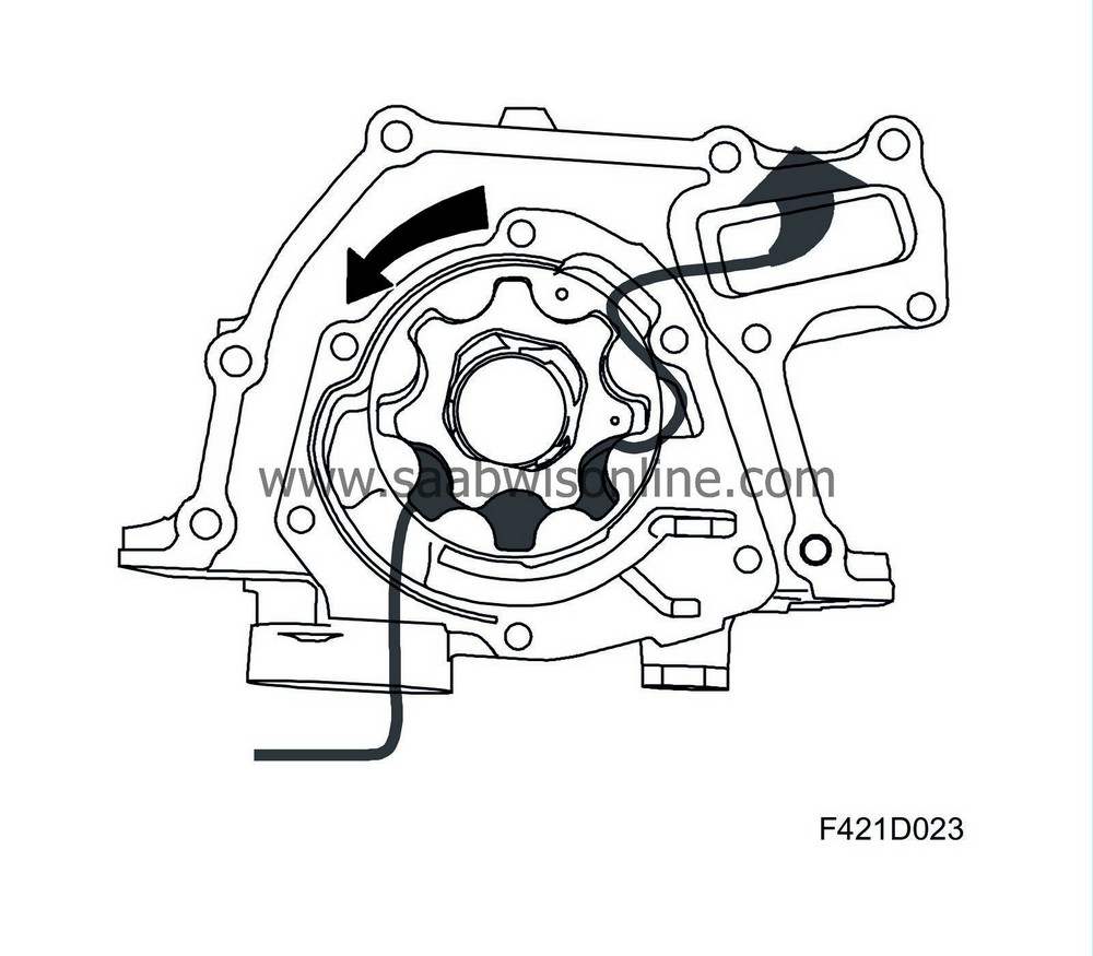
Oil filter
The engine has an oil filter of cartridge insert type to prevent wear and engine damage caused by particles and to reduce engine wear. The filter cartridge must be changed according to the service schedule. In case of blockage in the filter so that the oil has difficulty passing, an overflow valve will open in the oil filter holder cap. Oil can then pass without being cleaned. This is an "emergency function" to ensure the circulation of oil under all circumstances.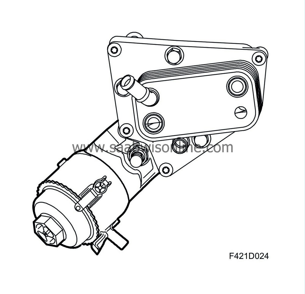
Heat exchanger
In order for the engine oil to maintain an even temperature, it passes through a heat exchanger. When the engine is started cold, the engine coolant will heat the engine oil. The opposite applies when the engine is driven under high load, i.e. the engine oil is warmer than the coolant, when the heat exchanger will cool the engine oil. The heat exchanger is mounted on the cylinder block on the back of the engine together with the oil filter.| Drive for auxiliaries |
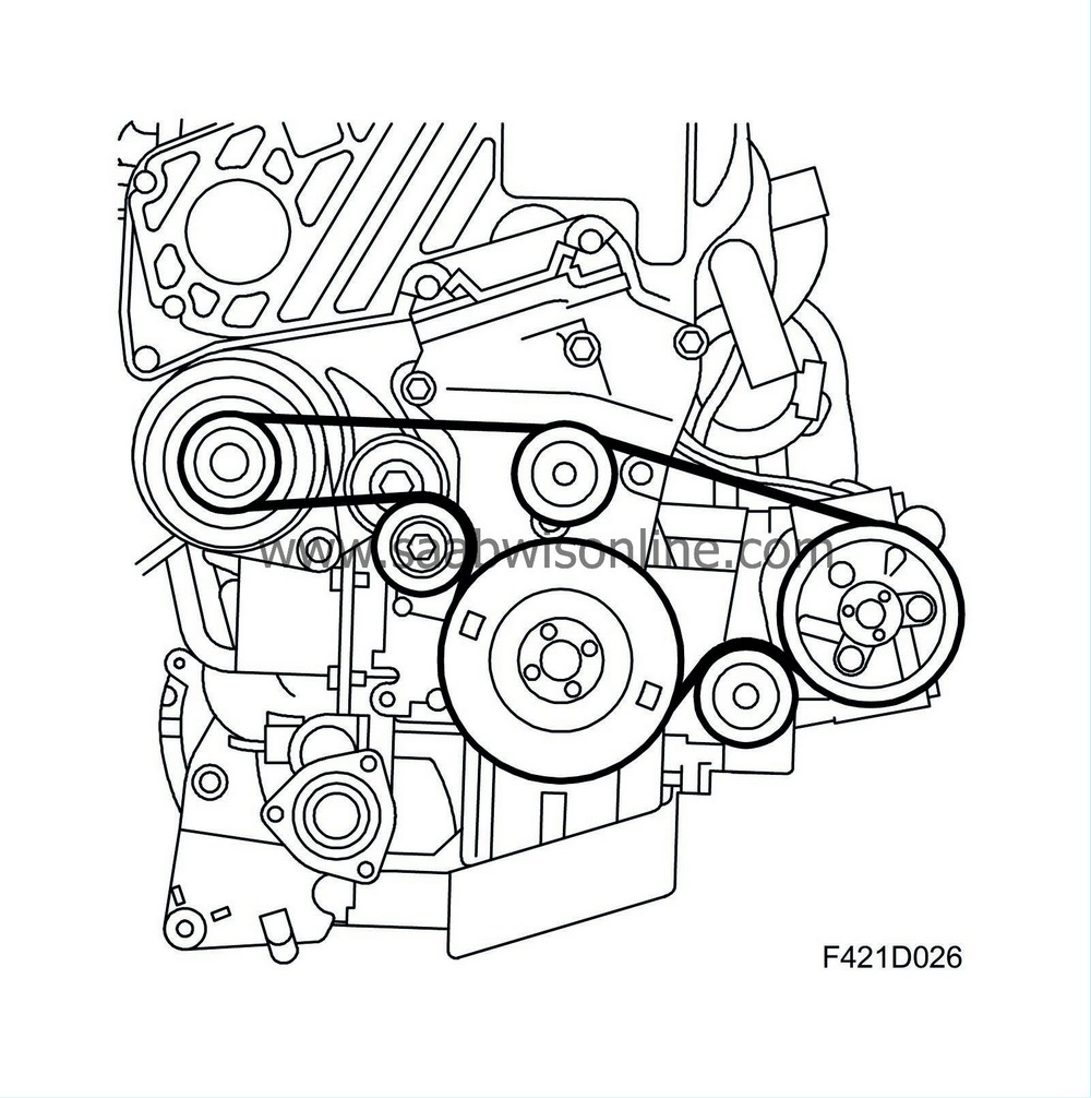
The engine has a belt circuit for driving the auxiliaries. The belt tensioner is automatic and self-adjusting.
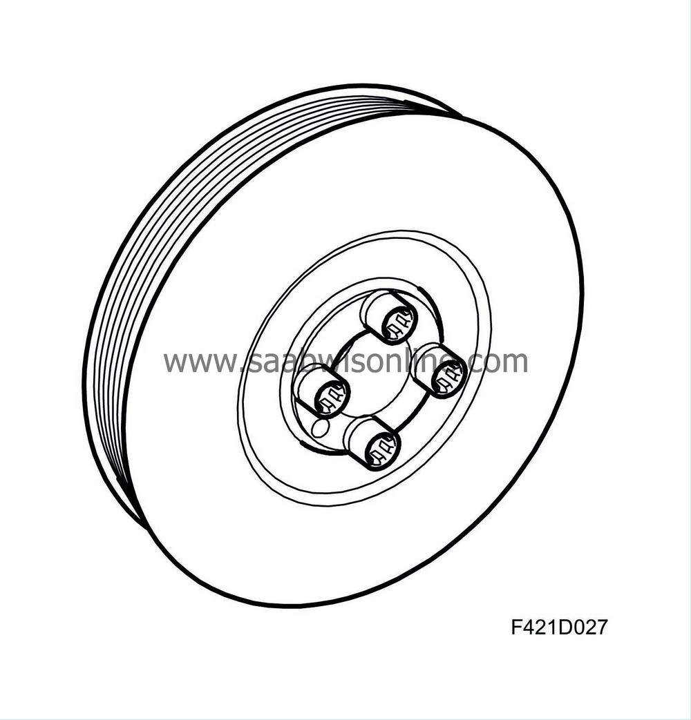
The crankshaft pulley is fitted with resonant vibration dampers to dampen the resonance of the crankshaft (torsional vibration) and in the circuit for the auxiliaries. To further improve the properties of the belt circuit, the alternator belt pulley is freewheel type. The following units are driven by the multigroove belt:
- A/C compressor
- Alternator


