Detailed description
| Detailed description |
| Catalytic converters |
A combination of two catalytic converters is used to clean the exhaust gas. These can oxidise hydrocarbons (HC) and carbon monoxide (CO) to carbon dioxide (CO 2 ) and water (H 2 O). The catalytic converter system comprises a front catalytic converter and one that is integrated with the particle trap.
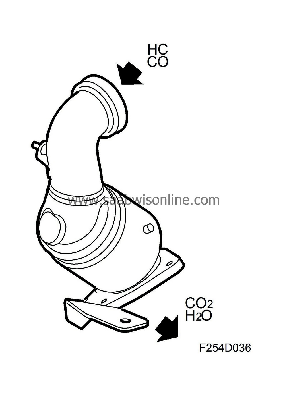
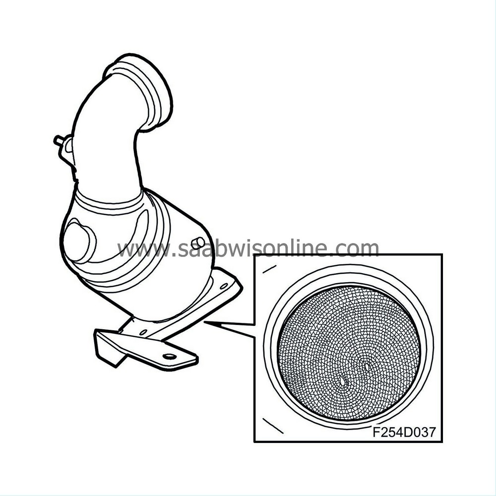
Integrated in the particle trap is the rear catalytic converter mounted in front of the particle trap. Unlike the front catalytic converter, the rear one has a ceramic monolith (carrier). The monolith is coated in platinum (Pt). The use of diesel fuel with high sulphur content will contaminate the catalytic converters.
| Particle trap |
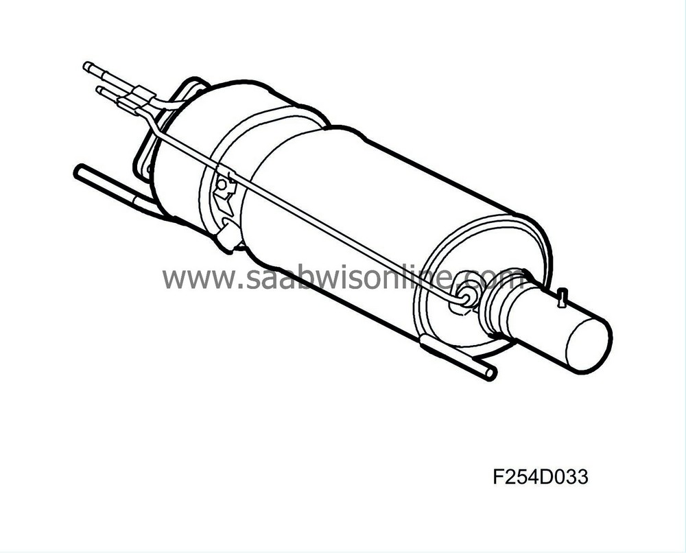
The particle trap functions as a soot trap, when the trap is full the soot is combusted. This is called regeneration.
Construction
The particle trap comprises a porous body, similar to a catalytic converter with many small passages with porous walls.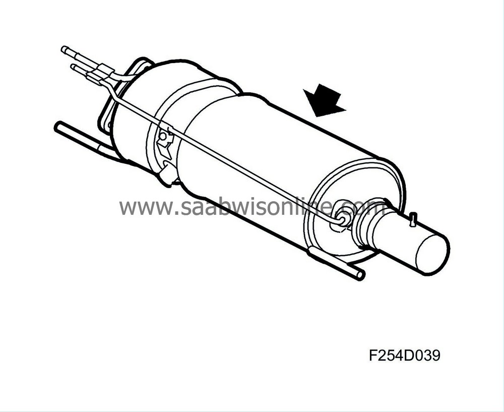
Every other passage is blocked at the back (inlet passage) and every other at the front (outlet passage).
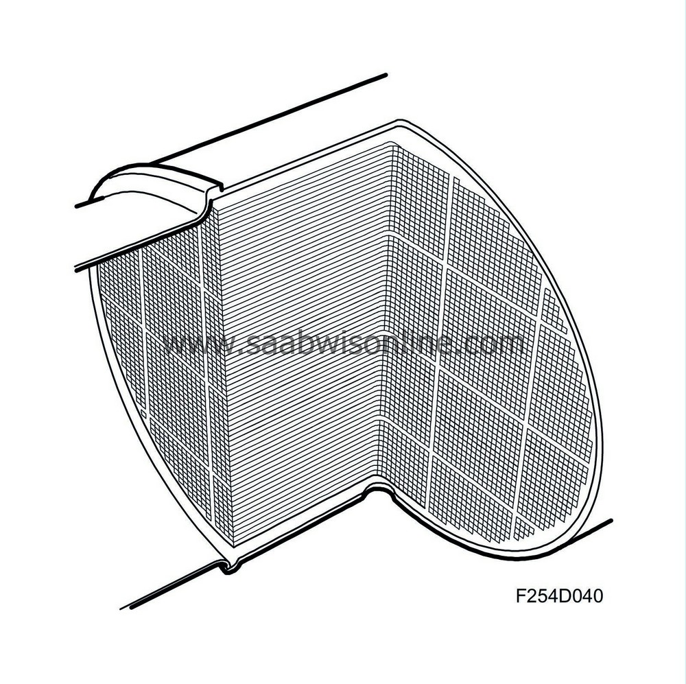
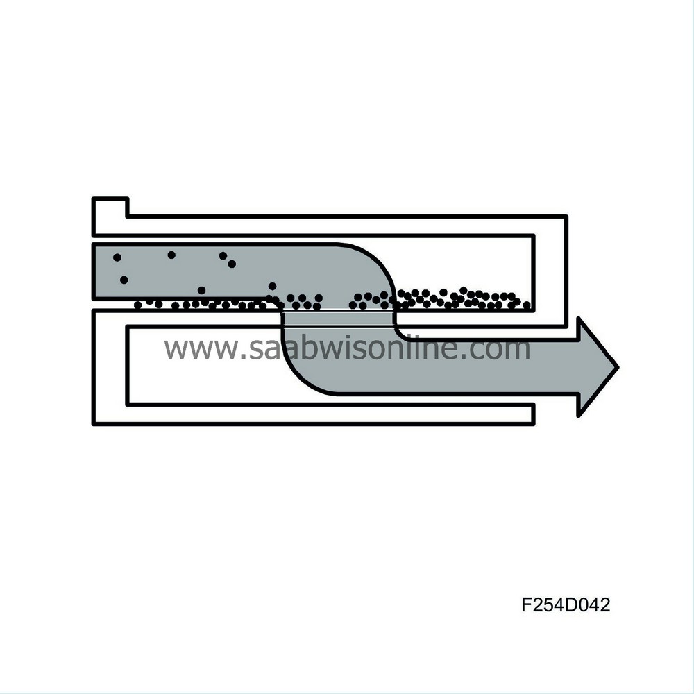
The exhaust gas is forced to flow into a passage that is blocked at the rear (inlet passage).
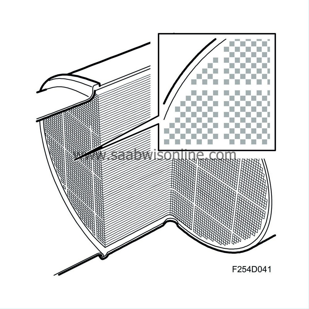
This passage is surrounded by outlet passages. The exhaust gas in the inlet passage will pass through the porous walls while the particles of soot are too large to pass through and will stick inside the particle trap.
Soot calculation
ECM calculates the amount of soot in the particle trap. Note that the differential pressure sensor (744) is not used to measure whether the trap is full but for diagnosis purposes and to prevent manual regeneration using the diagnostic tool if the particle trap is too full. The calculated amount of soot is based mainly on engine load and speed.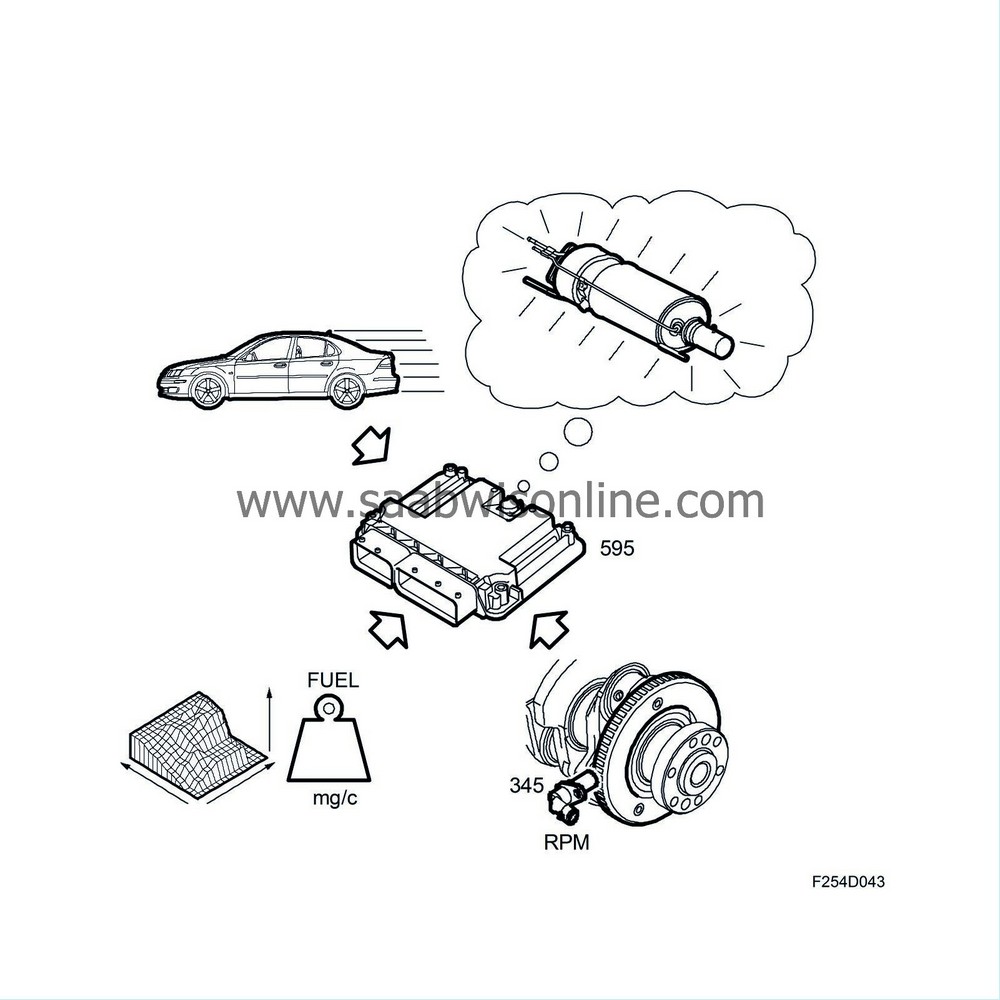
Automatic regeneration
ECM monitors driving style and selects a suitable time to employ regeneration. Cars driven a lot at idling speed and low load will attempt to regenerate earlier than cars driven more with high loads and engine speeds. In order for regeneration to take place, a certain temperature must be attained in the particle trap so that the soot can be burned. A temperature above +550°C (1022 F) is required in the particle trap if the soot is to be burned. A particle trap exhaust temperature sensor (602R) is used to measure the temperature. If the temperature cannot be attained, ECM assumes regeneration is not possible and will make a new attempt at the next opportunity.To increase the temperature in the particle trap so that regeneration will take place, an extra injection is performed during the exhaust stroke. At around 160° after top dead centre, TDC, a small amount of fuel is injected into the cylinder and as this is so late (the piston is almost at bottom dead centre, BDC, with the exhaust valve open) the extra fuel will not contribute to the engine torque, nor will the exhaust temperature increase appreciably. Quite simply, the exhaust gas is enriched with HC (hydrocarbon), which initiates a reaction in the front catalytic converter. The gas temperature increases, which is monitored by the front exhaust temperature sensor (602F). The heated exhaust passes into the particle trap where it reaches the rear catalytic converter first and is further heated to at least +550°C (1022 F), the temperature required for regeneration, or the soot will not be burned.
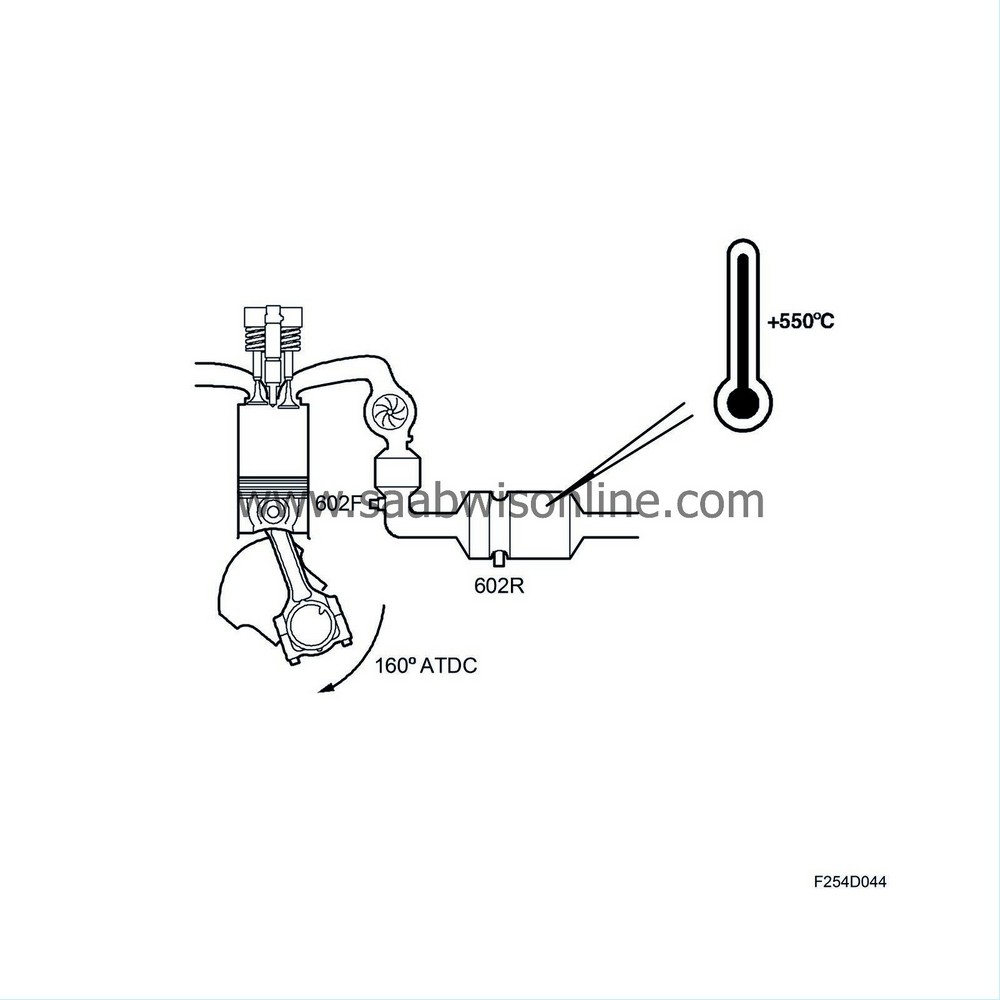
Regeneration continues until ECM calculates that all the soot has been burned. This calculation is based on the value from the exhaust temperature sensor, the engine load and the engine speed. Regeneration can take up to 15 minutes but the driver will not notice any difference in the engine or performance.
In the event of the car being driven in such a way that regeneration is not possible, a diagnostic trouble code will eventually be registered and the "Check Engine" indicator come on. Regeneration must now be done manually using the diagnostic tool.
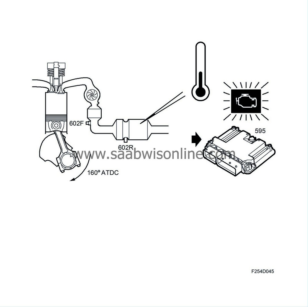
Manual regeneration
Regeneration is not possible in certain driving conditions, e.g. driving under extremely light loads and extensive idling. This will cause a DTC to be generated and the "Check Engine" indicator to come on. Regeneration must now take place manually using the diagnostic tool.Regeneration must be done manually using the diagnostic tool whenever the ECM is changed, see Manual regeneration .
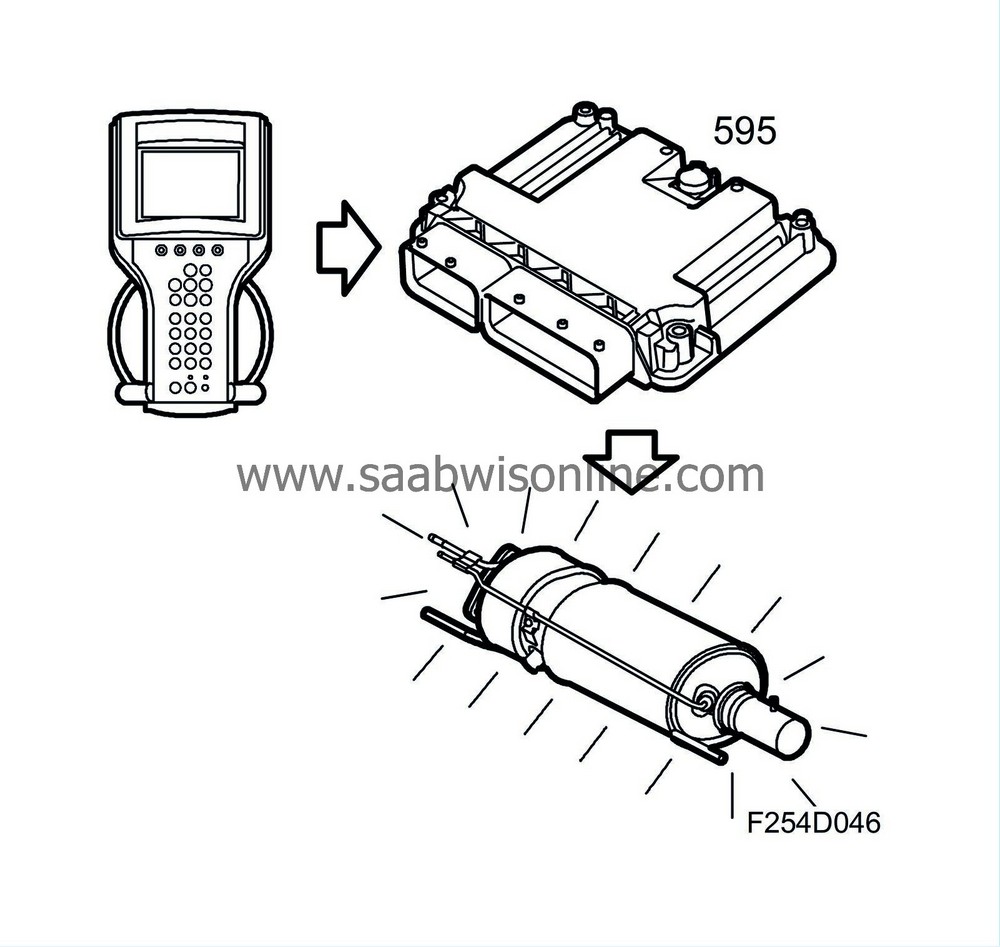
|
|||||||||||||
| Crankcase ventilation, Z19DTH |
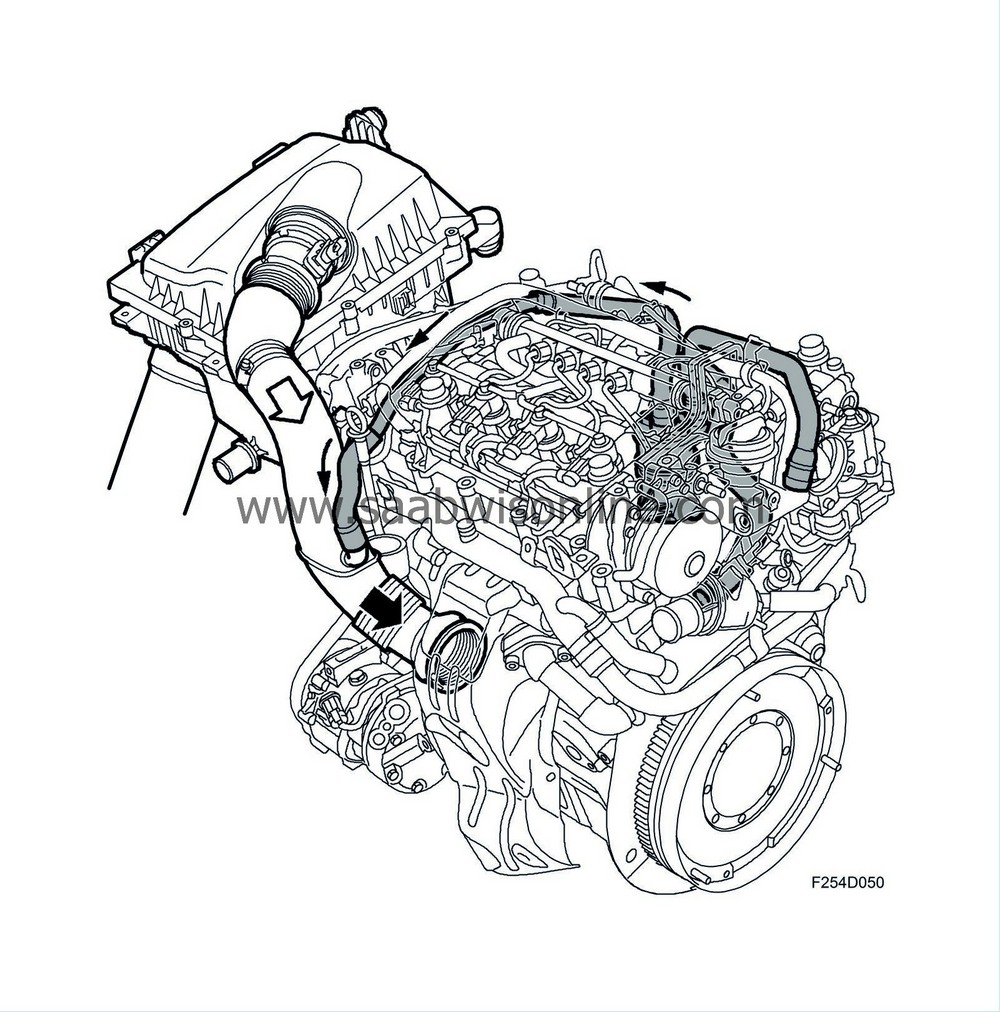
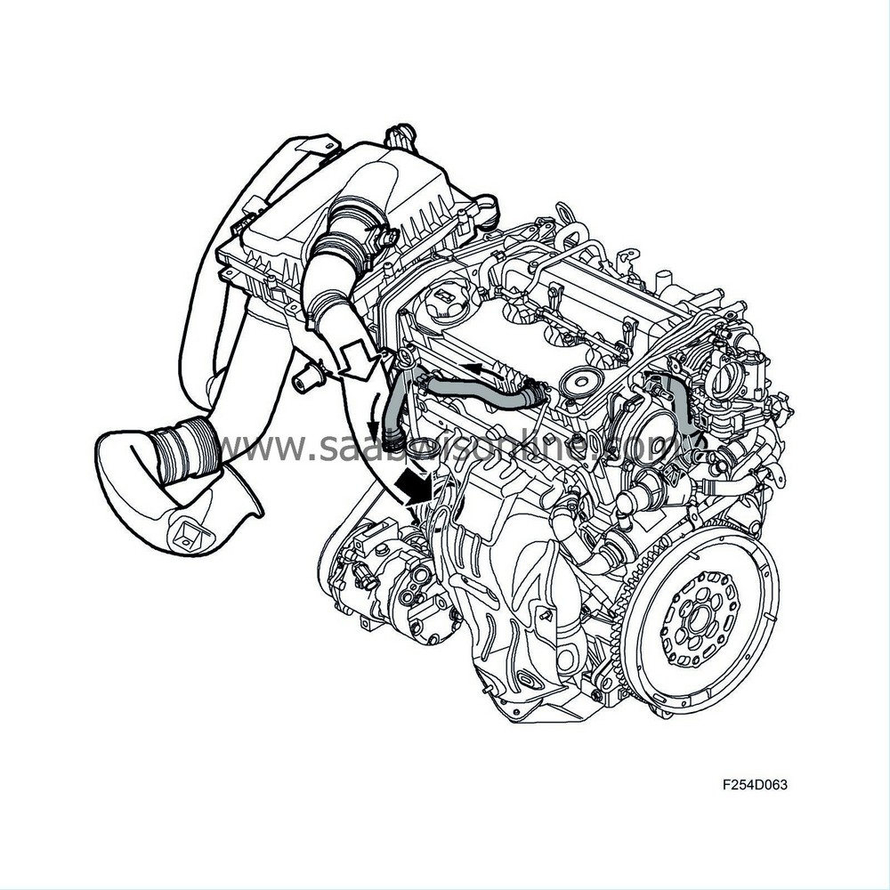
Crankcase ventilation is a completely closed system comprising a nipple on the oil filler and a nipple in the engine block connected to the crankcase and cylinder head. A hose leads from each nipple and are joined together just before the oil trap. A hose runs from the oil trap to the intake manifold between the mass air flow sensor and the turbocharger. Mounted in the bottom part of the oil trap is a return oil hose leading to the oil sump.
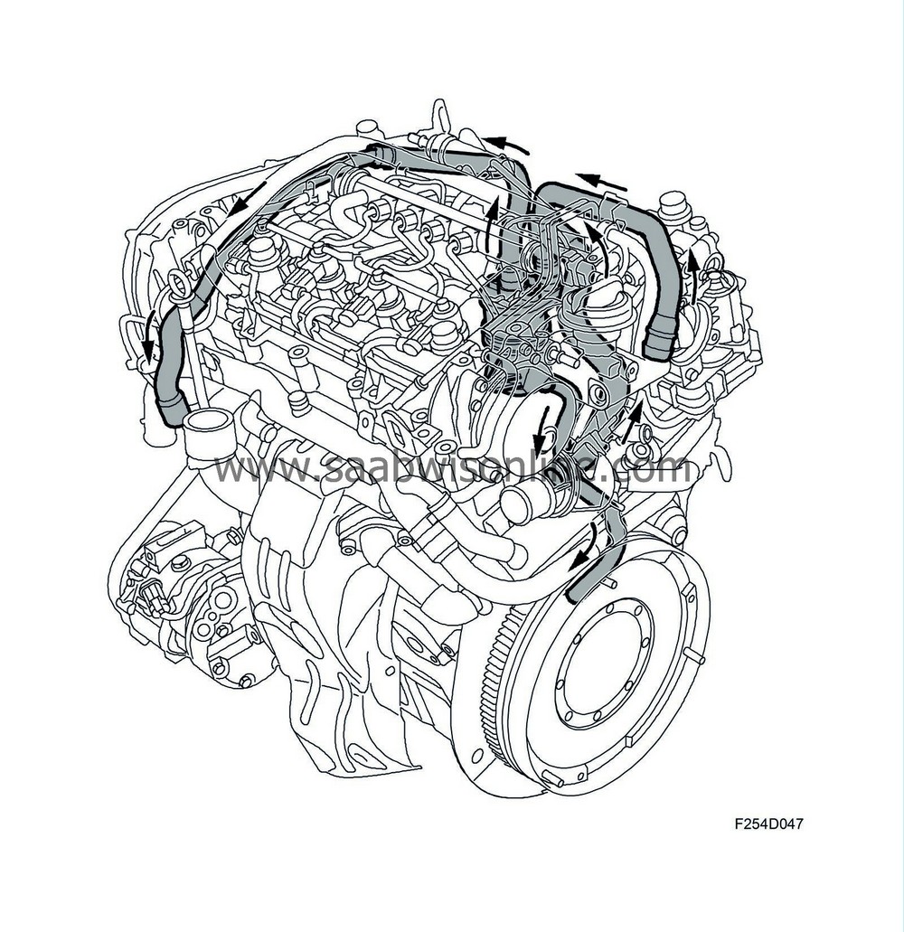
Crankcase gas entering the oil trap is made to rotate by the shape of the cover on the oil trap so that heavier oil particles tend to deposit on the inside of the oil trap.
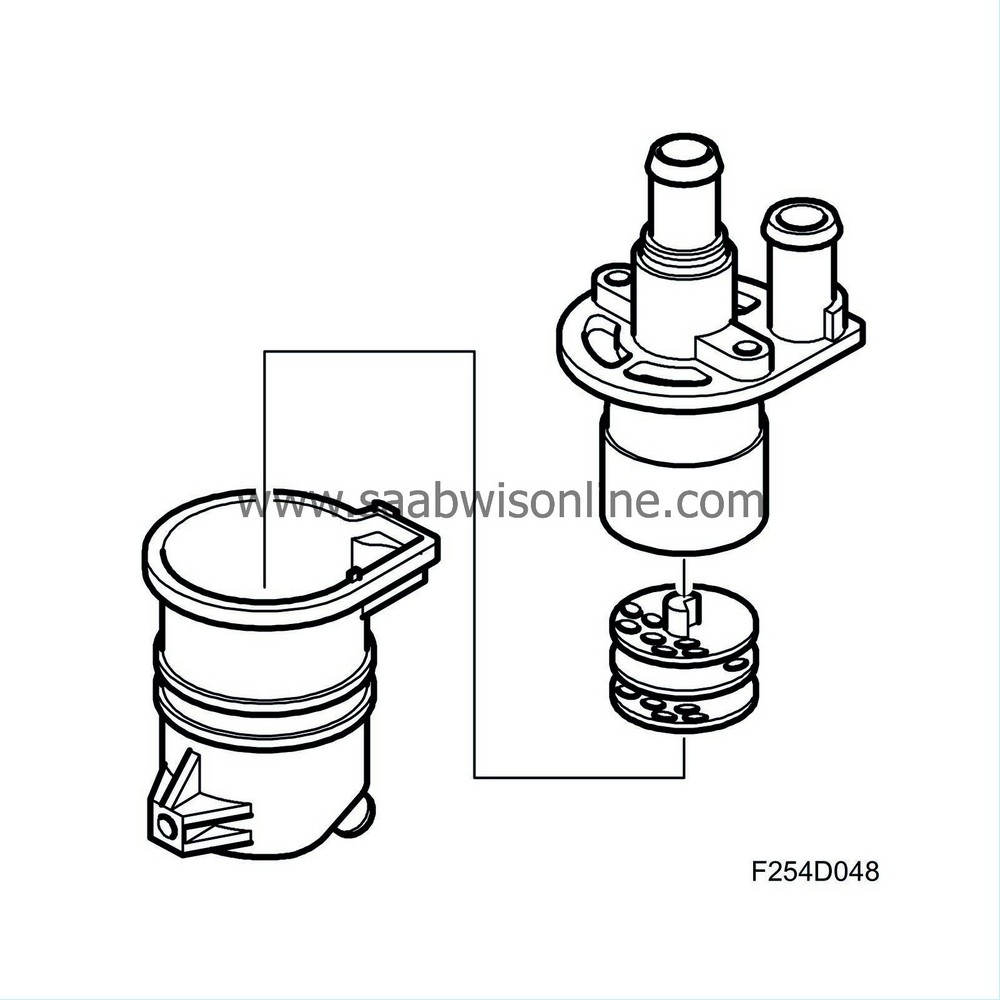
In the middle of the oil trap are three perforated discs with holes that are offset so that the gas is forced to change direction several times. More oil is separated here. There is a cover over the discs.
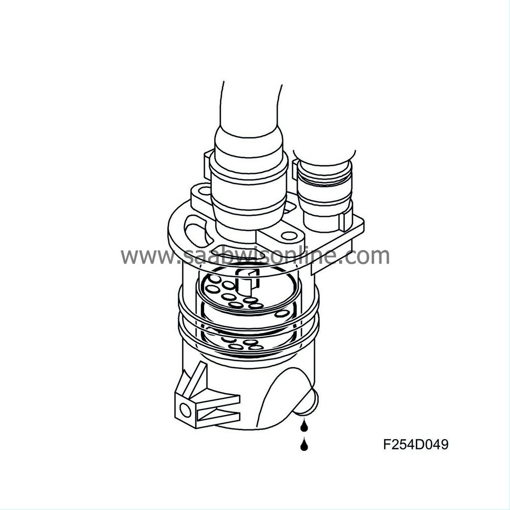
The direction of the gas is down and up. After passing this last step of the oil separation process, the crankcase gas passes via a nipple in the oil trap to the turbocharger inlet, where it is mixed with intake air and then burned in the engine.
| Crankcase ventilation, Z19DT |
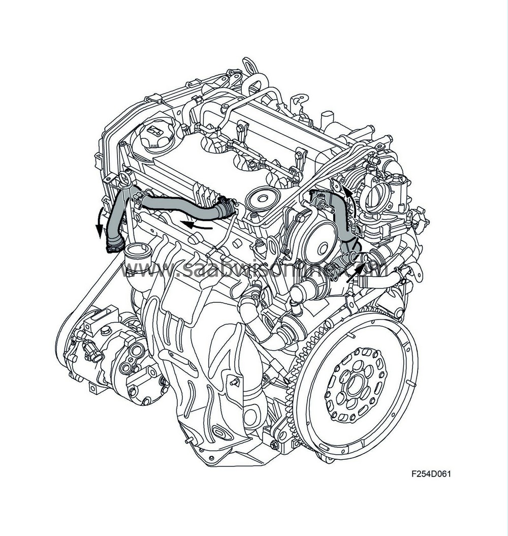
The engine's crankcase ventilation is fully closed. The ventilation comprises an oil trap integrated in the camshaft cover and a nipple in the engine block that is connected to the crankcase. From the nipple in the engine block there is a hose leading to the oil trap. In the camshaft cover is a connection to the oil trap for ventilating the cylinder head. Drops of oil from the crankcase gases are separated in the oil trap. From the oil trap there is a hose connected to the inlet pipe between the mass air flow sensor and the turbocharger.
| Exhaust gas recirculation, EGR |
There are no completely efficient catalytic conversion techniques available today for reducing NOx emissions in a diesel engine, which works with excess air in combustion. This means that emissions must be limited.
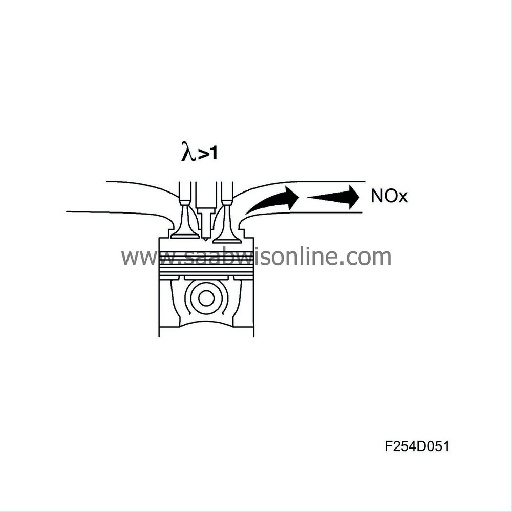
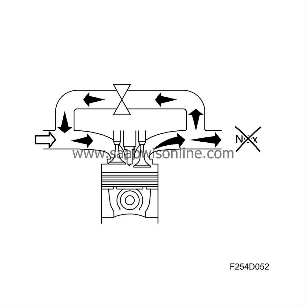
With an Exhaust Gas Recirculation (EGR) system, a controlled amount of exhaust gas is led to the induction side and mixed with the induction air. The result is slower combustion at a lower temperature and maximum pressure, which in turn reduces the formation of NOx.
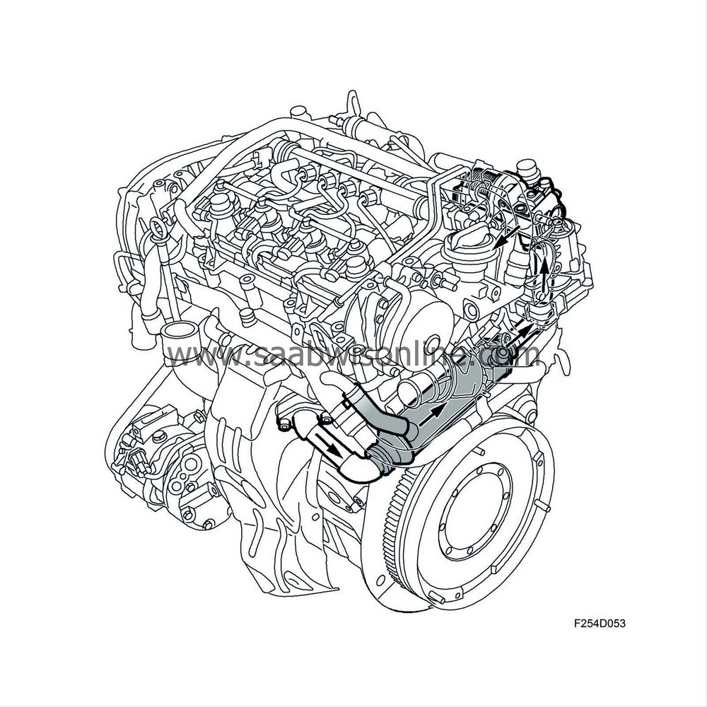
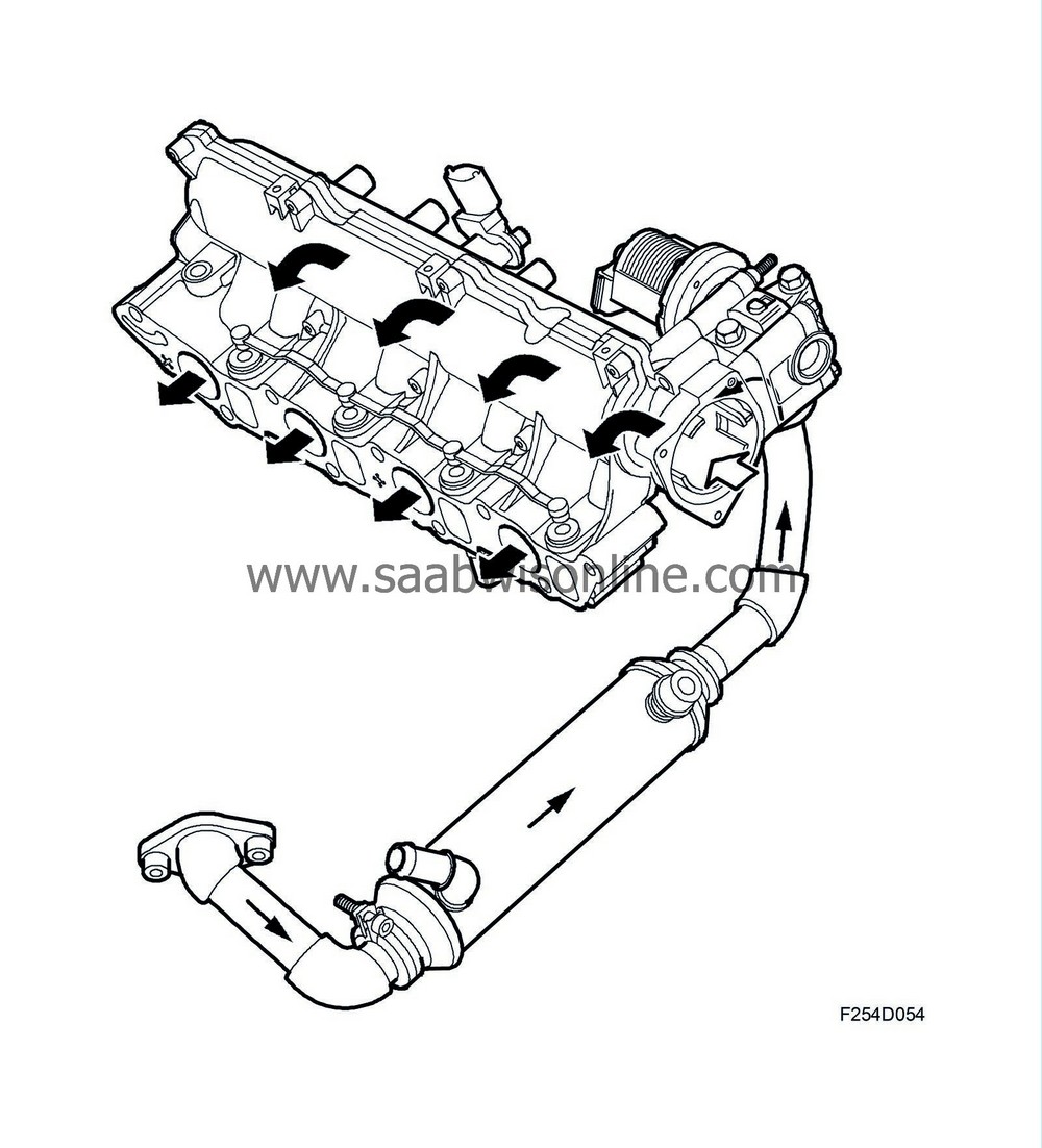
There is a pipe connected on the exhaust pipe which leads exhaust gases to the EGR cooler. This is the type where the exhaust gases pass through a number of tubes. The outside of the tubes is surrounded by the engine's coolant which absorbs heat from the exhaust gases. This way the exhaust gases take less space as they are cooled down. A larger mass of exhaust can pass through one and the same opening.
16V:
8V:
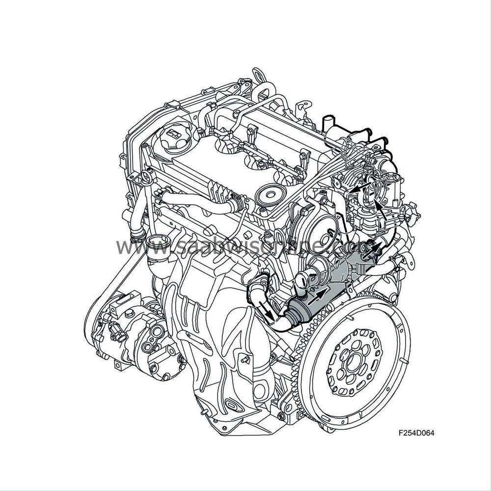
The cooled exhaust goes via a pipe to the EGR valve (606) located on the engine intake manifold. The EGR valve is controlled by ECM, which calculates the requisite amount of EGR for each particular driving condition.
The EGR valve is controlled electronically by ECM and also provides information to ECM on its actual position.
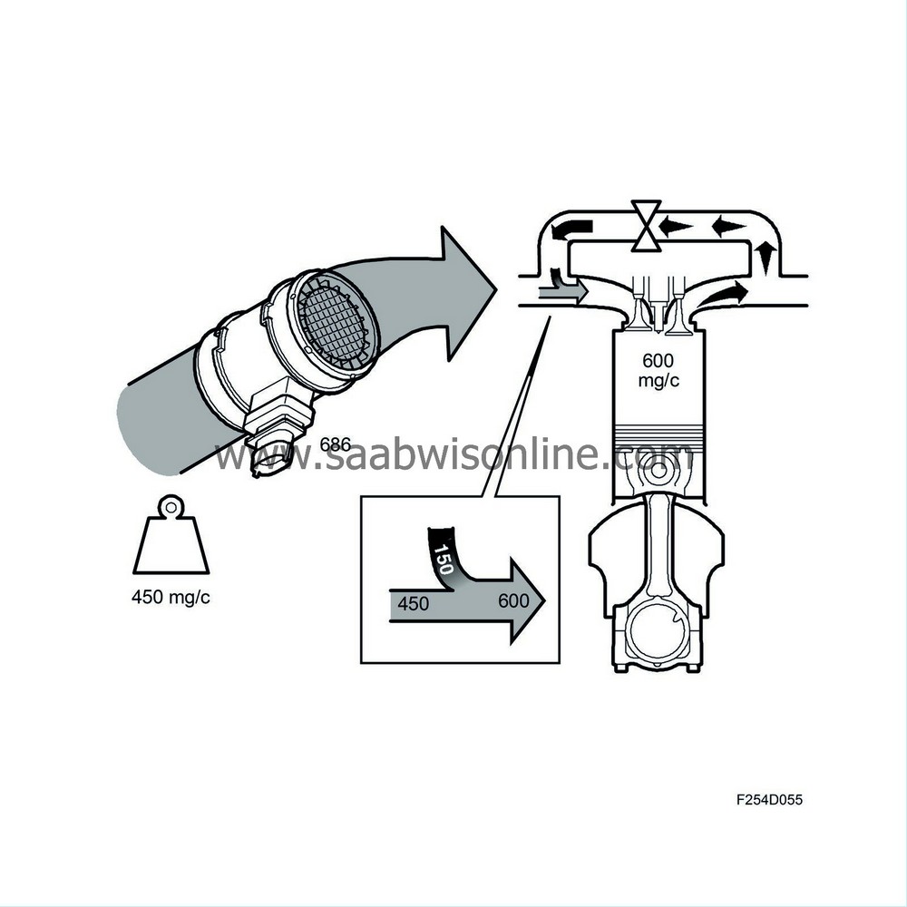
Note that there is no sensor to measure the actual EGR flow, so it is calculated as follows instead:
ECM contains a matrix that describes how much air the engine can pump in a given driving situation. Say this calculation gives 600 mg air per combustion (mg/c). ECM also calculates the amount of fresh air that should be available on this occasion, say 450 mg/c. The difference, 150 mg/c, should be the proportion of EGR gas. ECM will open the EGR valve so that the value from the mass air flow sensor indicates that 450 mg/c air passes into the engine.

 Warning

