Detailed description, fuel system
| Detailed description, fuel system |
| Fuel tank |
The fuel tank is made of plastic and holds 58-litres. The feed pump is integrated in the fuel tank and there is an electric feed pump in the fuel tank that supplies fuel to the high pressure pump.
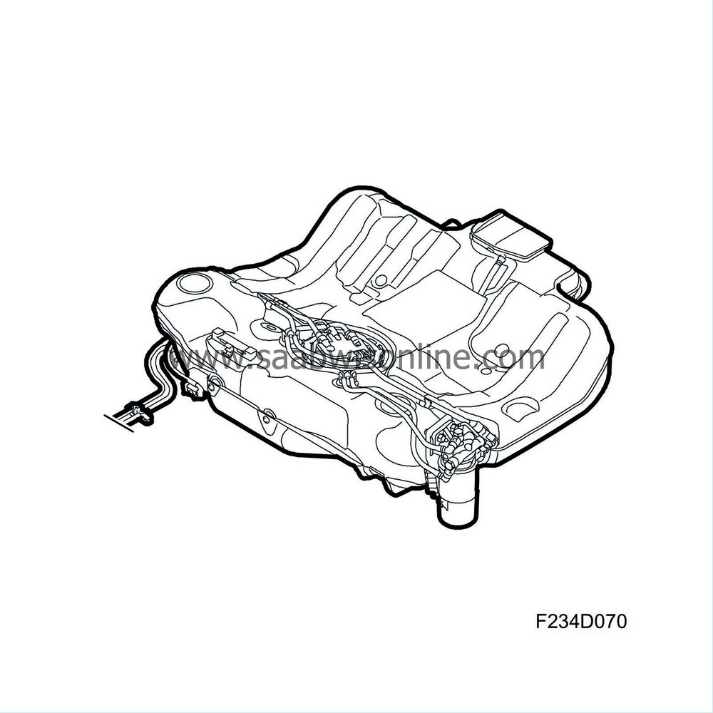
| Feed pump integrated in fuel tank |
An electric feed pump is mounted in the fuel tank that supplies fuel to the high pressure pump. The fuel pressure is 4 bar.
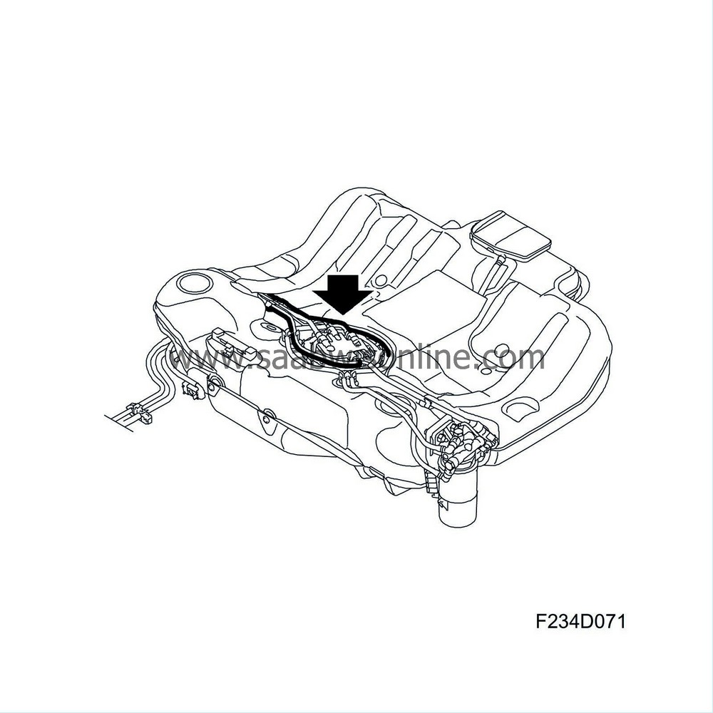
| Fuel lines |
The delivery line is for supplying fuel to the high-pressure pump and the return line for the return fuel. Both lines are made of plastic and steel.
| Fuel filter |
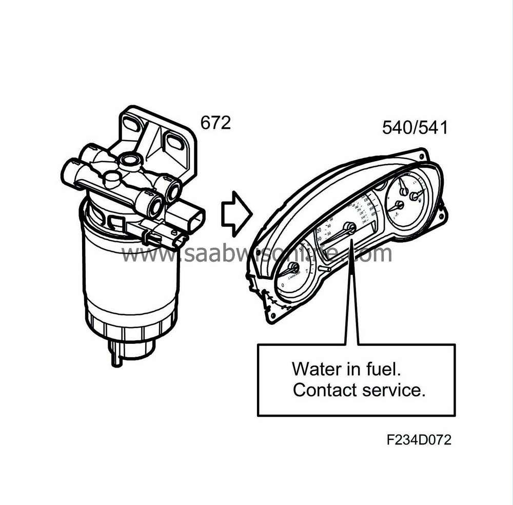
The main task of the fuel filter is to prevent particles of dirt from entering the fuel system. The pore size of the filter compound in 3-5 micrometers. In the filter is also a sensor for detecting whether there is any water in the fuel. The filter holder also contains a preheater element and sensor for the fuel temperature.
Should the separated amount of water exceed 60 ml, the driver will be made aware of it with a message on SID: Water in fuel, contact garage. At most, the filter can contain 100 ml of water. The spin-on fuel filter is located on a bracket on the left-hand side of the tank.
| High-pressure pump |
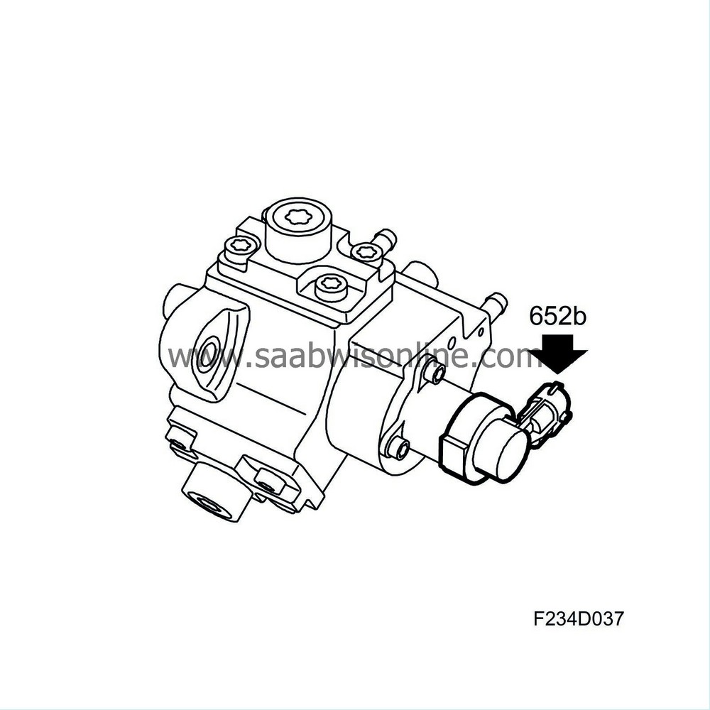
The three-cylinder high-pressure pump delivers the injection pressure, which can be up to 160 MPa (1600 bar). As the engine's fuel requirements vary over a wide range, the fuel pressure that is supplied by the high-pressure pump to the fuel rail must be regulated. This is done with the fuel control valve (652b).
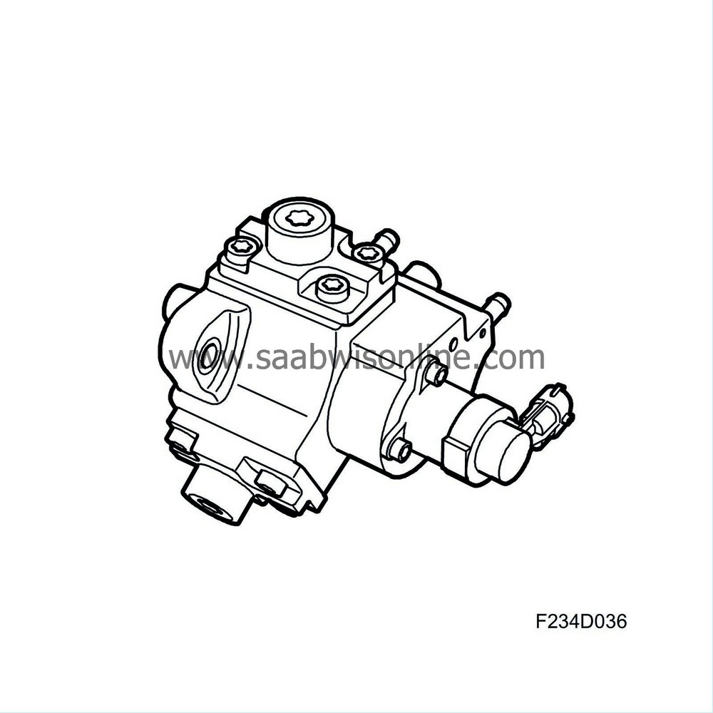
The fuel control valve (652b) on the high-pressure pump is used to restrict the fuel supply to the inlet side of the pump. If fuel requirement is low, the pump supply is restricted so that the cylinders are not completely filled. The pump capacity is regulated, which means its power requirement drops. The high-pressure pump is driven by the camshaft drive and has a given ratio to the crankshaft. Take this into account when replacing the timing belt or replacing the high-pressure pump.
| Fuel quantity control valve, high-pressure pump (652b) |
The fuel regulator valve (652b) controls the amount of fuel to the high pressure pump. In this way, the high pressure pump can be prevented from running "flat out" (with full pump chamber) when fuel requirements are low. ECM controls the valve and measures the result in the form of attained fuel pressure in the fuel rail. If necessary, the PWM signal to attain requested pressure will be corrected. The valve mounted on the high pressure pump cannot be changed separately at present. If there is a fault with the valve, the whole unit comprising the high pressure pump with valve must be changed.
| Fuel rail/reservoir |
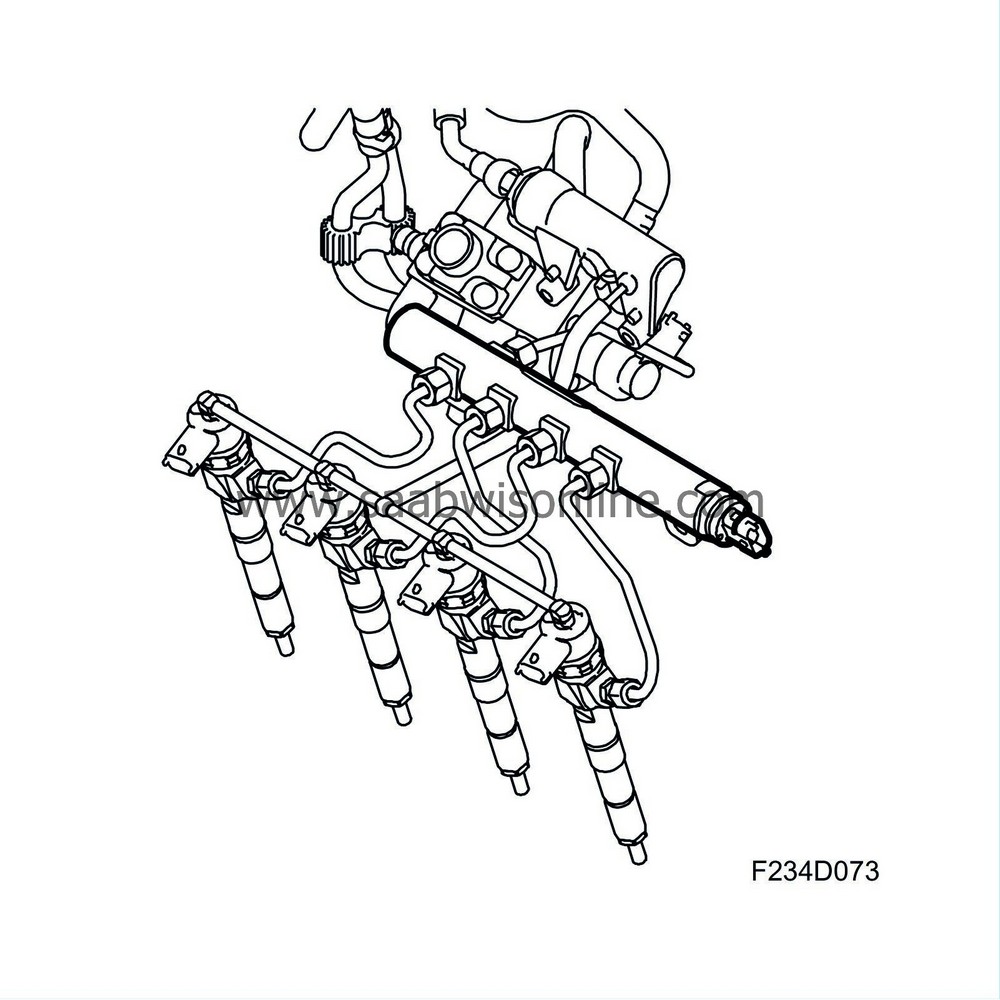
The function of the fuel rail/reservoir is to distribute the fuel to the four cylinders and to act as a reservoir to reduce pulsation in the fuel pressure. The fuel rail has connections for the high-pressure fuel from the high-pressure pump and the return fuel. A pressure sensor is mounted on the left-hand side of the fuel rail. The volume in the fuel rail is about 20 cm 3 .
16V:
8V:
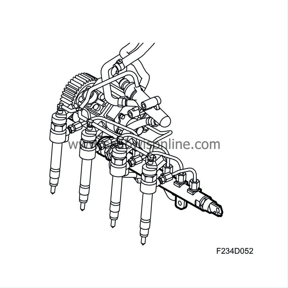
The volume, shape and location of connections have been tested thoroughly to avoid problems with pulsating fuel pressure, which would cause uneven distribution of fuel to the four nozzles.
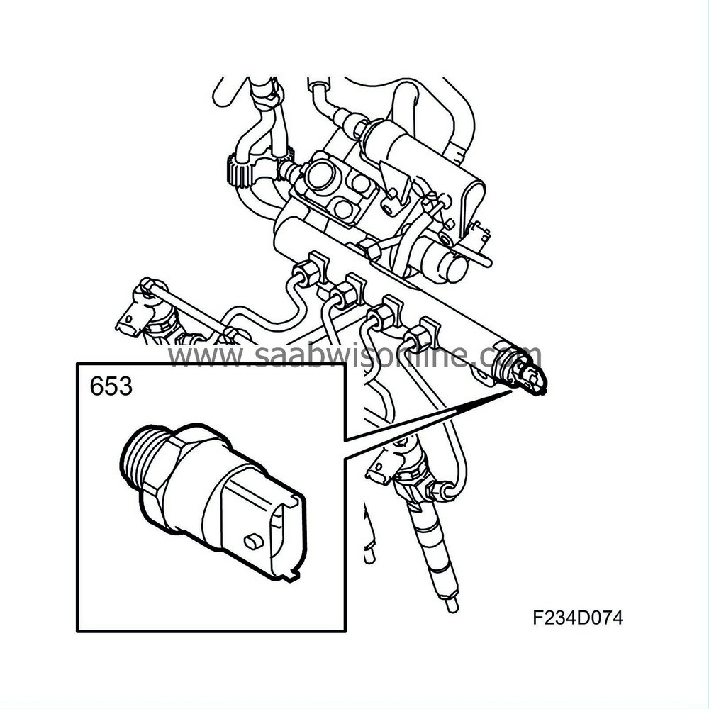
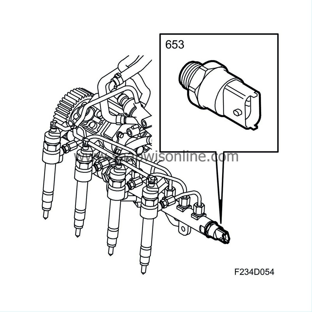
| Fuel pressure sensor, fuel rail (653) |
The fuel pressure sensor (653) is mounted on the left-hand side of the fuel rail. It measures the fuel pressure so that the engine management system is aware when the requested pressure has been attained. It is controlled by ECM with +5V and the output voltage is within range 0.5-4.5V. When changing the pressure sensor, the diagnostic tool must be connected to reset adaptation values. Select Menu - Engine - Engine management system - Adjustment - Fuel Pressure Sensor Replaced.
16V:
8V:
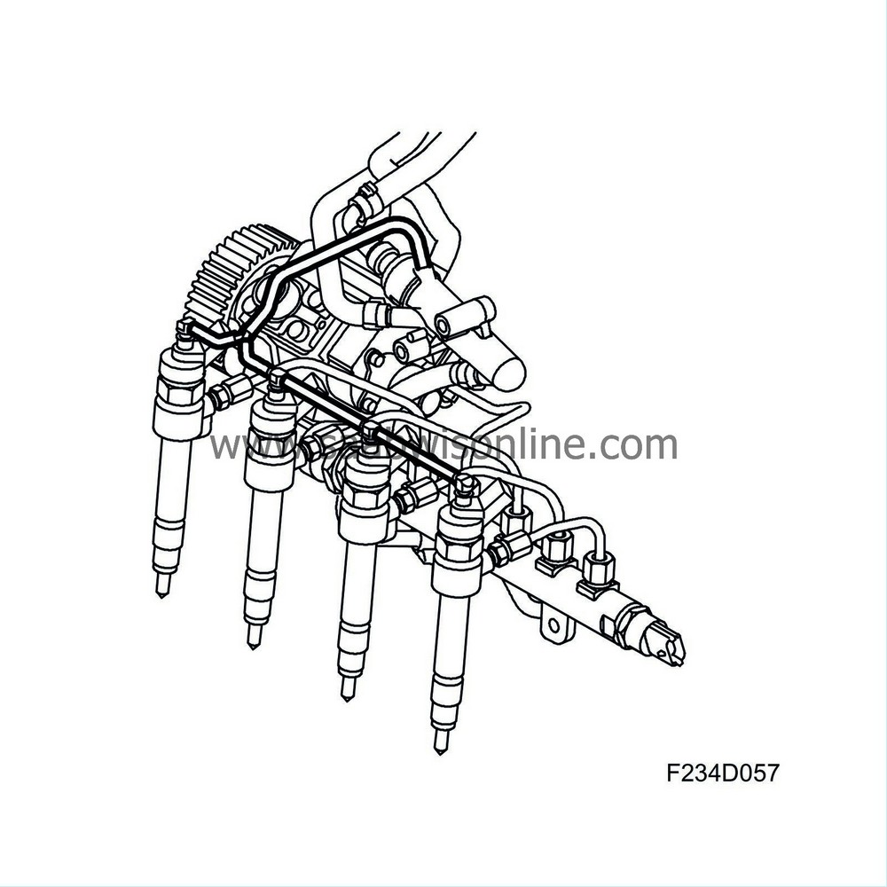
| High-pressure pipe |
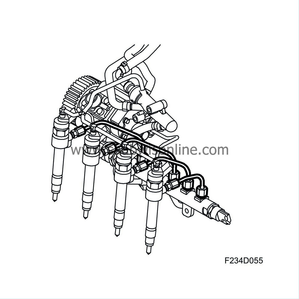
The high pressure pipe is a connection pipe between the fuel rail and the injector. It is made of steel.
16V:
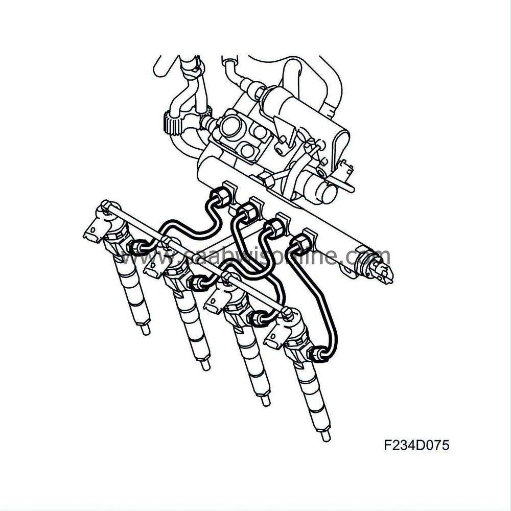
8V:
| Injectors |
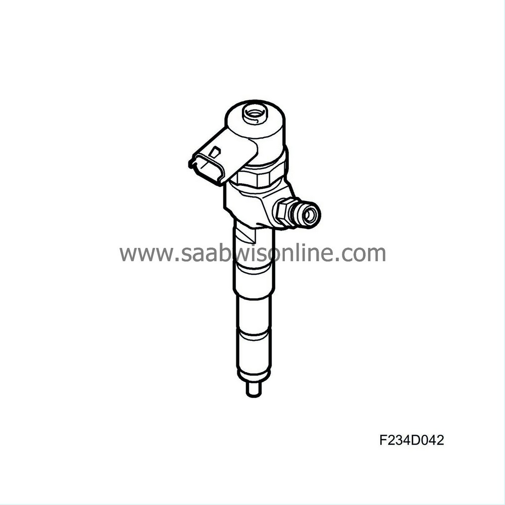
Electrically controlled injectors (206a-d) that inject fuel into the combustion chamber. The injectors have six holes, giving six jets of fuel on the Z19DT. The Z19DTH has seven holes. The holes through which the fuel is injected has a diameter of 0.145 mm (Z19DT), 0.141 (Z19DTH). As a comparison, a normal strand of hair is 0.08 mm. The holes must be very small so that the fuel will atomise into small drops. Certain manufacturing tolerances are just a few thousandths of a millimetre. Consequently, it is essential that dirt does not enter into the fuel system.
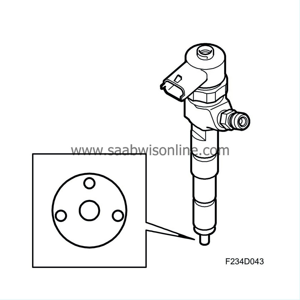
The injectors are low-ohmic and are controlled by the ECM according to the peak and hold principle. This means that an opening pulse is sent first with a rather high current (peak) in order to obtain a rapid response from the injector. After a certain period of time, the nozzle is assumed to be open and the current will be limited by ECM (hold). ECM can inject fuel up to five times per working stroke with a maximum injection timing of around 1 ms. That is faster than a wink of the eye.
The injection volume is, for example, about 1 mm 3 for the pilot injection, to be compared with a drop of water that is around 30 mm 3 . Consequently, the injector must be regarded as a precision instrument.
| Important | ||
|
If the injectors are to be refitted, mark the injectors so that they can be refitted to the same cylinder. |
||
| Important | ||
|
If new injectors are to be fitted, read and make a note of its classification code. The code is to be used when programming using the diagnostic tool. |
||
16V:
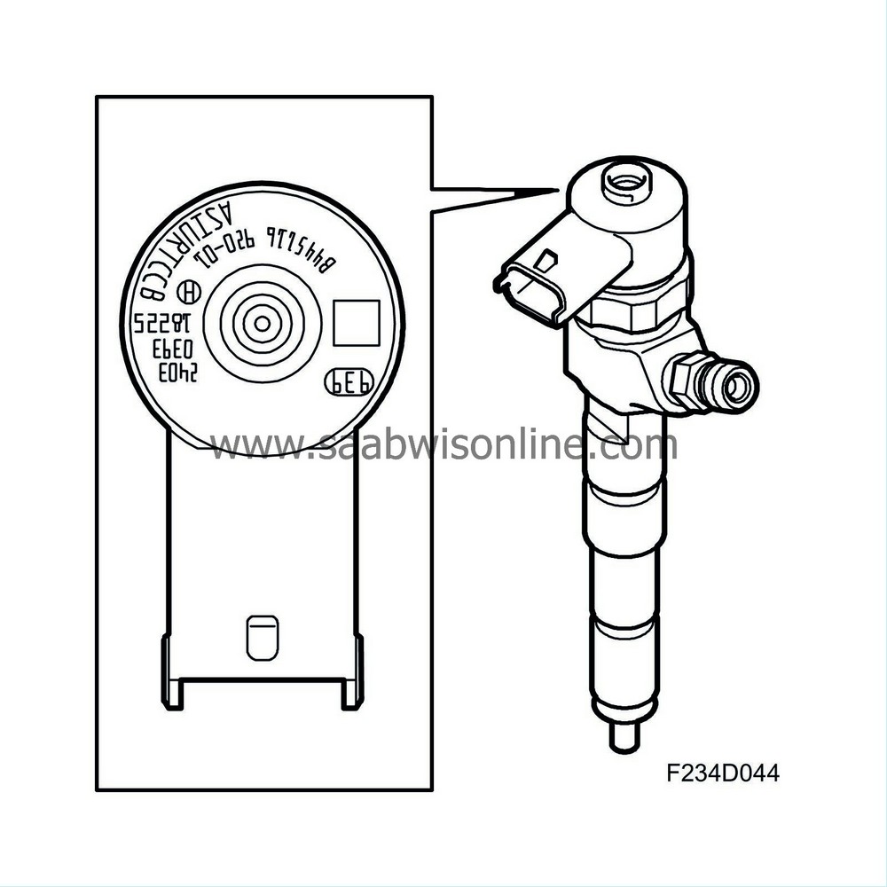
8V:
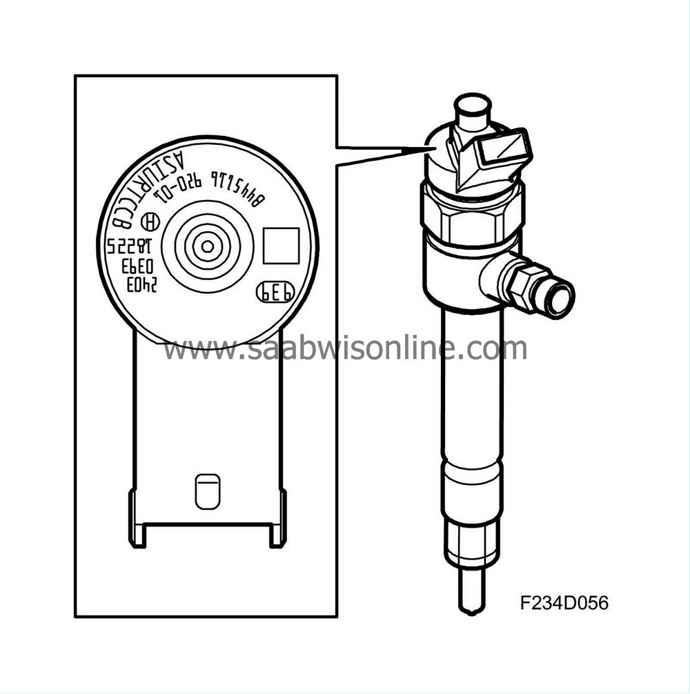
The injectors are given a final check after manufacture and receive a classification code depending on their characteristics. This code describes the nozzle characteristics for the control module. In case of a change of injector, the diagnostic tool must be connected for programming. Select Menu - Engine - Engine management system - Adjustment - Injector Replaced. The classification code must then be specified.
| Return hoses/pipes |
The hoses are used to handle the return fuel from the injectors. A controlled leakage occurs in the injectors and passes back to the fuel tank via the fuel return hoses, return fuel container and then to the return fuel line.
16V:
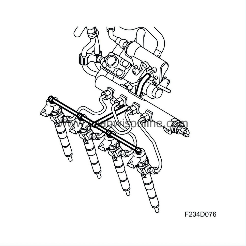
8V:
| Return fuel container |
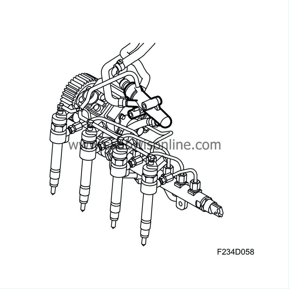
The container where the return fuel from the high-pressure pump and injectors is collected. Running from the return fuel container is a line to the fuel tank, the return line. Of the fuel delivered by the high-pressure pump, about three quarters of it passes back via the return fuel container.
16V:
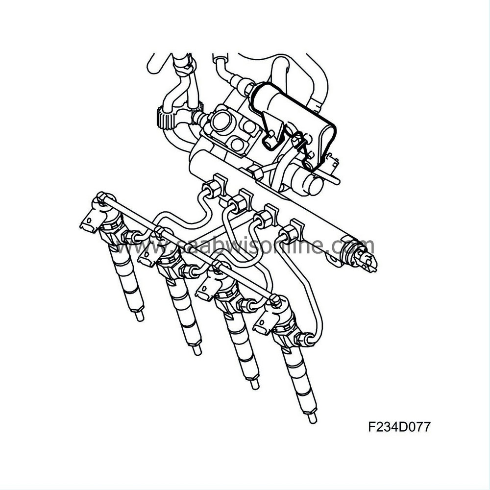
8V:
| Function description |
Mounted in the 58-litre fuel tank is the fuel pump unit. It comprises a feed pump (323) that presses fuel to the high-pressure pump and a fuel level sensor (46) that is connected to ECM (595).
The feed pump is mounted in a container from which it draws fuel. The container fills with fuel using an ejector pump driven by the return fuel flow. This is to ensure the container is always full so that the feed pump does not run empty and draw air, e.g. when lurching hard.
When the key is turned to "ON", ECM activates the fuel pump relay (102) during the glow duration plus a further 15 seconds to build up fuel pressure. The fuel pump will subsequently stop, ECM will activate the relay when the crankshaft starts to rotate. Fuel with a pressure of around 4 bar is now fed via the fuel line to the fuel filter, where the fuel is filtered and any water separated. If necessary, ECM will heat the fuel.
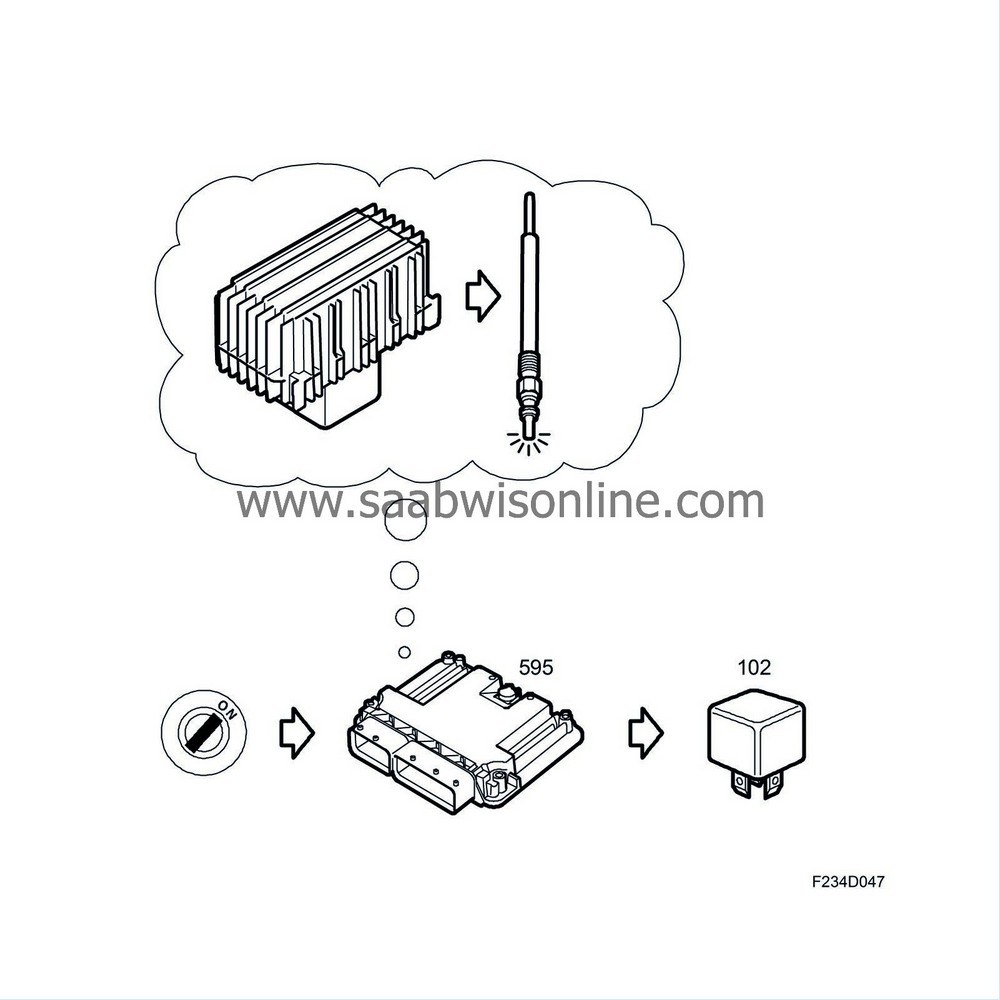
ECM measures the temperature using the fuel temperature sensor (651). Inside the fuel filter is a preheating element powered via the preheating relay (641), which ECM activates for preheating. If the filter is full of water, it must be drained and the driver will be made aware of this with the SID message: Water in Fuel, Contact Service.
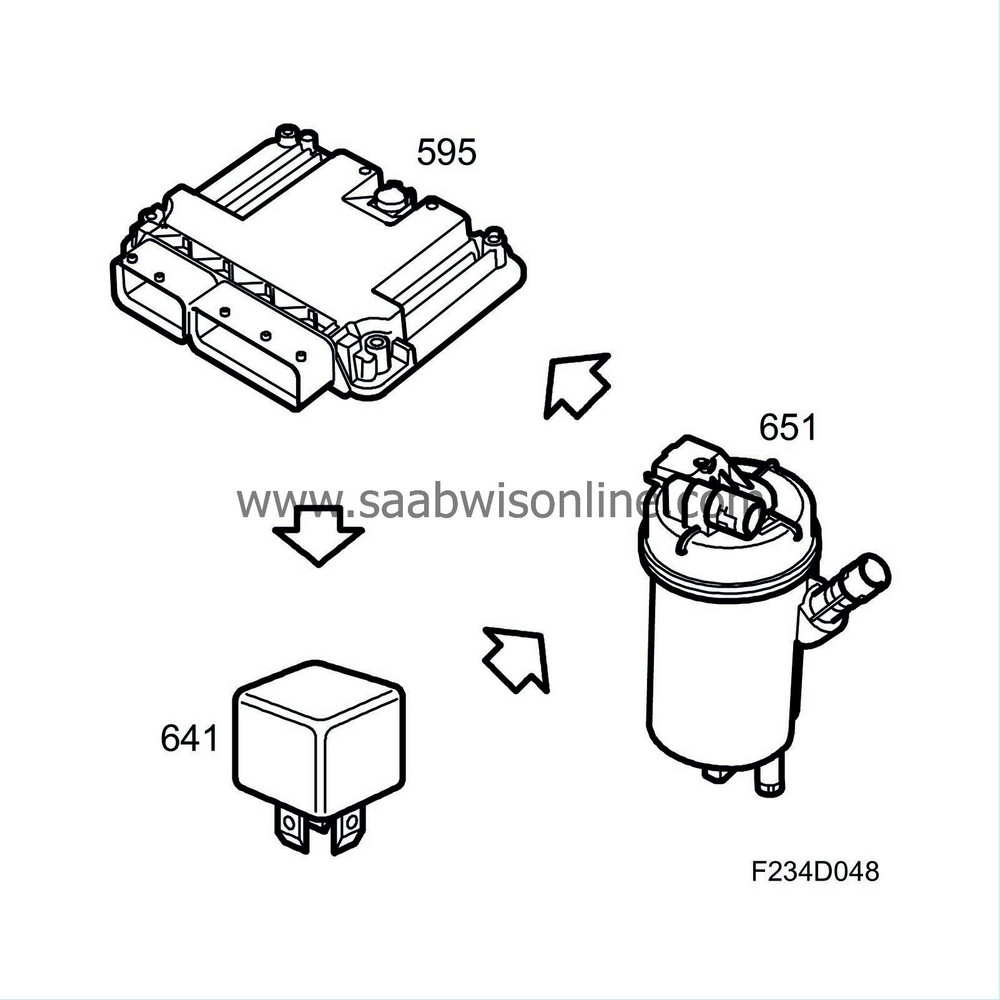
Fuel passes from the fuel filter to the high-pressure pump. The inlet to the high-pressure pump has a fuel regulator valve (652b) used to regulate the fill factor of the high-pressure pump element. The fuel regulator valve (652b) is controlled by the ECM with a PWM voltage. Since the engine fuel requirements vary over a large range, the fuel pressure supplied by the high-pressure pump to the fuel rail must be regulated.

The fuel from the high-pressure pump passes via a steel pipe to the fuel rail. This is made of steel and has a value of 20 cm 3 . The volume, shape and location of connections have been tested thoroughly to avoid problems with pulsating fuel pressure, which would cause uneven distribution of fuel to the four nozzles.
From the fuel rail, fuel passes to the injectors via steel pipes. The length of the pipes are all the same to prevent phenomena such as uneven fuel distribution.
The injectors are mounted in the cylinder head and fuel is injected centrally into the combustion chamber. The combination of six holes in the nozzle, centrally located injectors and the shape of the combustion changer offers a good mixture of fuel in the air.
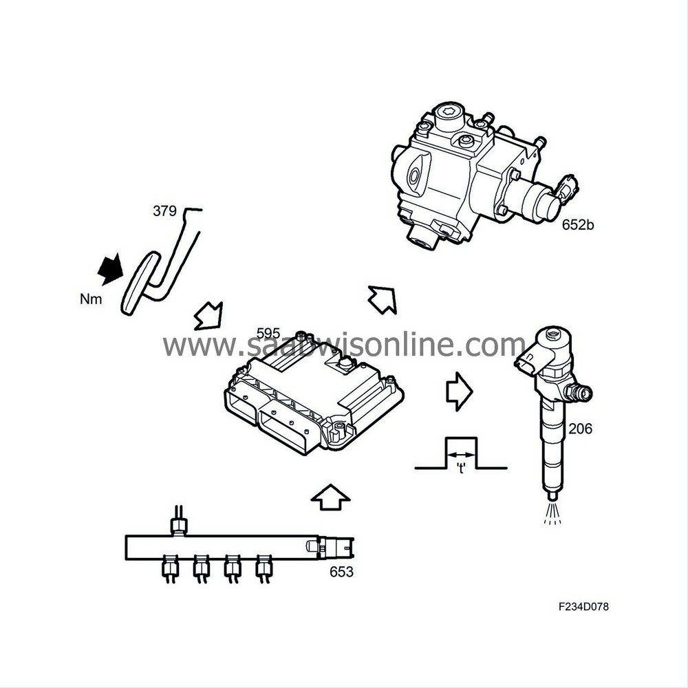
ECM controls the opening duration of the injector and the timing (crankshaft position). Maximum opening duration is in the region of 1 ms. The injectors are controlled directly by ECM, which also calculates the injected quantity using the requested torque as main parameter. The request comes from the accelerator pedal (379), for example, or the cruise control and a number of internal compensations then add or subtract torque. The result is a total torque request that is converted to injection timing. Meanwhile, ECM calculates the necessary air mass that is required for the fuel quantity in question so that the engine can deliver high output with low fuel consumption and low emissions. This request is sent to turbo control. If the air mass is below the smoke level, the injected fuel quantity will be reduced until the air mass exceeds the smoke limit.


