(367-2684) Poor sound (crackling/interference) in loudspeakers
Symptom: Poor sound (crackling/interference) in loudspeakers.
|
TECHNICAL SERVICE BULLETIN
|
|
Bulletin Nbr:
|
367-2684
|
|
Date:
...........
|
November 2007
|
|
Market:
|
all
|
|
|
Poor sound (crackling/interference) in loudspeakers
|
Saab 9-3 M07- within the following Vehicle Identification Number range:
The wiring harness contains an uninsulated wire which could be damaged if bent too much.
In the case of customer complaint, the following procedure must be carried out.
Symptom description
Poor sound (crackling/interference) in loudspeakers.
12783014 Wiring harness
12783016 Wiring harness, cars with satellite radio receiver (XM)
92 150 191 Cable ties (LHD x 7 and RHD x 5)
Fabric tape, see www.tesa.com or www.3m.com
|
Note
|
|
The procedure differs between LHD and RHD, follow the relevant procedure.
|
|
1.
|
Remove the audio/navigation unit, see WIS - 3. Electrical system - Head unit, audio/audio with navigation, Adjustment/Replacement.
|
|
2.
|
Remove the glove box, see WIS - 8. Body - Interior equipment - Adjustment/Replacement.
|
|
3.
|
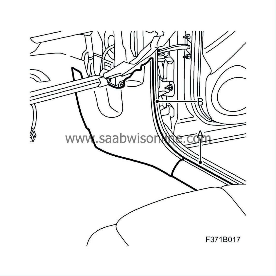
Remove the scuff plate (A) and the lower cover (B) on the right-hand side.
|
|
4.
|
Route the new wiring harness up to the audio/navigation unit along the existing panel harness.
|
|
5.
|
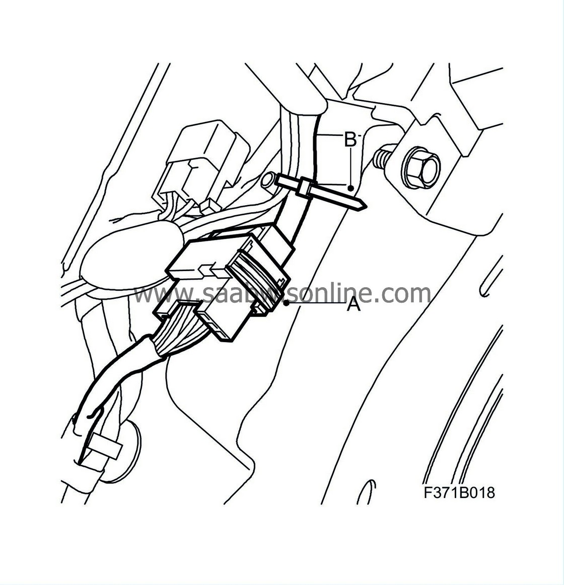
Unplug the connector H33-4 (A) and expose the wiring harness by cutting the cable tie (B) to the clip.
|
|
6.
|
Replace the wiring harness in connector H33-4. Make sure that the new pins are in the correct position:
|
|
|
•
|
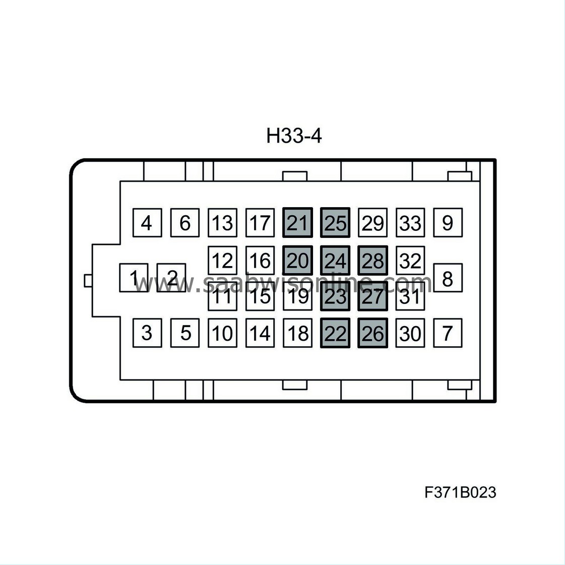
Extract the connections 20 - 28 in connector H33-4.
|
|
|
•
|
XM:
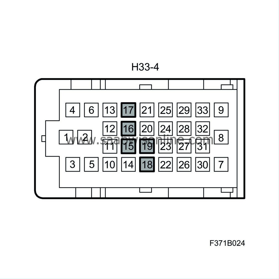
Extract the connections 15 - 19 in connector H33-4.
|
|
|
•
|
Cut off the pins, fold the cables back and tape them together with the wiring harness.
|
|
|
•
|
Connect wiring harness (12783014) to H33-4. Connect in accordance with the following:

Yellow -> 20
Black/yellow -> 21
Blue -> 22
Brown/blue -> 23
Brown/white -> 24
Black/blue -> 25
Black/green -> 26
Brown -> 27
Black -> 28
|
|
|
•
|
XM:
Connect wiring harness (12783016) to H33-4. Connect in accordance with the following:

Brown/white -> 15
Green -> 16
Green/white -> 17
Grey/black -> 18
Black -> 19
|
|
7.
|
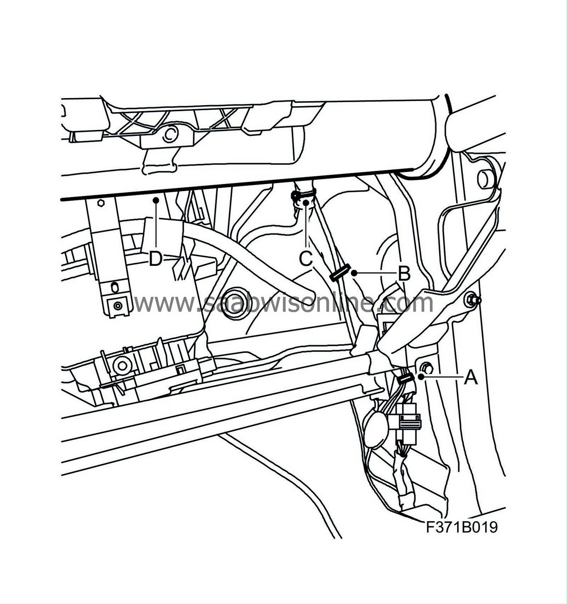
Secure the wiring harness at the right-hand A-pillar together with the normal wiring harness between the audio/navigation unit and H33-4.
|
|
|
•
|
Secure with cable ties to the clip (A).
|
|
|
•
|
Secure with cable ties to the duct (C, D).
|
|
8.
|
Replace the wiring harness for the audio/navigation unit (353/635). Make sure that the new pins are in the correct position:
|
|
|
•
|
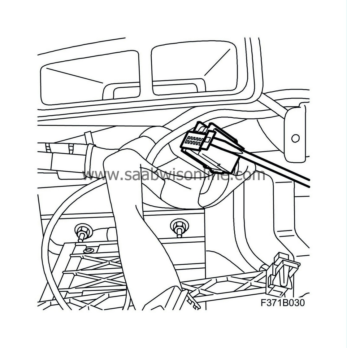
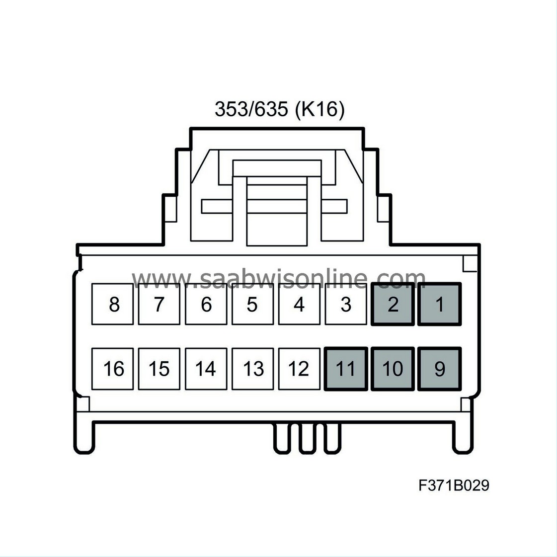
Remove the secondary catch in connectors K14 and K16.
|
|
|
•
|
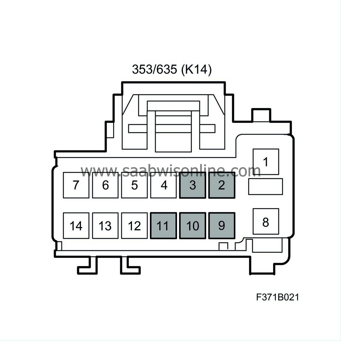
Extract the connections 2, 3, 9, 10, 11 in connector K14.
|
|
|
•
|
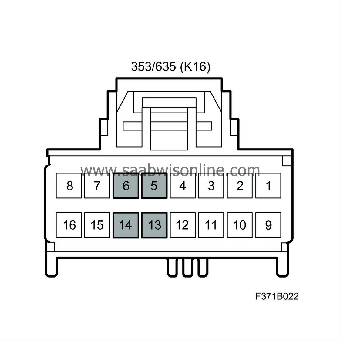
Extract the connections 5, 6, 13, 14 in connector K16.
|
|
|
•
|
XM:
Extract the connections 1, 2, 9, 10, 11 in connector K16.
|
|
|
•
|
Cut off the pins, fold the cables back and tape them together with the wiring harness.
|
|
|
•
|
Connect wiring harness (12783014) to K14. Connect in accordance with the following:

Blue -> 2
Yellow -> 3
Brown/blue -> 9
Black/yellow -> 10
Black -> 11
|
|
|
•
|
Connect wiring harness (12783014) to K16. Connect in accordance with the following:

Black/green -> 5
Brown/white -> 6
Brown -> 13
Black/blue -> 14
|
|
|
•
|
XM:
Connect wiring harness (12783016) to K16. Connect in accordance with the following:

Green -> 1
Green/white -> 2
Brown/white -> 9
Grey/black -> 10
Black -> 11
|
|
|
•
|
Fit the secondary catch in connectors K14 and K16.

|
|
9.
|
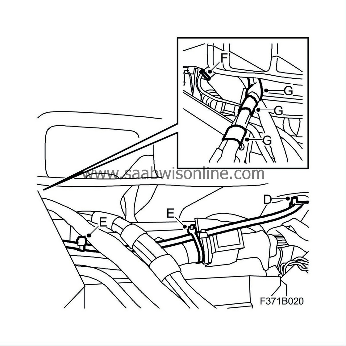
Secure the wiring harness together with the normal wiring harness between the audio/navigation unit and H33-4.
|
|
|
•
|
Secure with cable ties to the duct (D).
|
|
|
•
|
Secure with cable ties to the normal cable harness (E, F).
|
|
|
•
|
Secure the wiring harness to the audio/navigation unit's wiring harness with tape (G).
|
|
10.
|
Fit the audio/navigation unit, see WIS - 3. Electrical system - Head unit, audio/audio with navigation, Adjustment/Replacement.
|
|
11.
|
Plug in connector H33-4.
|
|
12.
|
Fit the scuff plate (A) and the lower cover (B) on the right-hand side.

|
|
13.
|
Fit the glove box, see WIS - 8. Body - Interior equipment - Adjustment/Replacement.
|
|
1.
|
Remove the scuff plate (A) and the lower cover (B) on the right-hand side.

|
|
2.
|
Remove the sound insulation panel on the driver's side, see WIS - 8. Body - Interior equipment - Adjustment/Replacement.
|
|
3.
|
Remove the main instrument unit, see WIS - 3. Electrical system - Driver Information, main instrument unit and SID - Adjustment/Replacement.
|
|
4.
|
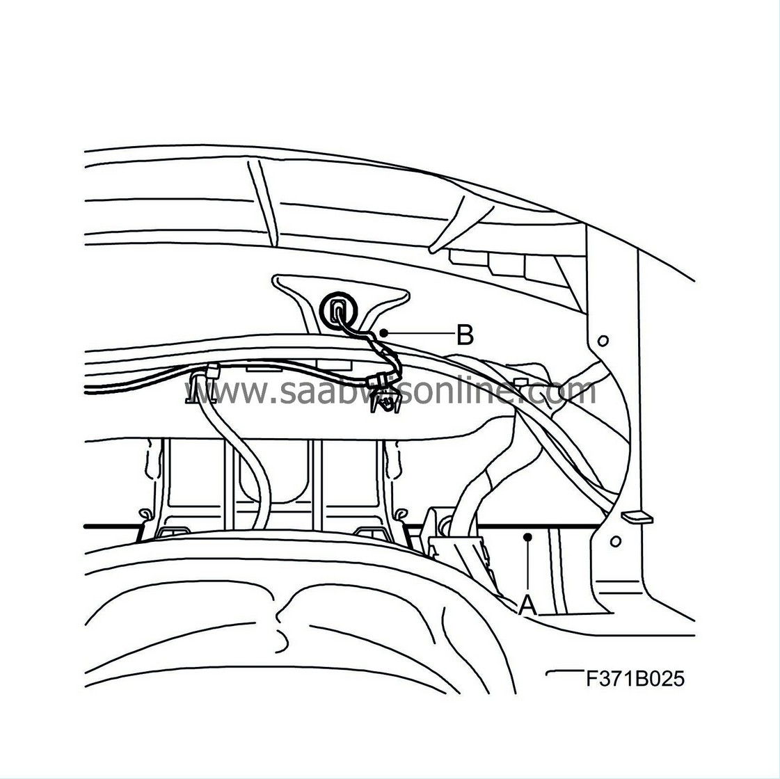
Route the new wiring harness up between the audio/navigation unit and H33-4 along the existing panel harness, out on the right-hand side of the panel where the wiring harness is routed in front of the steering wheel member (A). The wiring harness must be routed under the wiring harness for the temperature sensor (B) in the air duct.
|
|
5.
|
Unplug the connector H33-4 (A) and expose the wiring harness by cutting the cable tie (B) to the clip.

|
|
6.
|
Replace the wiring harness in connector H33-4. Make sure that the new pins are in the correct position:
|
|
|
•
|
Extract the connections 20 - 28 in connector H33-4.

|
|
|
•
|
Cut off the pins, fold the cables back and tape them together with the wiring harness.
|
|
|
•
|
Connect wiring harness (12783014) to H33-4. Connect in accordance with the following:

Yellow -> 20
Black/yellow -> 21
Blue -> 22
Brown/blue -> 23
Brown/white -> 24
Black/blue -> 25
Black/green -> 26
Brown -> 27
Black -> 28
|
|
7.
|
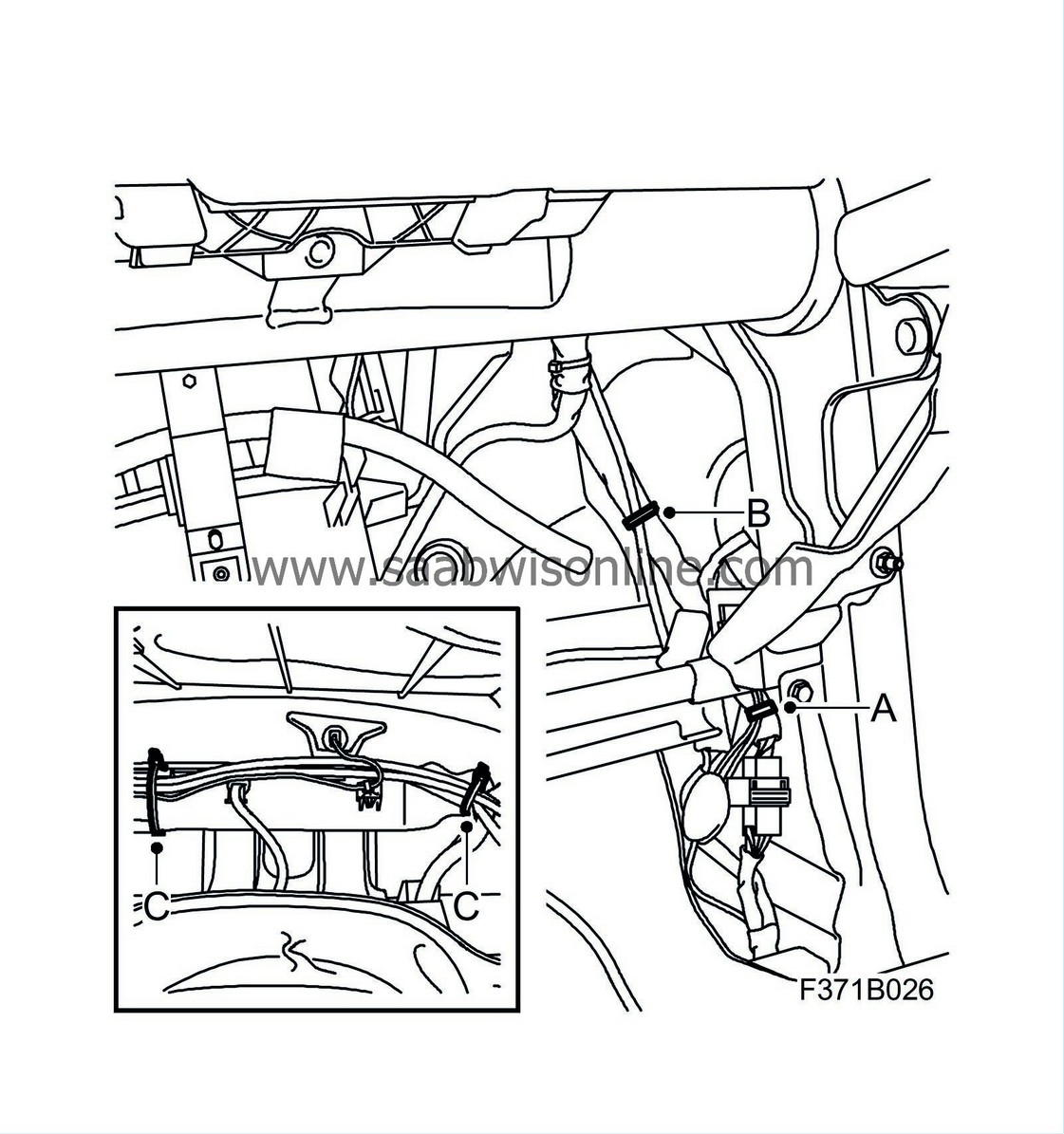
Secure the wiring harness at the right-hand A-pillar together with the normal wiring harness between the audio/navigation unit and H33-4.
|
|
|
•
|
Secure with cable ties to the clip (A).
|
|
|
•
|
Secure with cable ties to the duct outlet (B).
|
|
|
•
|
Secure with cable ties to the steering wheel member (C).
|
|
8.
|
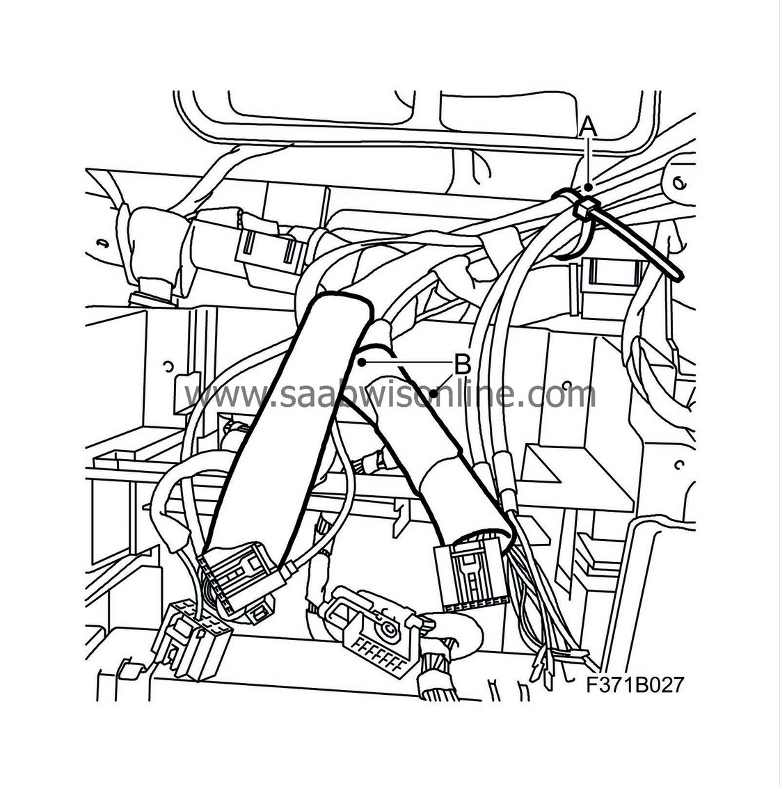
Secure the wiring harness in the instrument panel together with the normal wiring harness between the audio/navigation unit and H33-4.
|
|
|
•
|
Secure with cable ties to the normal cable harness (A).
|
|
|
•
|
Remove the tape (B) on the protective hoses and route the wiring harness through the hoses (B). Check that the correct cables are routed through the relevant hose.
|
|
9.
|
Replace the wiring harness to the audio/navigation unit. Make sure that the new pins are in the correct position:
|
|
|
•
|
Remove the secondary catch in connectors K14 and K16.

|
|
|
•
|
Extract the connections 2, 3, 9, 10, 11 in connector K14.

|
|
|
•
|
Extract the connections 5, 6, 13, 14 in connector K16.

|
|
|
•
|
Cut off the pins, fold the cables back and tape them together with the wiring harness.
|
|
|
•
|
Connect wiring harness (12783014) to K14. Connect in accordance with the following:

Blue -> 2
Yellow -> 3
Brown/blue -> 9
Black/yellow -> 10
Black -> 11
|
|
|
•
|
Connect wiring harness (12783014) to K16. Connect in accordance with the following:

Black/green -> 5
Brown/white -> 6
Brown -> 13
Black/blue -> 14
|
|
|
•
|
Fit the secondary catch in connectors K14 and K16.

|
|
10.
|
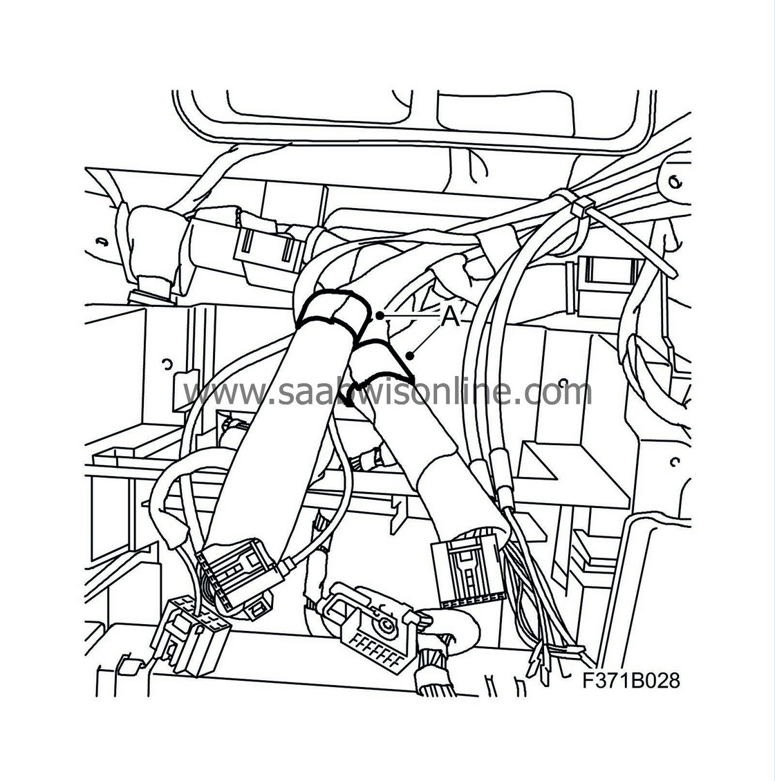
Tape around the ends of the protective hoses (A).
|
|
11.
|
Plug in connector H33-4.
|
|
12.
|
Fit the sound insulation panel on the driver's side, see WIS - 8. Body - Interior equipment - Adjustment/Replacement.
|
|
13.
|
Fit the scuff plate (A) and the lower cover (B) on the right-hand side.

|
|
14.
|
Fit the main instrument unit, see WIS - 3. Electrical system - Driver Information, main instrument unit and SID - Adjustment/Replacement.
|
|
Warranty/Time Information
|
In the case of customer complaint and if the car is
within the warranty period
, use the following information to fill out the claim:
Failed Object: 36712
Fault/Reason code: 17
Location code: 09 (US=9)
Warranty Type (US): 01
Repair/Action code: 01
Labour Operation (US): 3671202
Labour Operation (CA): N6632
Time:
RHD:
1.4 hr
LHD:
1.3 hr


