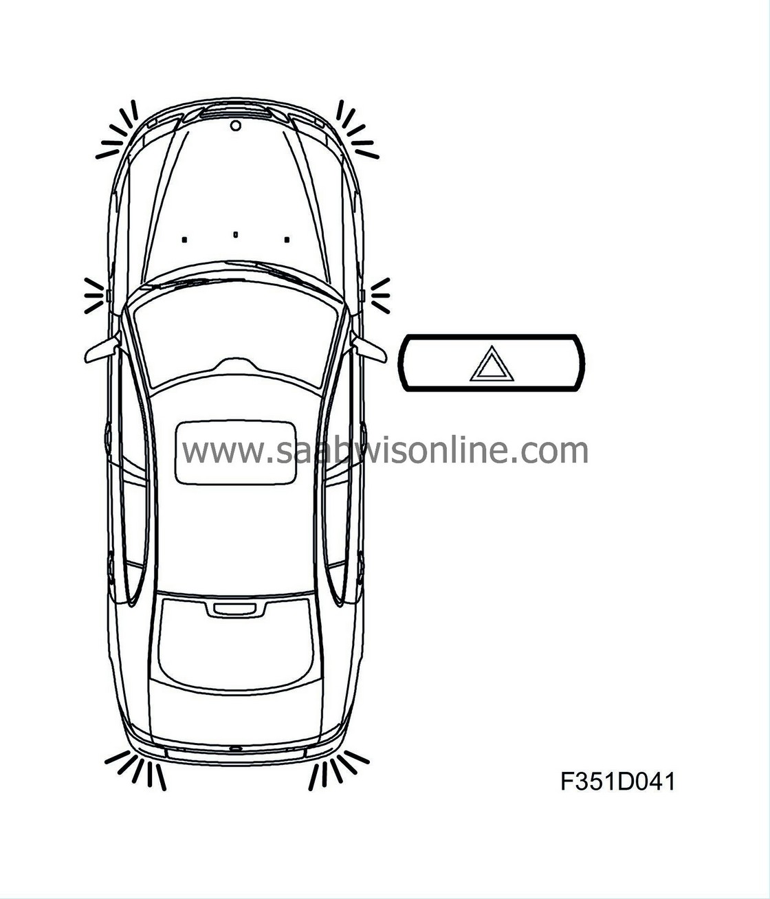
Hazard flashers, detailed description
| Hazard flashers, detailed description |
Warning function where all direction indicators are activated with the switch for hazard warning lights. The switch is located on the ACC unit panel. The hazard warning lights can be activated independently of the position of the ignition switch.


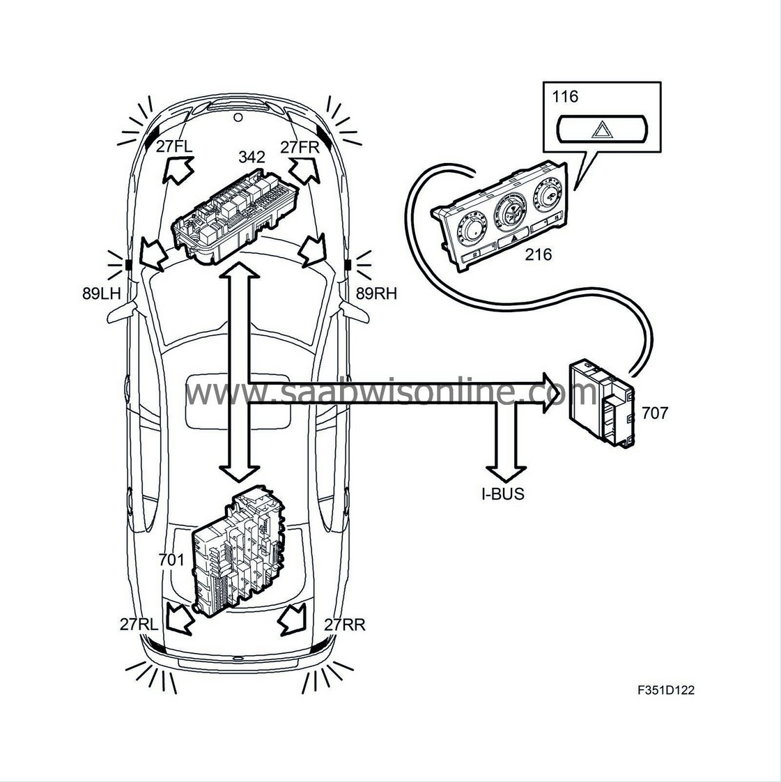
The direction indicators are located in the front headlamps, front wings and in the rear light clusters. Upon activation of the switch (25), BCM (707) sends a bus message to the fuse boxes in the engine bay and the luggage compartment, which govern the front and rear direction indicators, respectively. See Direction indicators and hazard flashers, bus information .
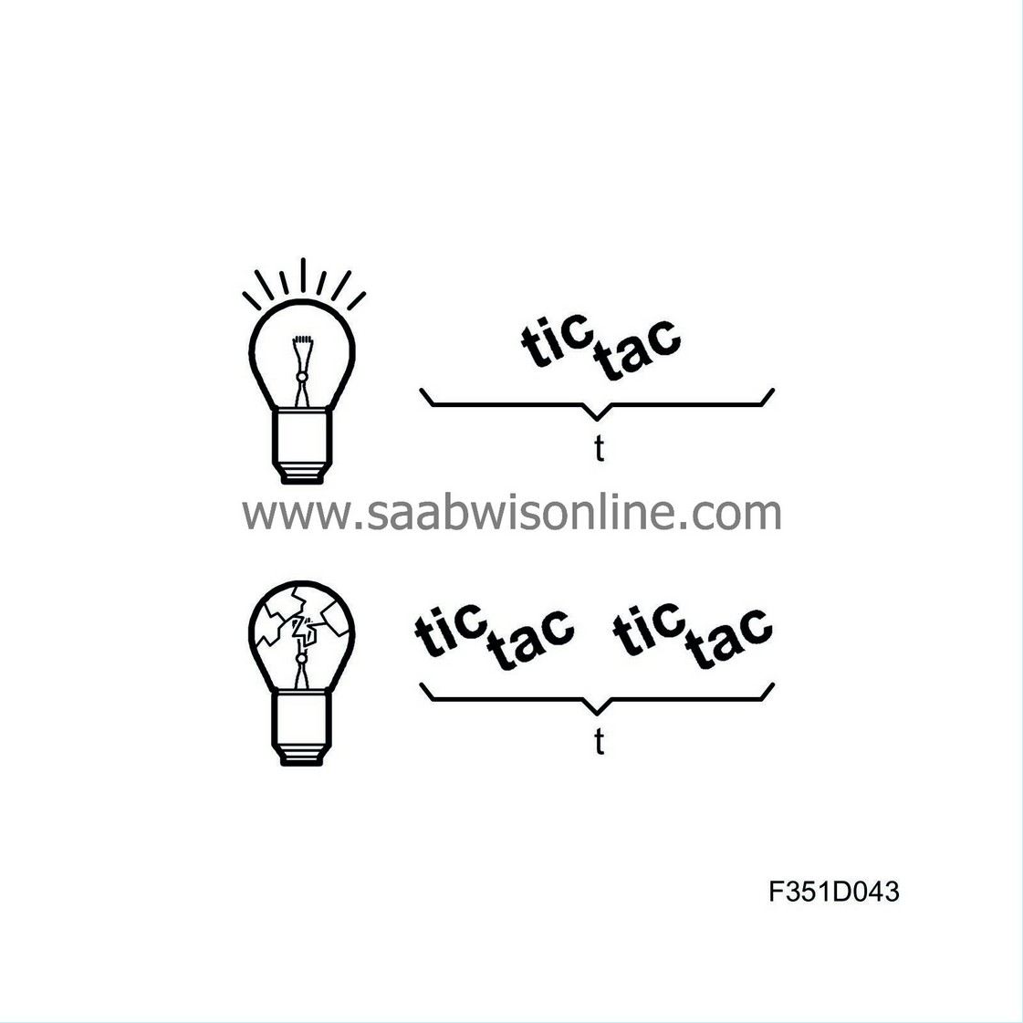
Flash frequency is 90 flashes per minute. In the event of filament breakage, flash frequency is increased to 180 flashes per minute and a warning message is displayed in SID.

| Front direction indicators |
The front direction indicators (27FL/FR) and side direction indicators (89LH/RH) are supplied power from UEC (342). The direction indicator function in UEC is controlled by bus messages from BCM. UEC activates the correct direction indicator output based on which bus messages are sent by BCM.
UEC supplies voltage to the front left direction indicator (27FL) from pin 3 (F) and the side direction indicator (89FL) from output pin 4 (F).
UEC supplies voltage to the front right direction indicator (27FR) from pin 2 (F) and the side direction indicator (89RH) from output pin 9 (F).
Filament monitor
UEC supplies current in each circuit. In the event of filament breakage in the front left direction indicator, for example, UEC sends the bus message "Front left indicator not working ON" for pin 3 (F). This bus message is used by BCM (707) and ICM (736). BCM doubles flash frequency to 180 flashes per minute. ICM displays a warning message in SID.| Rear direction indicators |
Power is supplied to the rear direction indicators (27RL/RR) from REC (701). The direction indicator function in REC is governed by bus messages from BCM. REC activates the correct direction indicator function based on which bus messages BCM sends.
REC supplies power to the rear left direction indicator (27RL) from pin 8 (R-D) and to the rear right direction indicator (27RR) from pin 6 (R-D)
Filament monitor
REC measures the current of the respective circuit. In the event of filament breakage or the like, REC sends the bus message "Rear left indicator not working, ON" for pin 8 (R-D) or "Rear right indicator not working ON" for pin 6 (R-D). This bus message is used by BCM (707) and ICM (736). BCM doubles flash frequency to 180 flashes per minutes. ICM displays a warning message in SID.| Indicator symbol in MIU |
MIU uses the bus messages "Activate front left indicator ON" and "Activate front right indicator ON" to activate the indicator symbol for the left or right direction indicator.
| Acoustic indicator |
The MIU uses the bus messages "Activate front left direction indicator" ON and "Activate front right direction indicator" ON in order to, in its turn, send a bus message to the EHU (353) which activates an acoustic signal in the speakers in the MIU. The MIU handles the prioritising of all of the car's indicator and warning tone signals. If a warning message comes at the same time as the direction indicator is active then the direction indicator tone is discontinued for the time that the warning tone is active in the speakers. The warning tone has higher priority than the direction indicator tone.


