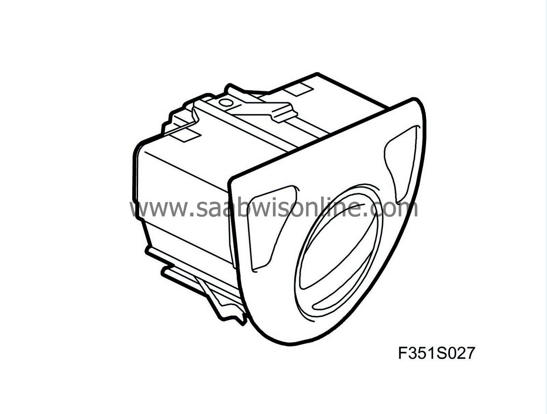
Light switch unit (684)
| Light switch unit (684) |

The light switch unit contains:
| • |
Switch, lights (10)
|
|
| • |
Headlamp levelling switch (282)
|
|
| • |
Switch, fog lights (88)
|
|
| • |
Switch, rear fog light (161)
|
|
| Main task |
Used to:
| • |
Select light position OFF, parking or headlamps
|
|
| • |
Activate front and rear fog lights
|
|
| • |
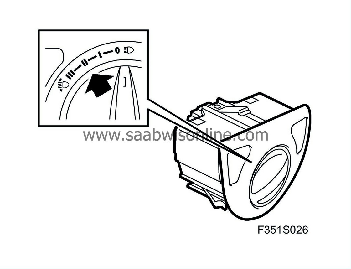
Set beam length on cars without Xenon lamps
|
|
BCM transmits switch status on the bus.
| Type |
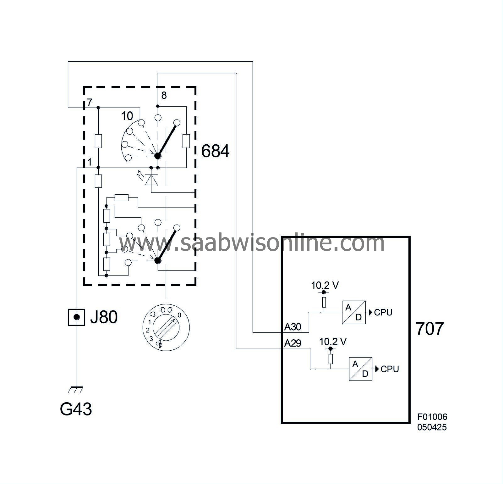
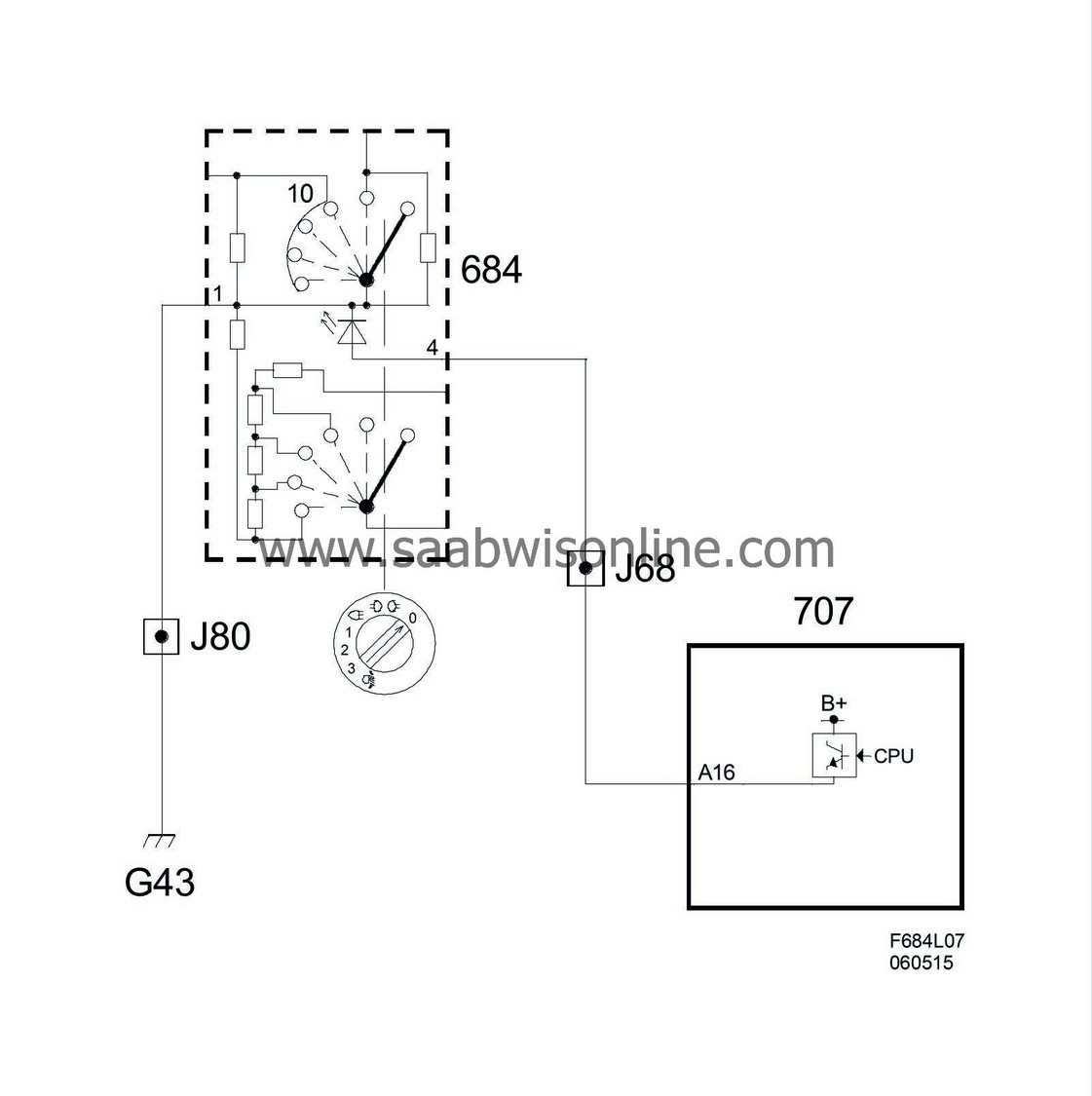
The switch is a unit consisting of a three-position knob for the headlamps, two spring-back buttons for front and rear fog lights, and LEDs to light the symbols and knob. The switch also contains four diagnostic resistors. When the knob is all the way to the right (lights off), the switch's contacts open and only two of the internal diagnostic resistors (1.8 kΩ each) are linked between each connection and ground. If the knob is turned one click to the left (parking lights), pin 2 is grounded. Another click to the left (headlamps) grounds pin 1. If the front fog light button is pressed, pin 4 is grounded, while pin 5 is grounded if the rear fog light button is pressed. If no button is pressed and the knob is in its OFF position, only the four internal diagnostic resistors (1.8 kΩ each) will be linked between each connection and ground.
On cars without xenon lamps, there are three additional knob positions to the left of the headlamp position. These are used for headlamp levelling. They are resistive multiplexing, which leads to an additional number of resistors in this variant. Five resistors are internally coupled between +15 and ground. The switch knob straight up in the headlamp position gives normal beam length. High voltage is taken out in this position between the fourth and fifth resistor calculated from ground. Each step the beam length is to be moved closer to the car, voltage is taken out closer to ground, thereby sinking.
| Connection |
The light switch is directly grounded to the body. The two pins of the lighting knob, the pin for front fog lights and the pin for rear fog light, are fed 10.2. V separately via a 1.2 kΩ resistor integrated in BCM (headlamp position has 1.5 kΩ). Voltage between each pin and ground is 0 V when the circuit is closed to ground and approx. 6 V when it is open (headlamp position 5.5 V). If the control module detects 10.2 V, it will be regarded as a break. The LEDs are grounded internally and are supplied with PWM from BCM. Headlamp levelling requires one pin for +15 and one for the output to the two headlamp levelling motors.
|
Pin No.
|
Signal type
|
Description
|
| 1 | Ground | Ground to the body. |
| 2 | Rear fog light | To BCM, Ground via depressed button |
| 3 | Front fog lights | To BCM, Ground via depressed button |
| 4 | Lighting | From BCM. + supply with PWM to LEDs |
| 5 | Headlamp beam adjustment | To the headlamp levelling motors. Drop in voltage when the knob is turned to a shorter beam length. |
| 6 | Power supply, +15 | From dashboard main fuse box pin 8 |
| 7 | Headlamps | To BCM. Grounded two steps from knob's right end position (when knob points straight up) |
| 8 | Parking lights | To BCM. Grounded one step from knob's right end position |


