Switch panel (737a)
| Switch panel (737a) |
| Location |
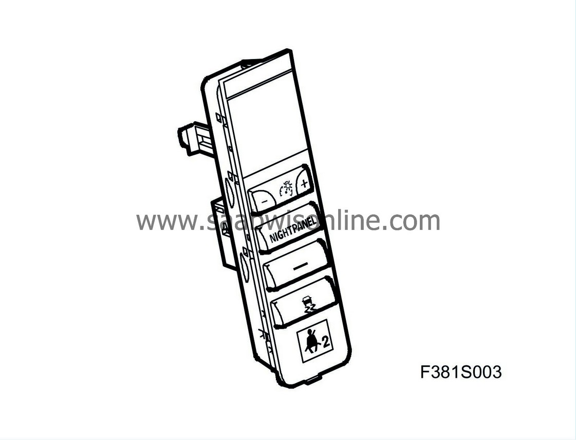
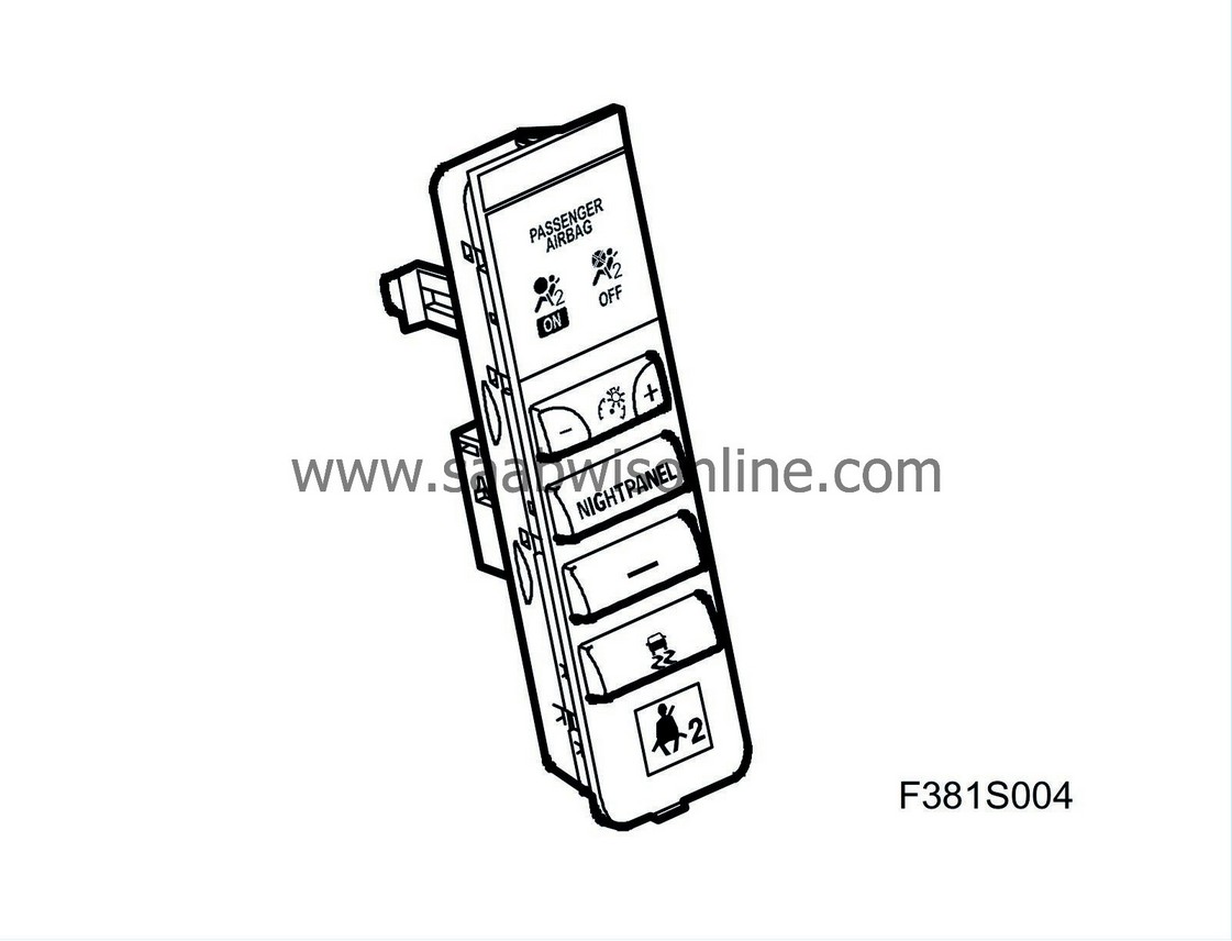
Switch panel (737a)
| Main task |
Functions in the switch panel:
| • |
adjust the brightness of the instrument illumination
|
|
| • |
turn on or off TCS or ESP function
|
|
| • |
turn on or off extra equipment (4D)
|
|
| • |
operate the soft top (CV)
|
|
| • |
Night Panel (extinguishes certain parts of instrument illumination)
|
|
| • |
Indicates passenger airbag ON/OFF, used by PPS (Passenger Presence System), certain markets
|
|
| Type |
Switch panel appearance is tied to the equipment level of the car.


For some markets, the switch panel contains LEDs that are used by the PPS control module to indicate whether the passenger airbag is ON or OFF.
The switch panel has one 12-pin connector.
| Connection |
|
Pin No.
|
Signal type
|
Description
|
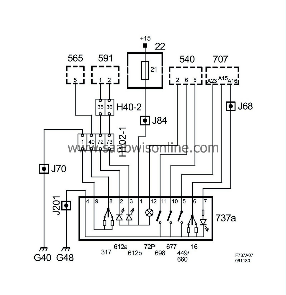
| 1 | Power supply (+15) | Power supply from IPEC |
| 2 | Input signal, indicator lamp, Passenger Airbag ON (612a) | The PPS control module grounds pin 1 to turn on the LED. |
| 3 | Input signal, indicator lamp, Passenger Airbag OFF (612b) | The PPS control module grounds pin 1 to turn on the LED. |
| 4 | Ground | |
| 5 | Input signal, indicator lamp, TCS/ESP Off | TCS/ESP deactivated. Signal via BCM. |
| 6 | Output signal, brightness adjustment of instrument lighting | Instrument lighting rheostat. Signal to BCM. |
| 7 | Background illumination | Signal from BCM. |
| 8 | Output signal, soft top up/down | Soft top up/down. Signal to STC. |
| 9 | Ground, soft top | |
| 10 | Output signal | For options/accessories, e.g. spotlights |
| 11 | Output signal, Night Panel | Night panel, off/on. Signal to MIU. |
| 12 | Input signal, indicator lamp, seat belt warning | Illuminates the seat belt warning lamp. Signal from MIU. |
Wiring diagram


