|
No.
|
Name
Location
|
Illustration
|
|
|
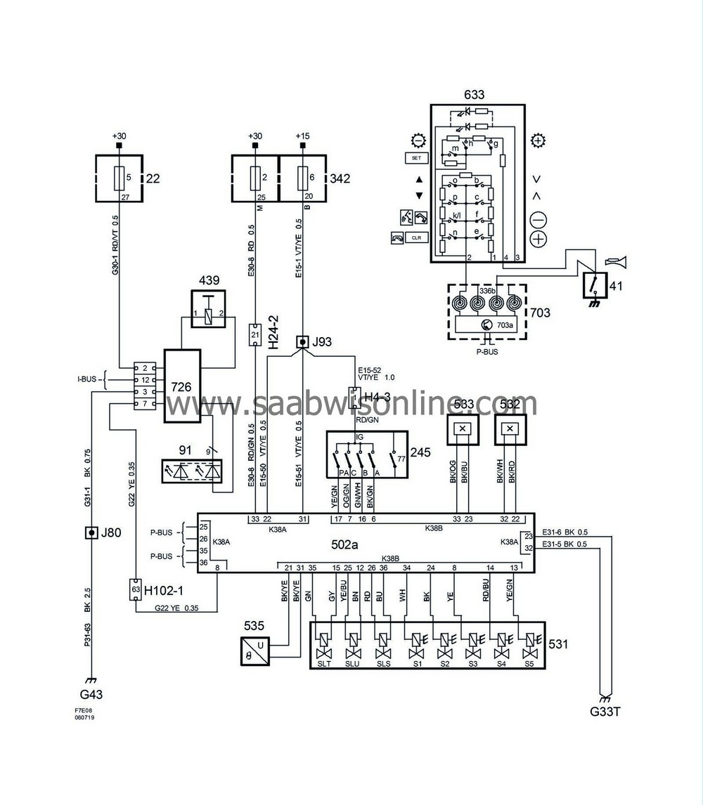
Components
|
|
|
22
|
Main fuse box, instrument panel,
on end of instrument panel by left-hand door
|
5
|
|
41
|
Horn switch,
in steering wheel rim
|

|
|
77
|
Start inhibitor switch, automatic (in 245),
in transmission range switch on transmission casing
|

|
|
91
|
Selector lever position indicator LEDs,
on front right wing
|

|
|
245
|
Transmission range switch, automatic,
on automatic transmission casing in engine bay
|

|
|
336b
|
Switch unit, steering wheel, horn/switch,
integrated in column integration module
|

|
|
342
|
Main fuse box, engine bay,
next to battery
|
2
6
|
|
439
|
Solenoid, gear selector, SHIFT LOCK,
in gear selector unit
|

|
|
502a
|
TCM, FA 57
on bracket between battery and engine
|

|
|
531
|
Solenoid valves, TCM,
on the transmission casing
|

|
|
532
|
Speed sensor, input shaft, transmission casing
on the transmission casing
|

|
|
533
|
Speed sensor, output shaft, transmission casing
on the transmission casing
|

|
|
535
|
Transmission fluid temperature sensor,
on the transmission casing
|

|
|
633
|
Switch unit, steering wheel
on steering wheel rim
|

|
|
703
|
Column integration module,
on steering column below steering wheel
|

|
|
703a
|
Control module, column integration module,
in column integration module
|
|
|
726
|
Shift lever module,
in gear selector unit
|

|
|
|
4-pin connector
|
|
|
H4-3
|
Under TCM control module
|

|
|
|
24-pin connector
|
|
|
H24-2
|
Grey connector in front of battery on side of left structural member
|

|
|
|
102-pin connector
|
|
|
H102-1
|
Under left A-pillar
|

|
|
|
Crimp connections
|
|
|
J80
|
LHD:
Approx. 80 mm from branching point grounding point G43 towards G41
RHD:
Approx. 120 mm from branching of grounding point G43 towards MIU
|

|
|
J93
|
Approx. 100 mm from branching point TCM control module (FA 57) towards the control module.
|

|
|
|
Grounding points
|
|
|
G33T
|
Upper grounding point on floor below left A-pillar
|

|
|
G43
|
On the right-hand side of the knee beam
|

|


