|
No.
|
Name
location
|
Figure
|
|
|
Components
|
|
|
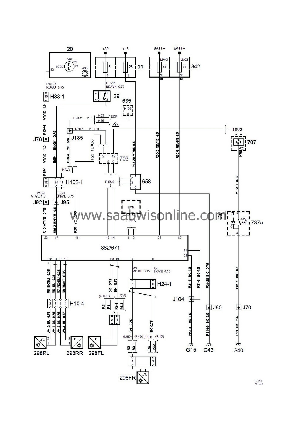
20
|
Ignition switch,
in floor console between front seats
|

|
|
22
|
Electrical centre 22
on end of instrument panel by left-hand door
|
6
26
|
|
29
|
Brake light switch,
on pedal bracket
|

|
|
298FL
|
Wheel speed sensor, front left
on left-hand steering swivel member
|

|
|
298FR
|
Wheel speed sensor, front right
on right-hand steering swivel member
|

|
|
298RL
|
Wheel speed sensor, rear left
on rear left wheel hub
|

|
|
298RR
|
Wheel speed sensor, rear right
on rear right wheel hub
|

|
|
342
|
Electrical centre 342
next to battery
|
28
33
|
|
382
|
TCS control module,
integrated in hydraulic unit behind electrical centre 342 in engine bay
|

|
|
449
|
TCS switch,
integrated in the switch panel (737a) on the instrument panel next to the main instrument unit
|

|
|
463
|
Immobilizer antenna unit,
in ignition switch
|
|
|
635
|
Unit, audio/navigation
in centre console
|

|
|
658
|
Yaw sensor
on centre tunnel under gear changing unit
|

|
|
660
|
ESP switch,
integrated in the switch panel (737a) on the instrument panel next to the main instrument unit
|

|
|
671
|
ESP control module,
integrated in hydraulic unit behind electrical centre 342 in engine bay
|

|
|
703
|
Steering column unit,
on steering shaft below steering wheel
|

|
|
737a
|
Switch panel,
on instrument panel next to main instrument unit
|

|
|
|
10-pin connectors
|
|
|
H10-4
|
Grey connector in plastic box on member next to right-hand side of fuel tank
|

|
|
|
24-pin connector
|
|
|
H24-1
|
Black connector in front of the battery under the left-hand structural member
|

|
|
|
33-pin connectors
|
|
|
H33-1
|
Black connector on console to left of ignition switch
|

|
|
|
102-pin connectors
|
|
|
H102-1
|
Under left-hand A-pillar
|

|
|
|
Crimp connections
|
|
|
J70
|
LHD:
Approx. 290 mm from branching of switch unit towards column integration module
RHD:
Approx. 360 mm from grounding point G40 towards grounding point G41
|

|
|
J78
|
LHD:
Approx. 130 mm from branching point cigarette lighter towards airbag control module
RHD:
Approx. 110 mm from branching point grounding point G41 towards connector H33-1
|

|
|
J80
|
LHD:
Approx. 80 mm from branching point grounding point G43 towards grounding point G41
RHD:
Approx. 120 mm from branching of grounding point G43 towards MIU
|

|
|
J92
|
Approx. 340 mm from branching point of bonnet switch towards cabin
|

|
|
J95
|
4D:
Approx. 60 mm from branching point left front door to engine bay
CV:
Approx. 30 mm from branching point left front door to engine bay
|

|
|
J104
|
Approx. 190 mm from branching point front left wheel speed sensor towards TCS/ESP
|

|
|
J185
|
LHD:
Approx. 240 mm from branching of switch unit towards column integration module
RHD:
Approx. 450 mm from grounding point G40 towards grounding point G41
|

|
|
|
Grounding points
|
|
|
G15
|
On left-hand structural member under battery
|

|
|
G40
|
In instrument well to the left on the knee member
|

|
|
G43
|
On right-hand side of knee member
|

|


