|
No
|
Name
location
|
Illustration
|
|
|
Components
|
|
|
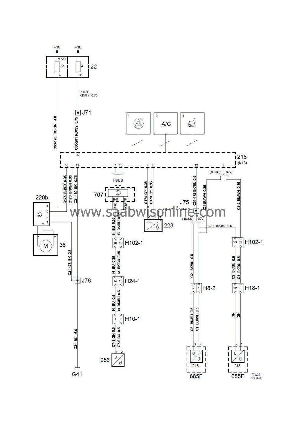
22
|
Electrical centre, dashboard,
on short end of dashboard by LH door
|
4
23
|
|
36
|
Motor, ventilation fan
on the underside of the fan housing
|

|
|
216
|
ACC control module
centre of the dashboard
|

|
|
218
|
Temperature sensor, cabin air,
in front roof console
|

|
|
220b
|
Control unit, ventilation fan, ACC,
on the fan motor housing
|

|
|
223
|
Sun sensor,
directly above the dashboard
|

|
|
286
|
Temperature sensor, outdoor air,
in the centre of the front spoiler
|

|
|
685F
|
Unit, roof lamp, front,
in the roof by the windscreen
|

|
|
707
|
Body control module, BCM,
in the dashboard's main fuse box
|

|
|
|
8-pin connectors
|
|
|
H8-2
|
Grey connector in the right A-pillar by the windscreen.
|

|
|
|
10-pin connectors
|
|
|
H10-1
|
LH side of the front spoiler
|

|
|
|
18-pin connector
|
|
|
H18-1
|
In front roof lamp unit
|

|
|
|
24-pin connector
|
|
|
H24-1
|
Black connector in front of the battery under the structural member.
|

|
|
|
102-pin connector
|
|
|
H102-1
|
Under the left A-pillar
|

|
|
|
Crimps
|
|
|
J71
|
LHD:
Approx. 50 mm from branching of column integration module towards grounding point G41
RHD:
Approximately 50 mm from grounding point G43 branching point towards the radio
|

|
|
J75
|
LHD:
Approx. 180 mm from branching of grounding point G41 towards grounding point G43
RHD:
Approx. 140 mm from the light switch branching point towards the CIM
|

|
|
J76
|
LHD:
Approximately 160 mm from branching of radio towards the ACC control module
RHD:
Approximately 40 mm from branching of grounding point G43 towards the ACC control module
|

|
|
|
Grounding points
|
|
|
G41
|
In the instrument space to the right of the knee member
|

|


