|
No.
|
Name
Location
|
Illus.
|
|
|
Components
|
|
|
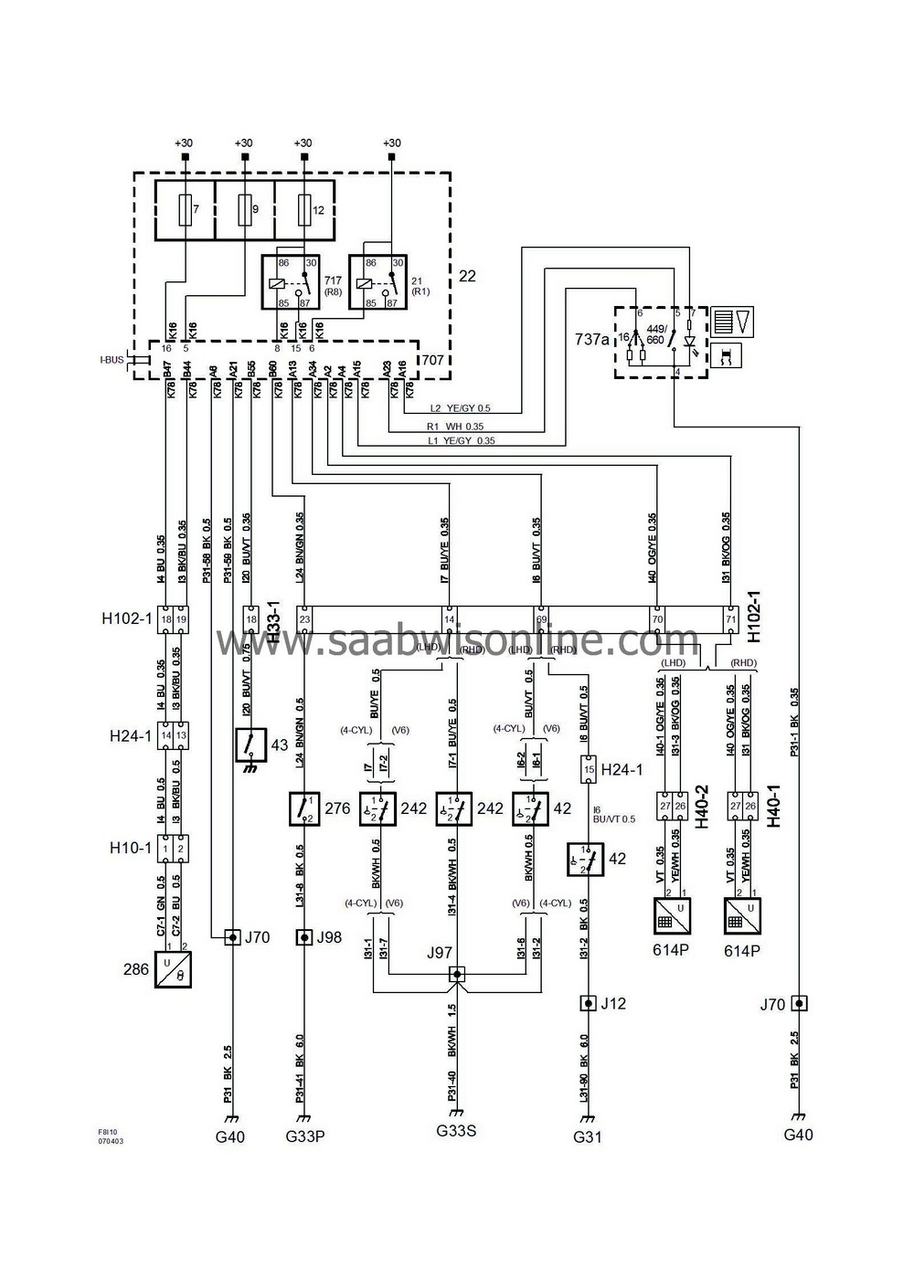
16
|
Rheostat, instrument illumination,
integrated in switch panel, (737a), on dashboard next to main instrument unit
|

|
|
21
|
Relay, +54,
in fuse box in the dashboard
|

|
|
22
|
Main fuse box, dashboard,
on the short side of the dashboard by the left door
|
7
9
12
|
|
42
|
Brake fluid level switch,
on brake fluid reservoir
|

|
|
43
|
Handbrake switch
under floor console by handbrake
|

|
|
242
|
Coolant level switch,
in coolant expansion tank
|

|
|
276
|
Bonnet switch, anti-theft alarm,
behind the battery's positive pole
|

|
|
286
|
Ambient air temperature sensor,
in centre of the front spoiler
|

|
|
449
|
Switch, TCS,
integrated in switch panel, (737a), on dashboard next to main instrument unit
|

|
|
614P
|
Loaded front passenger seat cushion sensor
in passenger seat cushion
|

|
|
660
|
ESP switch,
integrated in switch panel, (737a), on dashboard next to main instrument unit
|

|
|
707
|
Body Control Module.
in fuse box in the dashboard
|

|
|
717
|
Interior lighting relay,
in fuse box in the dashboard
|

|
|
737a
|
Switch panel,
on instrument panel next to main instrument unit
|

|
|
|
10-pin connector
|
|
|
H10-1
|
On left-hand side of front spoiler
|

|
|
|
24-pin connector
|
|
|
H24-1
|
Black connector in front of the battery under the left-hand structural member
|

|
|
|
33-pin connector
|
|
|
H33-1
|
Black connector on the console to the left of the ignition switch
|

|
|
|
40 pin connector
|
|
|
H40-1
|
Under left-hand seat
|

|
|
H40-2
|
Under RH seat
|

|
|
|
102-pin connector
|
|
|
H102-1
|
Under left A-pillar
|

|
|
|
Crimp connections
|
|
|
J12
|
Approx. 130 mm from branching of grounding point G31 towards left headlamp
|

|
|
J68
|
LHD:
Approx. 120 mm from branching of column integration module towards grounding point G41
RHD:
Approx. 40 mm from branching of switch panel (737a) towards grounding point G41
|

|
|
J70
|
LHD:
Approx. 190 mm from branching point light switch unit towards the column integration module
RHD:
Approx. 150 mm from grounding point G40 towards grounding point G41
|

|
|
J97
|
4D/5D:
Approx. 200 mm from branching of grounding point G33P/S toward the left rear door
CV:
Approx. 70 mm from branching point grounding point G33P/S towards the LH rear door
|

|
|
J98
|
4D/5D:
Approx. 250 mm from branching of grounding point G33P/S toward the left rear door
CV:
Approx. 120 mm from branching point to grounding point G33P/S towards the LH rear door
|

|
|
|
Grounding points
|
|
|
G31
|
In the engine bay on the side plate above the right wheel housing
|

|
|
G33P
|
On the floor below the LH A-pillar (black tape)
|

|
|
G33S
|
On the floor below the left A-pillar
|

|
|
G40
|
In the instrument well to the left of the knee member
|

|


