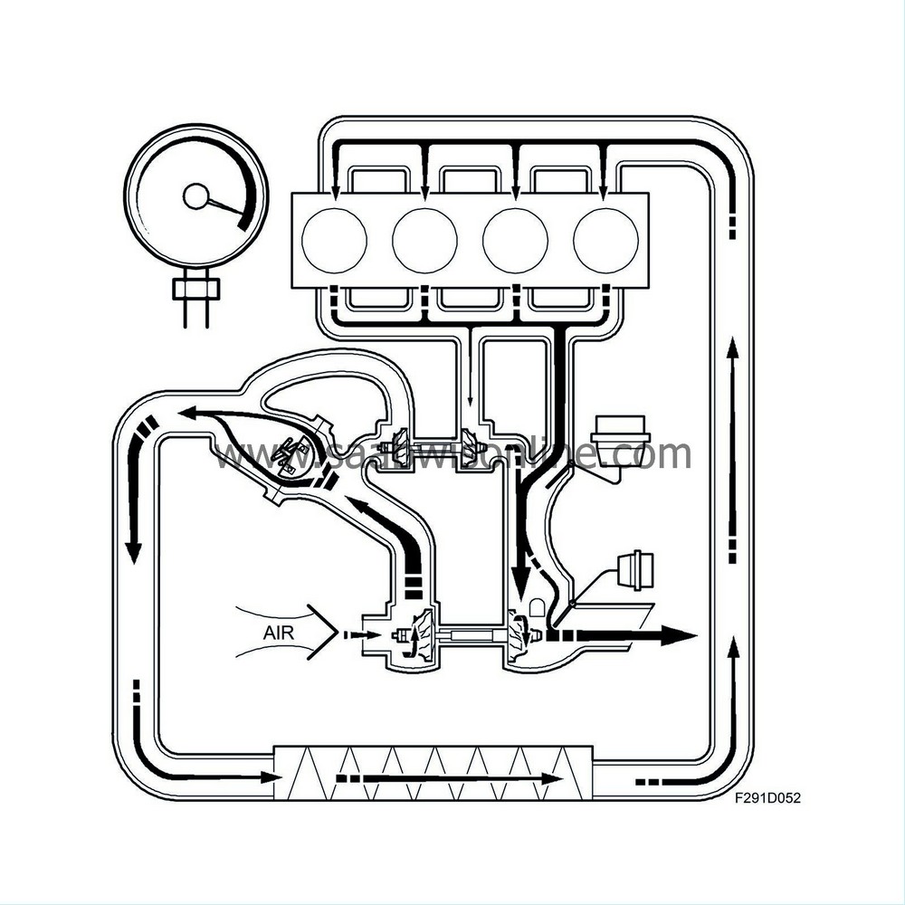
Detailed description
| Detailed description |
General
The engine uses a VNT (Variable Nozzle Turbine) turbocharger. This means the turbine can be adjusted by changing the position of a number of vanes located in the exhaust flow just ahead of the turbine wheel. In this way, the turbine speed can be controlled so that the turbocharger provides the air mass required for the engine to deliver the desired torque with low emissions.If there are only low amounts of exhaust (light engine load/low engine speed), the vane opening will be relatively small. This gives a high speed to the flow of exhaust against the turbine wheel so that the speed of the turbine wheel is also relatively high. The turbocharger will then deliver a relatively large contribution, which in turn means that a larger amount of fuel can be injected to give a high engine torque.
The opening of the vanes must be regulated to suit the prevailing running conditions, however. As a rule, when the amount of exhaust increases (high engine speed/high engine load), the vanes will open up. Otherwise, the turbine speed would increase too much and damage the turbocharger and engine and the boost pressure would be too high with high turbine pressure. The turbocharger must therefore be regulated in order to suit the engine's air requirements for each particular situation. The vane opening is affected by a vacuum box controlled by ECM via a solenoid valve.
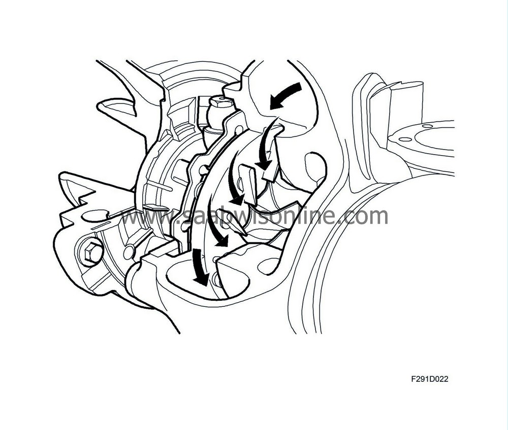
Vanes, closed position
For low exhaust flow (low engine speed / low engine load) the vane opening will be small. The speed of the exhaust gas and its angle to the turbine wheel is such that the turbine speed is high in relation to the amount of exhaust passing the turbine.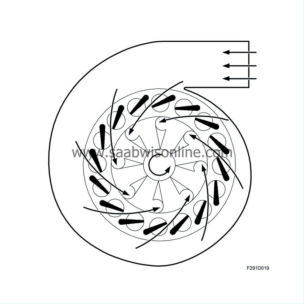
Vanes, open position
For high exhaust flow (high engine speed / high engine load) the vane opening is large. The speed of the exhaust gas and its angle to the turbine wheel is such that the turbine speed is low in relation to the amount of exhaust passing the turbine.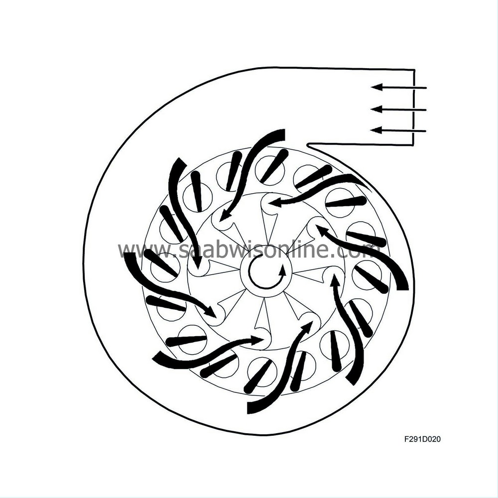
Diaphragm box, VNT
The diaphragm box is used to change the position of the vanes. It is controlled by vacuum from a vacuum tank via a solenoid valve. A coil spring in the diaphragm box keeps the vanes fully open whereas the vacuum acts in the opposite direction, i.e. closing the vanes. By controlling the vacuum to the diaphragm box, the position of the vanes can be varied. This is done with the help of a PWM controlled solenoid valve controlled by ECM.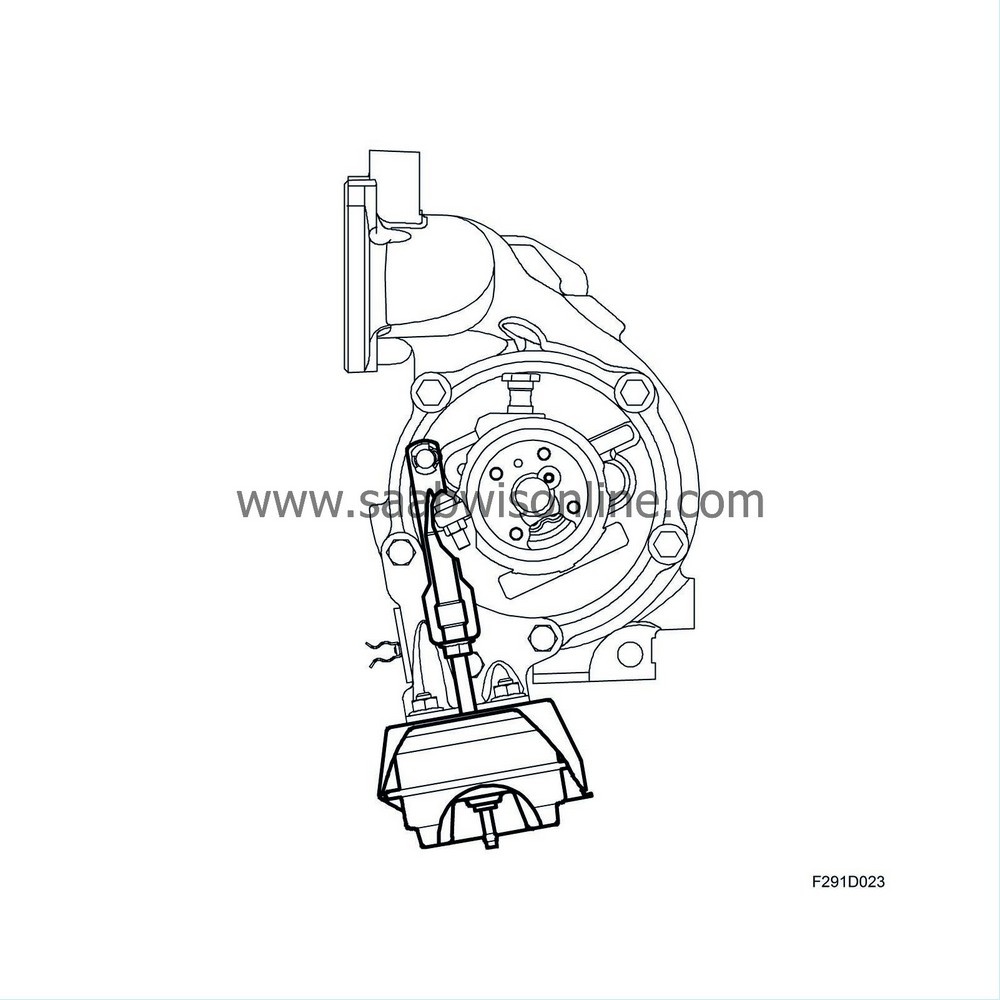
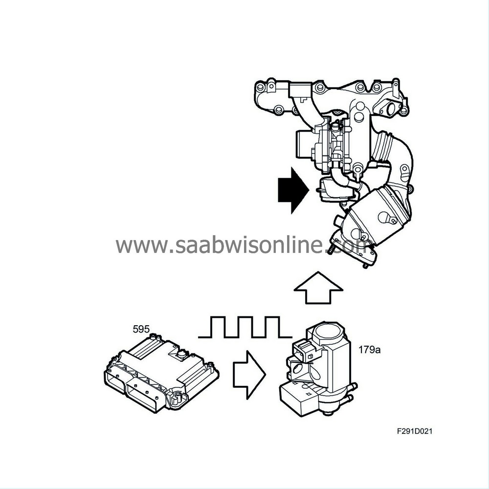
VNT solenoid valve
The solenoid valve is controlled by the engine control module via a PWM signal that opens the valve so that the desired vacuum is obtained to the diaphragm box. Through the combination of spring force in the diaphragm box and the vacuum, the vanes can be adjusted to any position between closed and open.
Lubrication
The turbine shaft rotates at a very high speed and is precisely balanced together with the turbine and compressor wheels. The shaft is supported in a fixed plain bearing bushing, which requires a large flow of oil through it so that the shaft is floating on a film of oil when it rotates. The oil comes from the engine's lubricating system through a special oil line. The return oil passes to the engine sump. The seal between the shaft and the bearing housing comprises rings similar to piston rings, which are located in a groove in the shaft.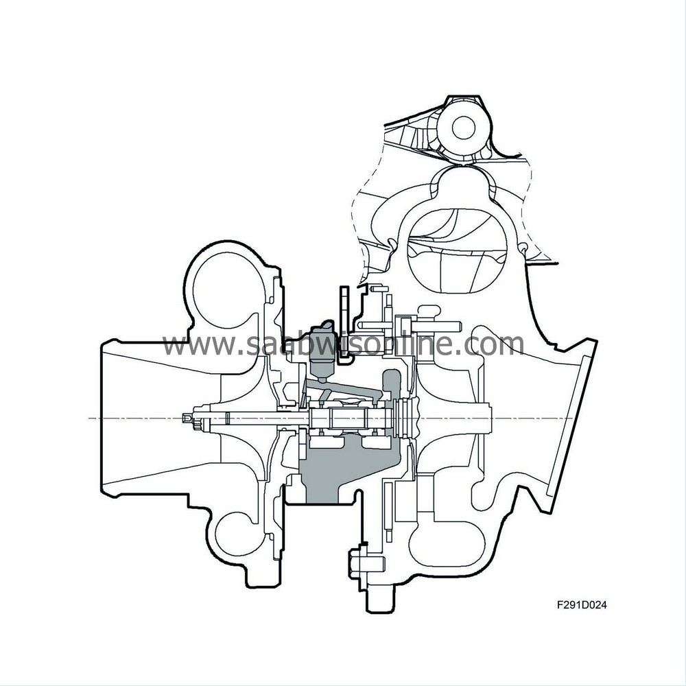
Exhaust manifold
The exhaust manifold is integrated in one unit with the turbine housing. There is an outlet for the EGR on the exhaust manifold.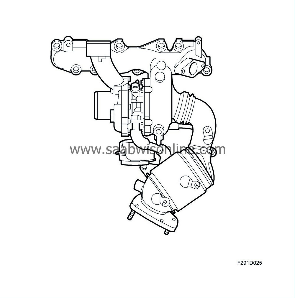
| Turbo control, Z19DTR |
General
The engine is equipped with a turbo unit consisting of two turbochargers, a check valve and two wastegates with associated diaphragm boxes. The turbo unit has a turbine housing with fixed geometry and is thus regulated by leading the exhaust gases past the turbine when there is an excess. The diaphragm boxes of the wastegates are regulated by ECM via solenoid valves, which regulate the vacuum to the diaphragm boxes.In principle, the turbo unit has three different operating modes: 1) single-stage pressure increase in the small (HPT) turbocharger's compressor, 2) two-stage pressure increase in both compressors and 3) single-stage pressure increase in the large (LPT) turbocharger's compressor only. The air on the compressor side is controlled by a check valve positioned parallel to the HPT's compressor.
Four different control cases for the turbo unit are explained below. To keep things simple, presume the engine is running at full load.
Control case 1: Low engine speed
The wastegates for HPT and LPT are closed. All exhaust gases are led into the HPT turbine, where they cause the turbine wheel to rotate quickly. They are then led out to the LPT turbine, where the turbine wheel begins to rotate slowly. Air is led into the LPT compressor, but there is no pressure increase. The air is led on into the HPT compressor inlet. There is a pressure increase in the HPT compressor due to the relatively high turbine speed. The charge air is led out of the compressor and on to the engine's intake manifold via the charge air cooler. At this time, the check valve connected in parallel via the HPT compressor is closed as the pressure outside of the compressor is greater than that inside.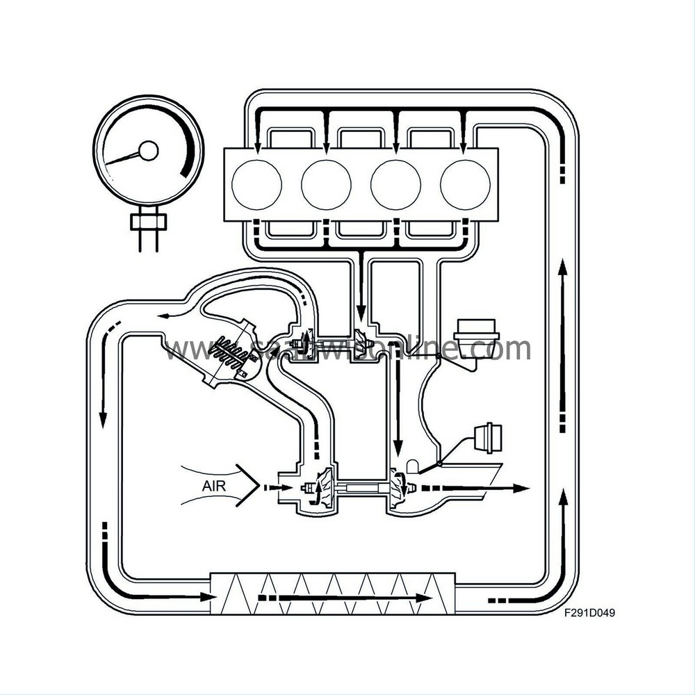
Control case 2: Intermediate range
The wastegate for HPT is partially open while the wastegate for LPT is closed. Exhaust gases are led into the HPT turbine, but some bypass it via the wastegate duct. The speed of the turbine wheel is now regulated. The exhaust gases are led out of the HPT turbine, travel via the HPT wastegate and continue to the LPT turbine, where the turbine wheel is put in motion. Its speed is so great that the LPT begins to work. Air is led into the LPT compressor, where there is a pressure increase. The air is led on into the HPT compressor inlet.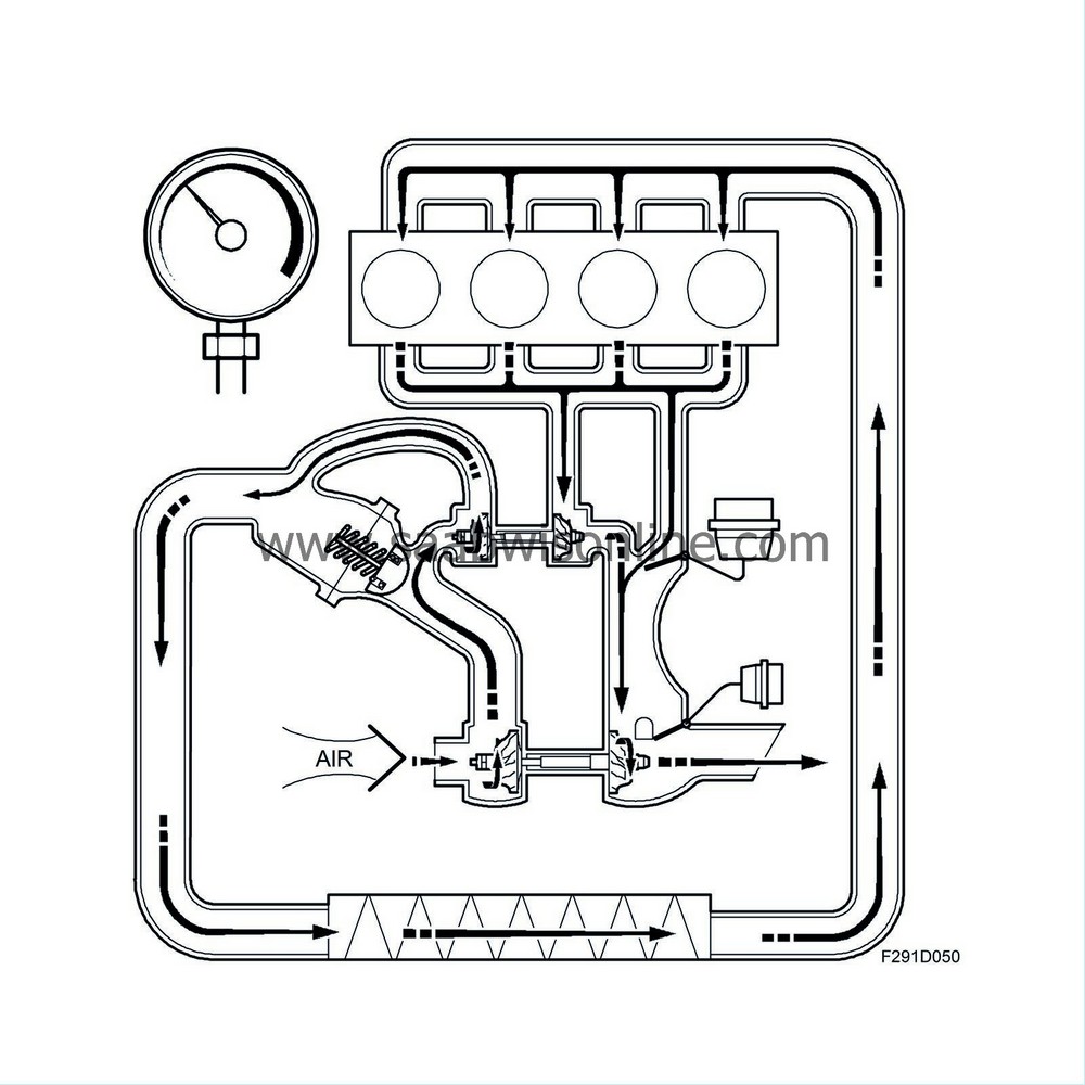
In the HPT compressor, there is another pressure increase due to the high turbine speed. The charge air is led out of the compressor and on to the engine's intake manifold via the charge air cooler. At this time, the check valve connected in parallel via the HPT compressor is closed because the pressure outside of the compressor is higher than that inside.
Control case 3: Upper-intermediate range
The wastegate for HPT is now open while the wastegate for LPT is closed. Only a small portion of the exhaust gases are led into the HPT turbine. The majority bypass the turbine via the wastegate duct. The speed of the turbine wheel is relatively low. The exhaust gases are led out of the HPT turbine, travel via the HPT wastegate and then continue to the LPT turbine, where the turbine wheel now rotates at a relatively high speed - so high that the LPT's pressure increase on the compressor side is considerably greater than that of the HPT, whose turbine speed is now low. Air is led into the LPT compressor, where all pressure increase now occurs. The air is led on to the check valve, which opens since the pressure across it is higher on the side that is linked to the HPT compressor's inlet than the pressure on the outlet side. The charge air is led on to the engine's intake manifold via the charge air cooler.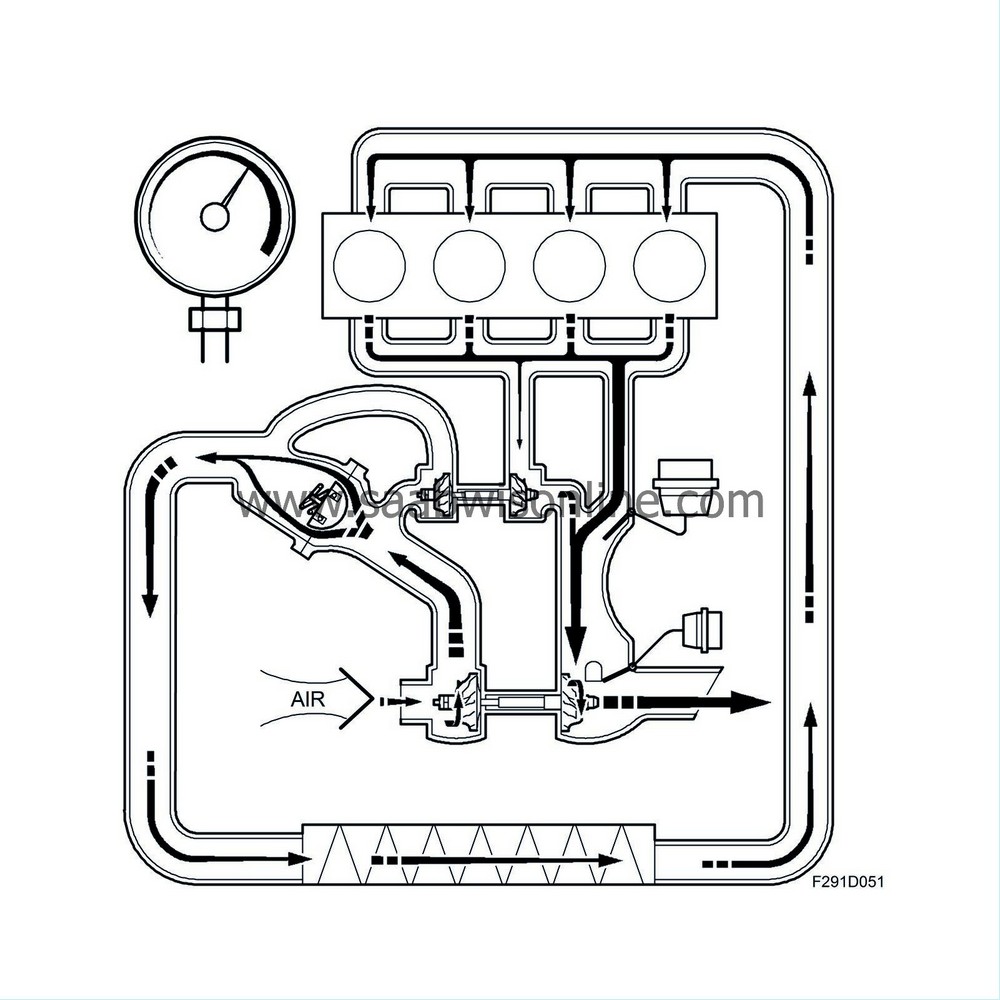
Control case 4: High engine speed (close to maximum)
This control case is similar to case 3. The only difference is that the wastegate for the LPT turbine is now fully or partially open. In other aspects, the function is the same.