Valve spring, rear
| Valve spring, rear |
| To remove |
| Important | ||
|
Store all removed valve parts in the valve stand 83 93 787. |
||
| 1. |
Remove the
Camshaft cover, rear, B284
|
|
| 2. |
Remove the spark plugs.
|
|
| 3. |
Remove the camshaft solenoid valve (695R) (A)

|
|
| 4. |
Remove the camshaft position sensor (555R) (B).
|
|
| 5. |
Rotate the engine so that the markings on the camshaft sprockets are visible (A), and the indentations align with the cylinder head. Use
EN-46105 Adjustment tool
as a gauge (the camshafts are now in their neutral position) (B).


|
|
| 6. |
Fit
EN-46106 Flywheel locking attachment
(A).

|
|
| 7. |
Mark the chain and camshaft sprocket so they can be refitted in the same position.
|
|
| 8. |
Slightly loosen the bolts holding the camshaft sprockets (A). Counterhold using an open spanner on the camshaft flats (do not remove the bolts).

|
|
| 9. |
Fit
EN-46108 -2 Fixing tool
to the camshaft chain on the intake side (B). Check that the tool grips the chain firmly.
|
|
| 10. |
Fit
EN-46108-1 Fixing tool
to the camshaft chain on the exhaust side (C). Check that the tool grips the chain firmly.
|
|
| 11. |
Tighten
EN-46108 Fixing tool
so that the chain is unloaded.
|
||||||||||
| 12. |
Remove the camshaft sprocket bolts (D).
|
|
| 13. |
Remove the sprockets from the camshafts (E).
|
|
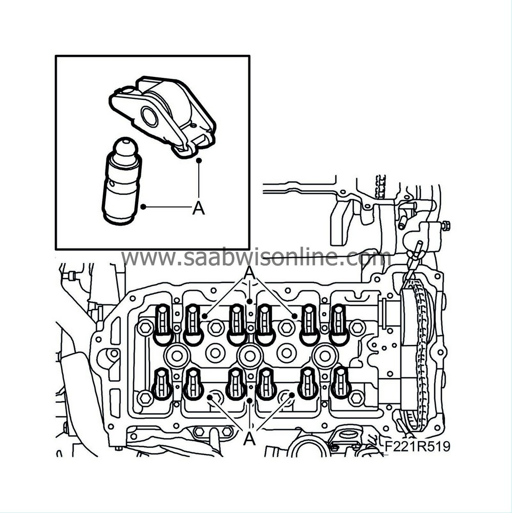
| 15. |
Lift out the camshafts (B) and note the rear marking on the camshafts.
|
|
| 16. |
Remove the roller rockers and the hydraulic adjuster elements (A). Store them in
83 93 787 Valve stand
so they do not get mixed up.
|
||||||||||
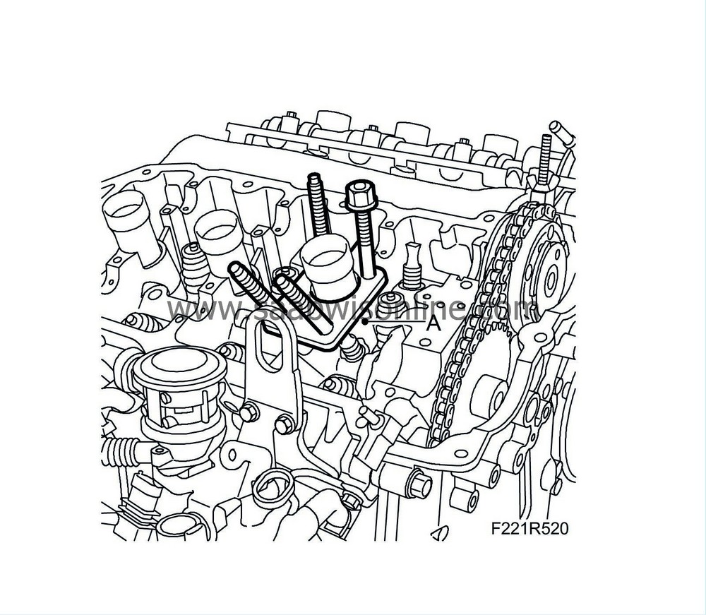
| 17. |
Fit
EN-46110-eu Valve spring tool
(A).
|
|
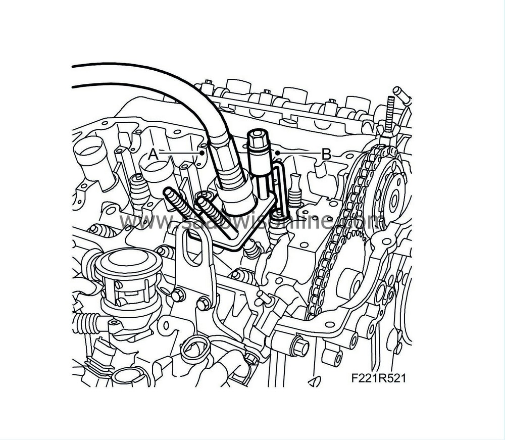
| 18. |
Fit
83 94 173 Air nipple for spark plug hole
(A). Connect compressed air and put the piston and valves under pressure.
|
|
| 19. |
Press down the valve plate (B) with
EN-46110-eu Valve spring tool
.
|
||||||||||
| 20. |
Remove the valve cone with a magnet (A).

|
|
| 21. |
Lift out the spring plate and valve spring (A).

|
|
| To fit |
| 1. |
Clean all parts and check contact surfaces and bearing surfaces for wear.
|
|
| 2. |
Fit the valve spring and spring plate (A).

|
|
| 3. |
Press down the valve plate with
EN-46110-eu Valve spring tool
.
|
|
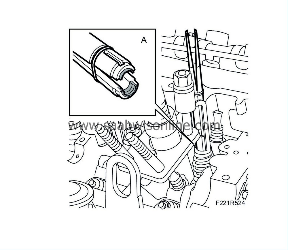
| 4. |
Fit the valve cone (A) using
EN-46117 Fitting tool
.
|
|
| 5. |
Unload the valve and remove
EN-46110-eu Valve spring tool
.
|
|
| 6. |
Disconnect the compressed air connection and remove the air nipple.
|
|
| 7. |
Position the camshafts and use
EN-46105-1 Adjustment tool
to check that the camshafts are mounted at the correct angle.
|
|
| 8. |
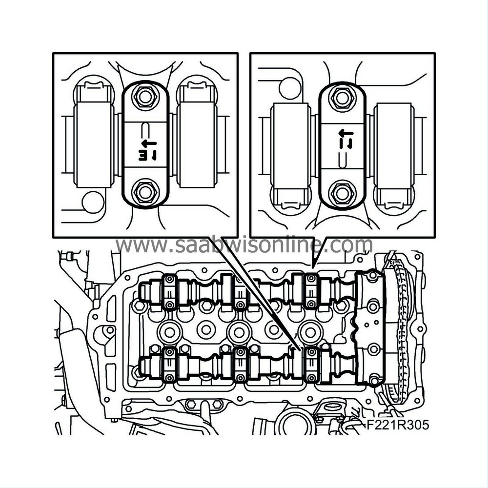
Fit the bearing caps as illustrated (markings on caps). Start where the cams point down and load the tappets.
Tightening torque 10 Nm (7 lbf ft)
|
||||||||||
| 9. |
Check that the markings (A) on the chain match the markings on the sprockets.

|
|
| 10. |
Fit the sprockets with chain on the camshafts. Tighten the bolts by hand (A).
|
|
| 11. |
Remove
EN-46108-2 Fixing tool
(B).

|
|
| 12. |
Remove
EN-46108-1 Fixing tool
(C).
|
|
| 13. |
Tighten the bolts for both camshaft sprockets, counterholding with an open spanner on the camshaft flats (D).
Tightening torque: 65 Nm (48 lbf ft) |
|
| 14. |
Remove
EN-46106 Flywheel locking attachment
.
|
|
| 15. |
Fit the camshaft position sensor (555R) using a new gasket (B).
Tightening torque 10 Nm (7 lbf ft) 
|
|
| 16. |
Fit the camshaft solenoid valve (695R) using a new seal (A).
Tightening torque 10 Nm (7 lbf ft) |
|
| 17. |
Fit the spark plugs.
|
|
| 18. |
Fit the
Camshaft cover, rear, B284
|
|


