Detailed description
| Detailed description |
| Closed crankcase ventilation |
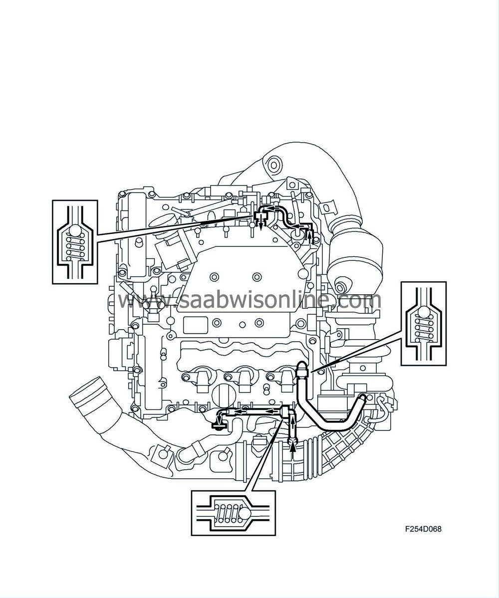
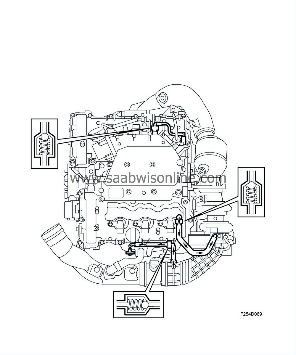
The combustion gases that pass the piston rings are collected in the crankcase and must be led out of the engine via crankcase ventilation. This is partly to prevent too high of a pressure in the crankcase and partly to lead away water vapour and hydrocarbons from the combustion. Since crankcase gases contain hydrocarbons, they may not be released into the air. They must instead be led back into the cylinders for combustion. Crankcase is therefore a closed system. Both camshaft covers have an oil separator.
When driving with a low engine load, pressure in the engine's intake manifold is low. Fresh air is supplied to the crankcase via the dipstick tube. Crankcase gases are sucked out via the rear camshaft cover.
| Catalytic converters |
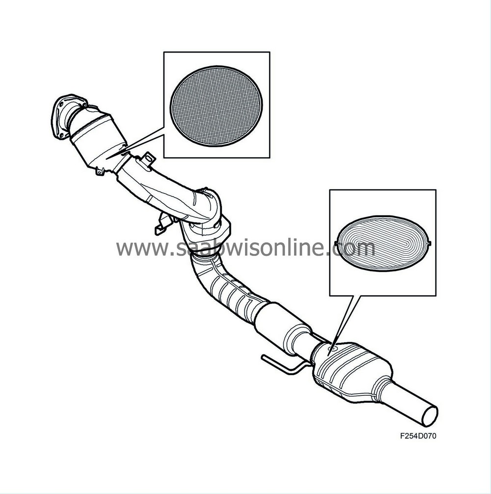
The car is equipped with two catalytic converters. One is located just downstream of the turbine outlet while the other is located under the car. The front catalytic converter has a ceramic carrier while the carrier of the rear one is metallic.
The catalytic converter has a high conversion rate within a very narrow range. If the fuel-air mixture is not kept within this range, one or more gases will inevitably exceed the permitted values. A closed loop fuel injection system guarantees that the fuel-air mixture remains correct.
Assuming that the closed loop fuel injection system gives optimum fuel-air mixture conditions, the catalytic converter reduces nitrous oxides (NO x ) and oxidises carbon monoxide (CO) and hydrocarbons (HC). The end products are carbon dioxide (CO 2 ), water (H 2 O) and nitrogen (N 2 ).
The condition for a catalytic converter to reduce emissions is that a car is only filled with unleaded petrol. This is because lead will destroy the active elements of the catalytic converter.
| Secondary air injection |
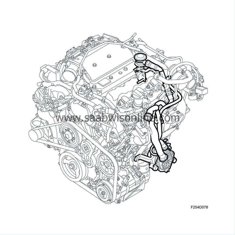
In order to get the catalytic converters to work as quickly as possible after a cold start and thereby maintain good emission values, the surrounding air is pumped into the front exhaust manifold by means of a secondary air injection pump. The oxygen in the air then initiates a chemical reaction together with the CO and HC compounds, whereby heat is generated.
Air is led via a pipe system to the exhaust manifold, which distributes the air to the respective exhaust port. The air is led via short ducts in the cylinder heads. These ducts lead into the respective exhaust port.
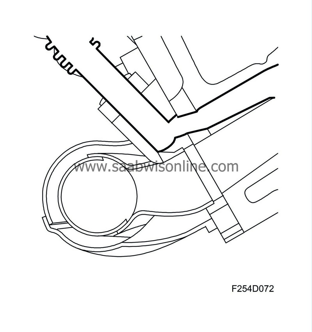
More fuel is added in order to compensate for the extra air. This extra fuel is added adaptively to the calculated fuel quantity. ECM calculates the extra amount of fuel using a matrix.
In order to further increase heat development, ignition timing is displaced to a later value, approx. 8-10°C after top dead centre.
The secondary air injection pump starts upon engine start provided that the charge air temperature and coolant temperature are within their limit values.
Before the secondary air injection pump starts, the engine can perform a number of combustions. The delay depends on coolant temperature.
The secondary air injection pump will continue to run for another few combustions after the system has stopped requesting it. This is to avoid unnecessary hydrocarbon emissions once the functions have been deactivated.
In order to avoid exhaust gases leaking back through the secondary air system there is a check valve in the system. Air is allowed to flow from the secondary air injection pump to the exhaust manifold but exhaust gases are not allowed to flow towards the pump.
A pressure sensor has been introduced for diagnostic purposes.
| Wideband lambda control |
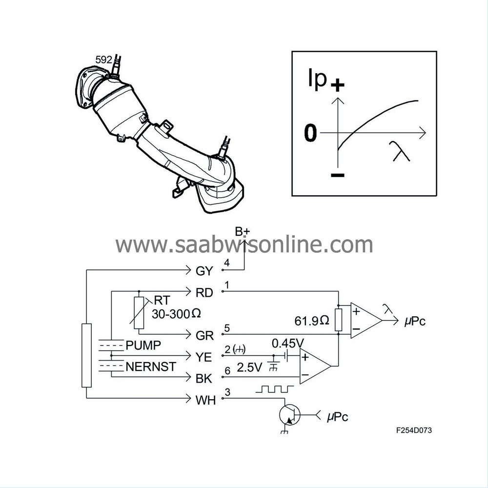
Control is based on the principle of a heated narrow band sensor (consisting of a reference cell and a Nerst cell) connected to a pump cell. The cells are made of ZrO2 with porous, platinum electrodes.
The cells are located at 10-50 micro metres intervals with the gaps linked to the surrounding exhaust gases through a small hole.
The pump cell pumps oxygen from the measurement gap to the surroundings if the exhaust gases have a lambda value over lambda=1. The size of the flow through the pump cell is an indication of the oxygen content of the exhaust gases. If the exhaust gases have a high lambda value, pump flow is relatively high.
ECM controls the pump current so that the exhaust lambda in the space is always lambda = 1. Once lambda = 1 has been attained, the voltage from the measuring cell will be 450 mV, a voltage that ECM consequently tries to keep constant by varying the pump current. It is therefore the pump current that provides information on the lambda value.
The temperature of the oxygen sensor must be controlled very carefully and ECM achieves this by varying the preheating current in the heating element.


