Connector H102-1, pin/sleeve replacement
| Connector H102-1, pin/sleeve replacement |
|
|||||||
| To remove |
| 1. |
Remove
Baffle, driver
.
|
|
| 2. |
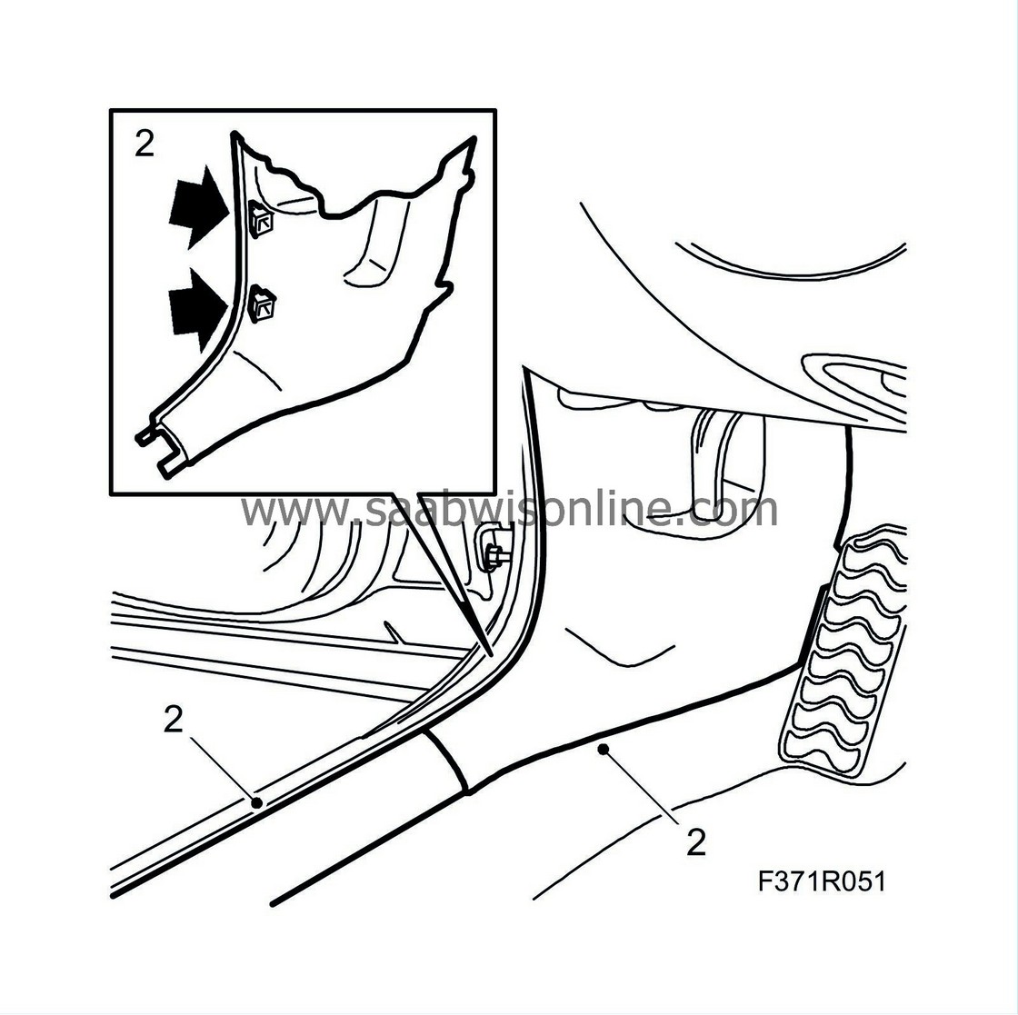
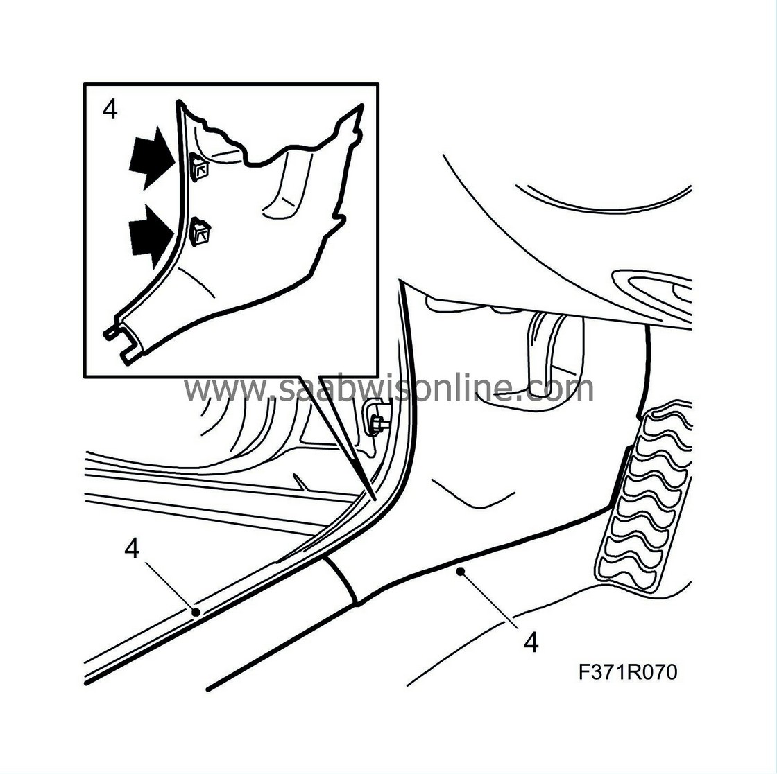
Remove the front scuff plates and the lower side panels of the A-pillars.
|
|
| 3. |
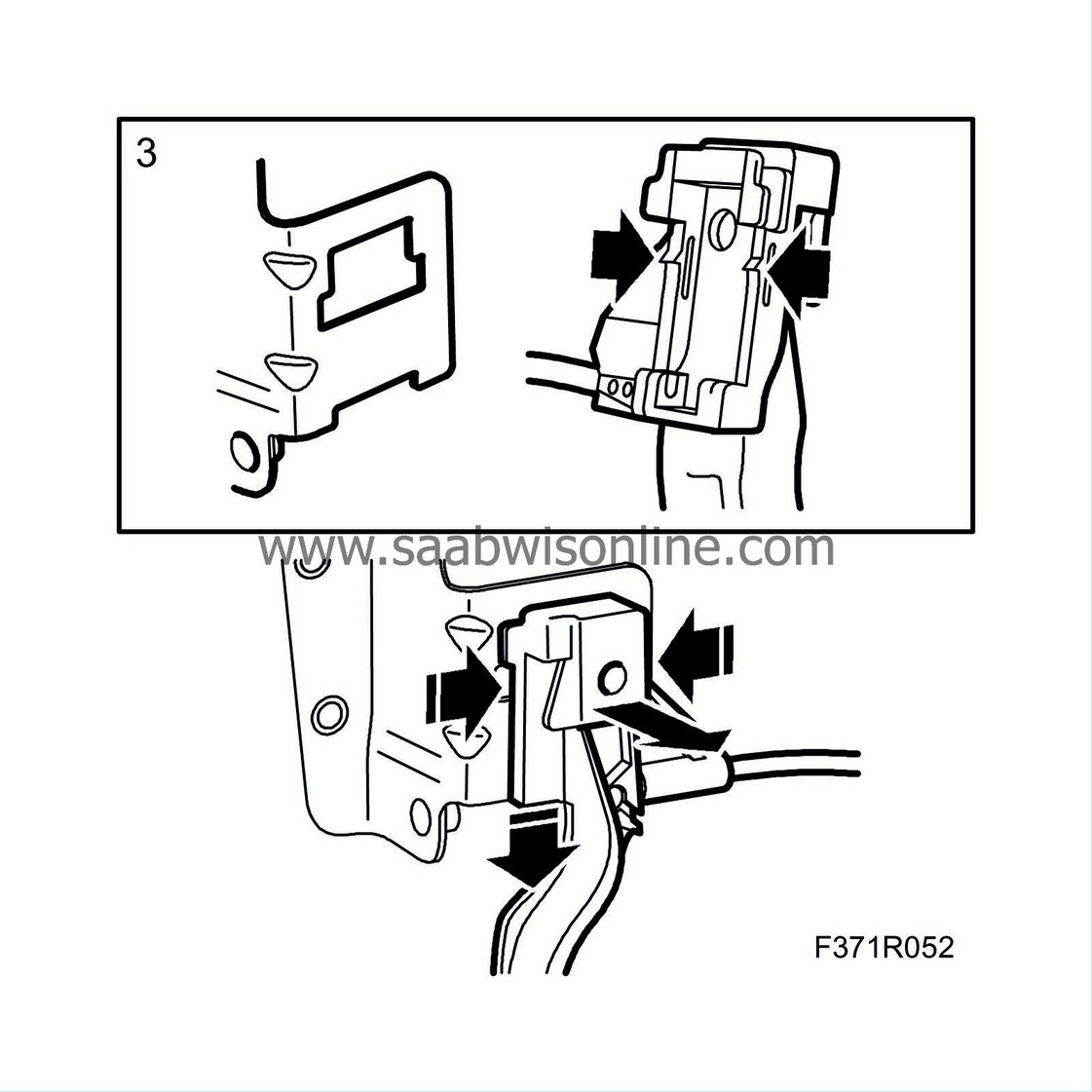
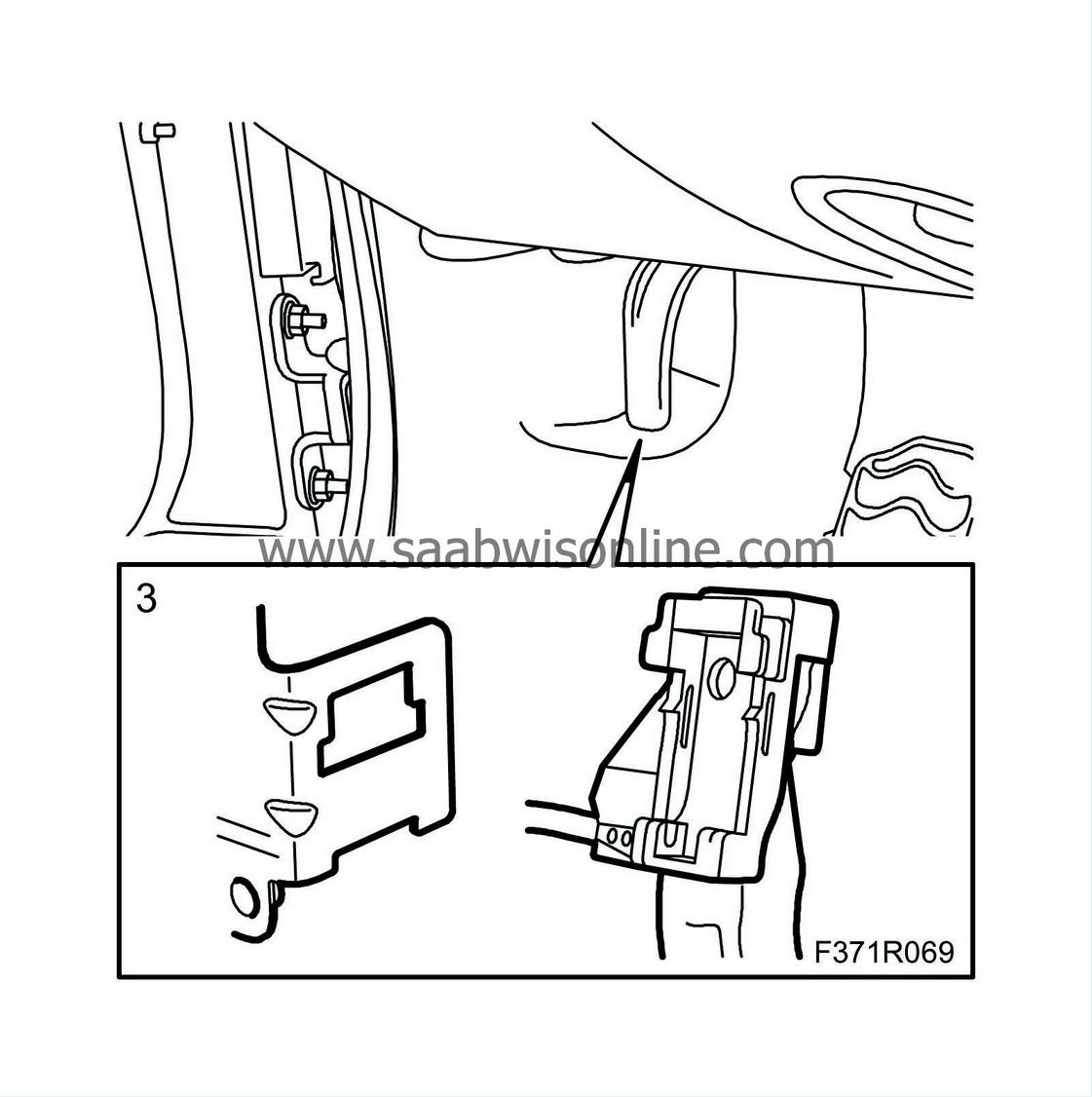
Use a screwdriver to press in the rear catches and remove the bonnet opening lever.
|
|
| 4. |
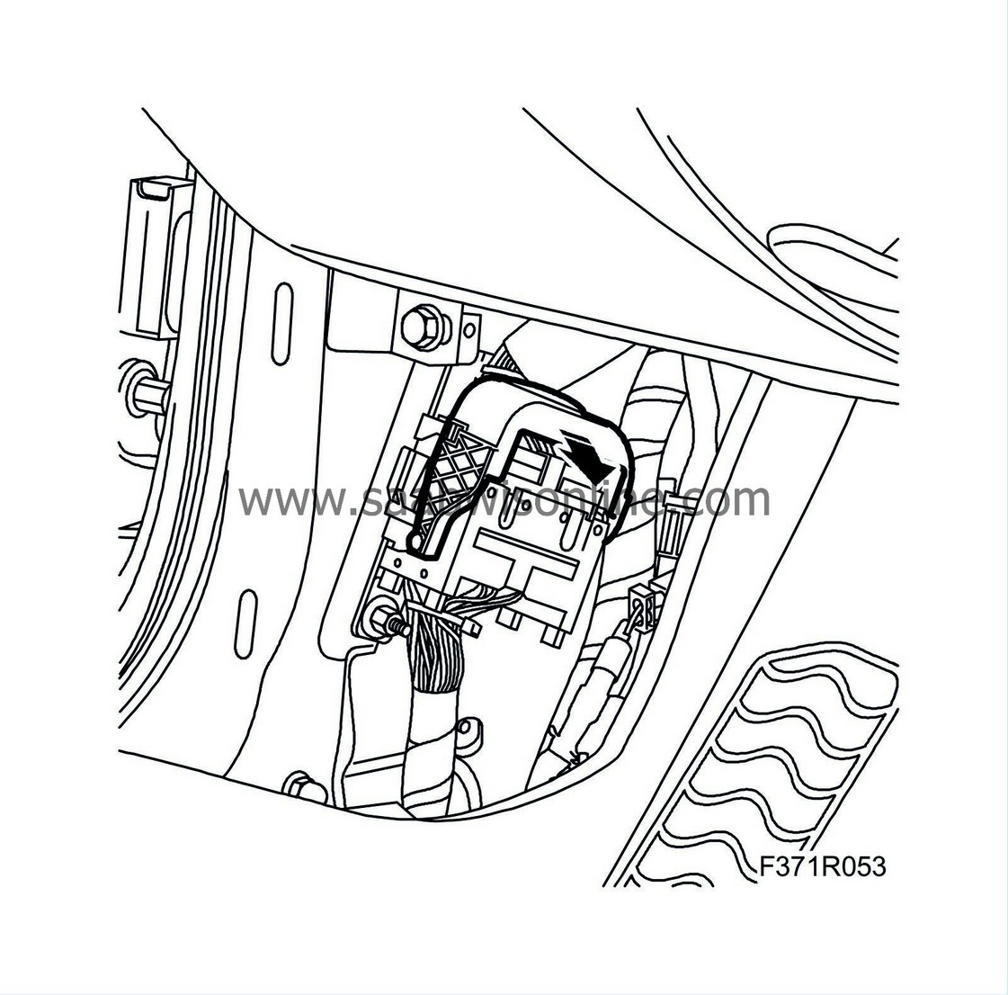
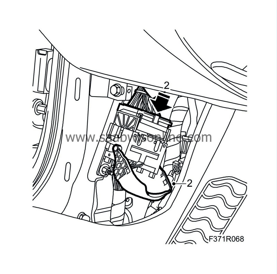
Undo the lock clamp.
|
|
| 5. |
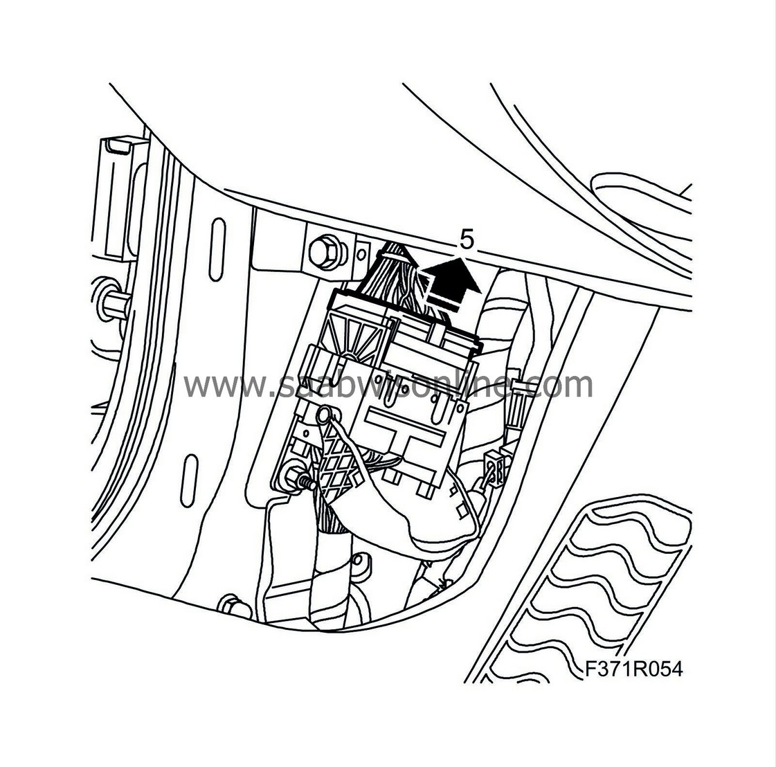
Unplug the upper (female) part of the connector.
|
|
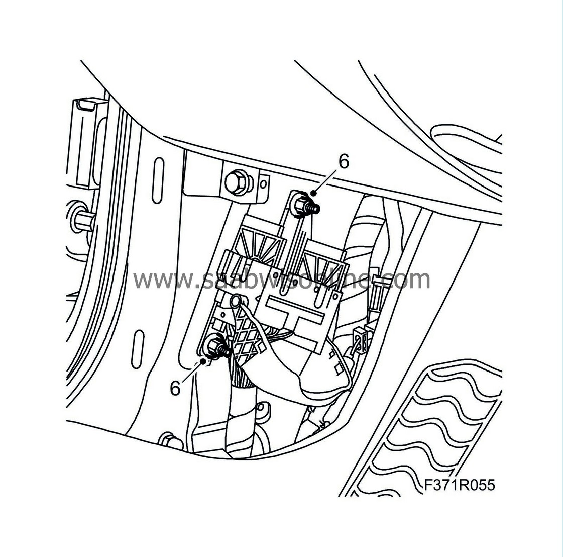
| 6. |
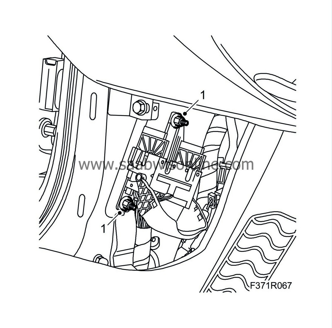
Remove the connector retaining nuts.
|
|
| Pin replacement |
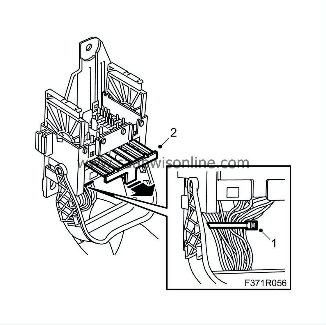
| 1. |
Cut off the cable tie.
|
|
| 2. |
Remove the secondary catch.
|
|
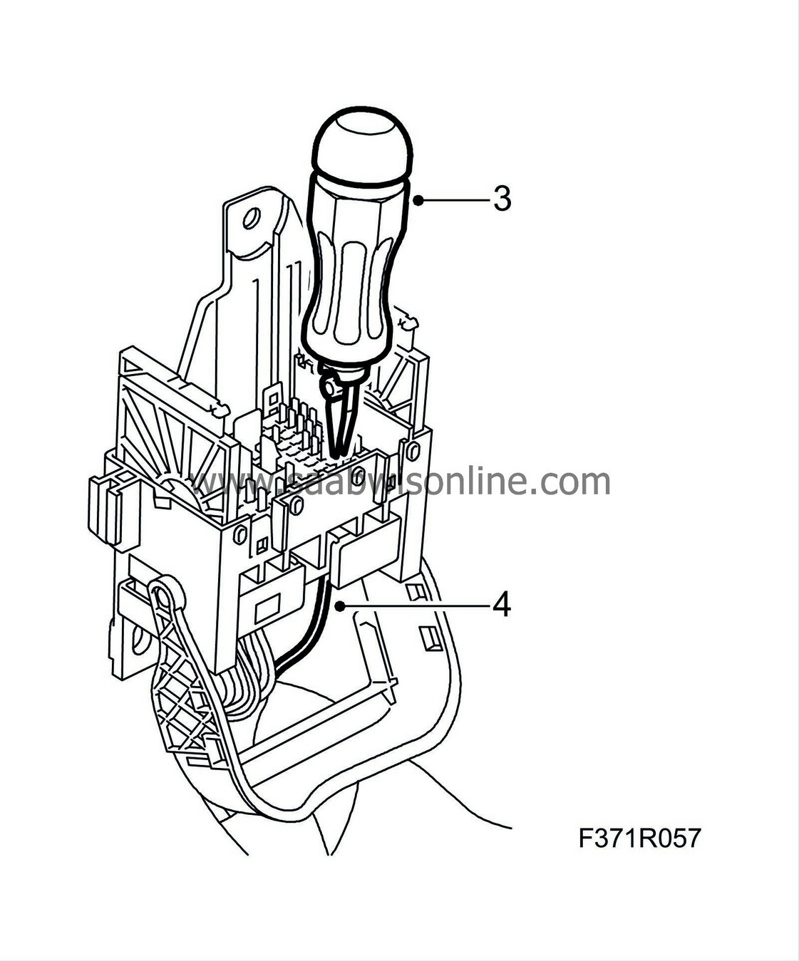
| 3. |
Undo the pin catch by pressing in the extraction tool (part no. 85 80 151).
|
|
| 4. |
Pull out the cable with the pin.
|
|
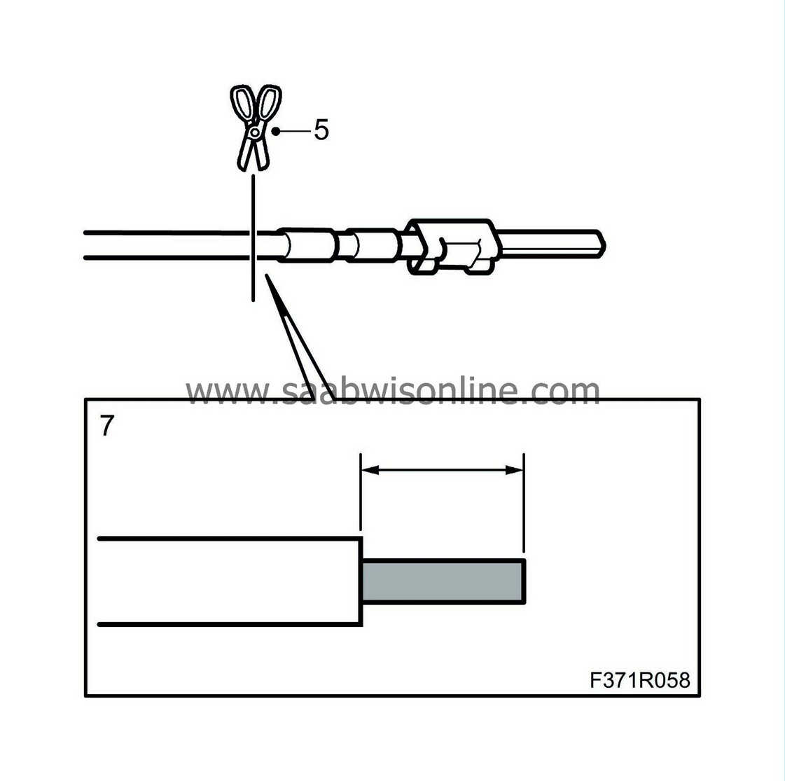
| 5. |
Cut of the lead at the pin.
|
|||||||
| 6. |
If the lead is not long enough, splice it as follows:
|
|
| 6.1. |
Strip the insulation off of the leads.
|
| 6.2. |
Fit a shrink tube with adhesive on the line.
|
| 6.3. |
Fit sleeve (0.5-1.0 mm²), using the blue pliers from 86 12 939 Toolbox, wiring harness.
|
|||||||
| 6.4. |
Place the shrink tube over the sleeve.
|
| 6.5. |
Heat the shrink tube until it is secured.
|
| 7. |
Strip 4 mm of the lead's insulation.
|
|
| 8. |
Search for the connector in the spare parts catalogue/EPC to find the part number of the pin to be used.
|
|
| 9. |
Fit the pin on the lead using olive green pliers (0.35-0.75 mm²) from 86 12 939 Toolbox, wiring harness.
|
|
| 10. |
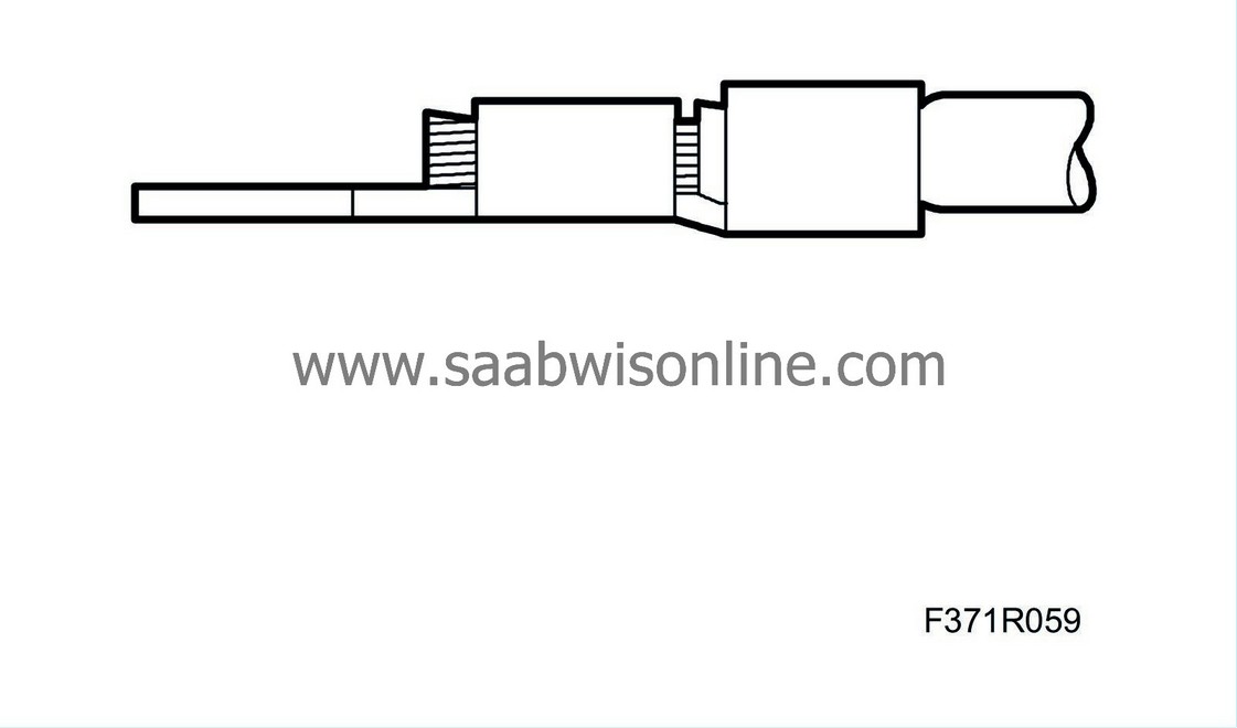
Check that the stripped lead goes through the entire clamped portion of the pin and that the insulation is properly clamped.
|
|
| 11. |
Press the pin into the connector.
|
|
| 12. |
Check that the pin is properly secured.
|
|
| 13. |
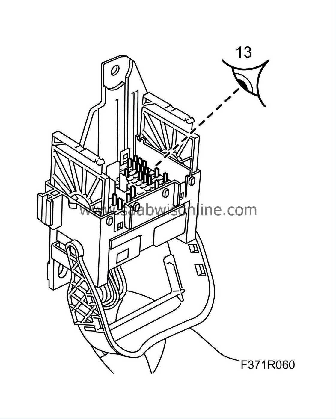
Check that the connector pins are straight.
|
|
| 14. |
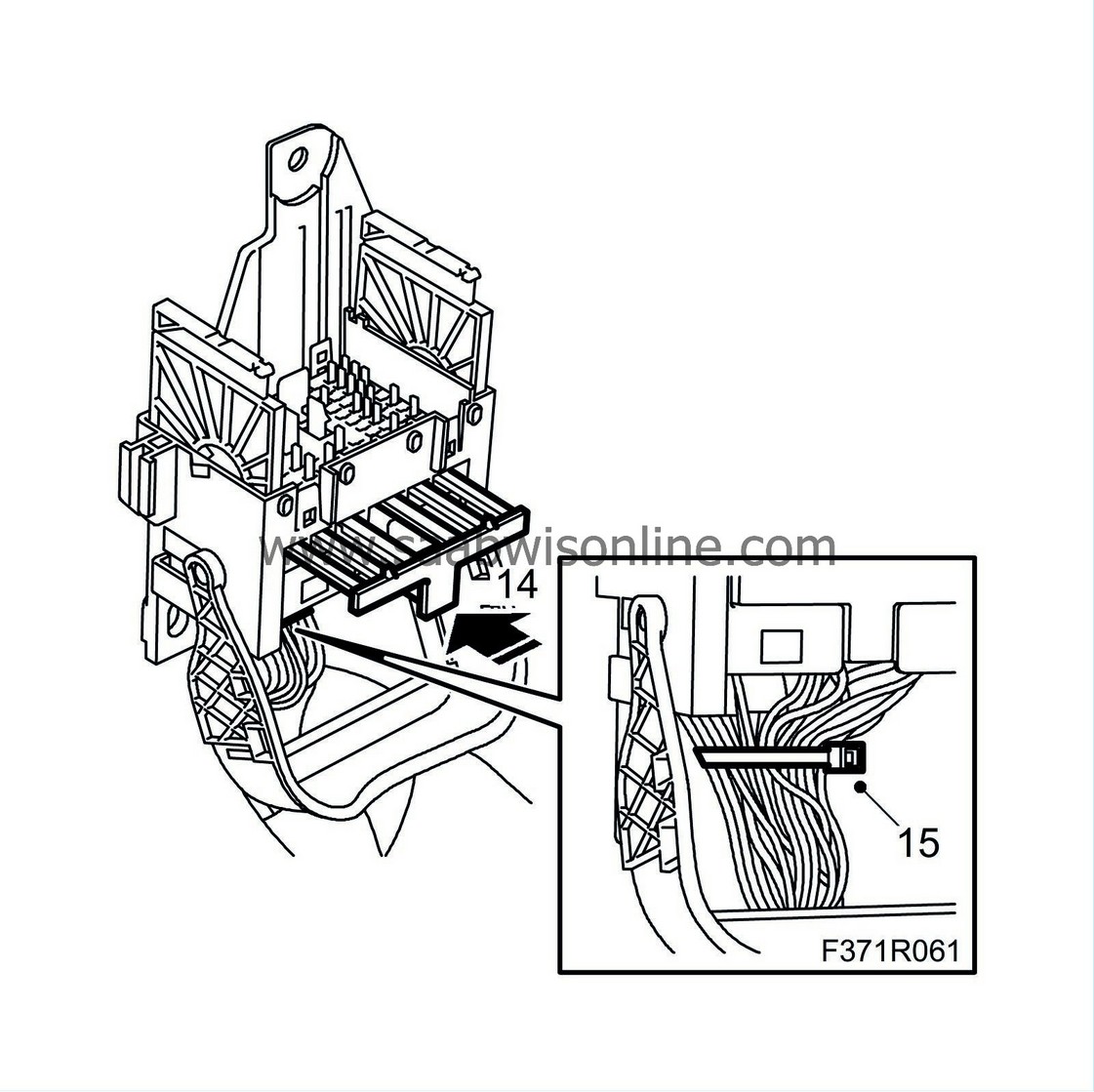
Fit the secondary catch.
|
|
| 15. |
Secure the leads with a cable tie.
|
|
| Sleeve replacement. |
| 1. |
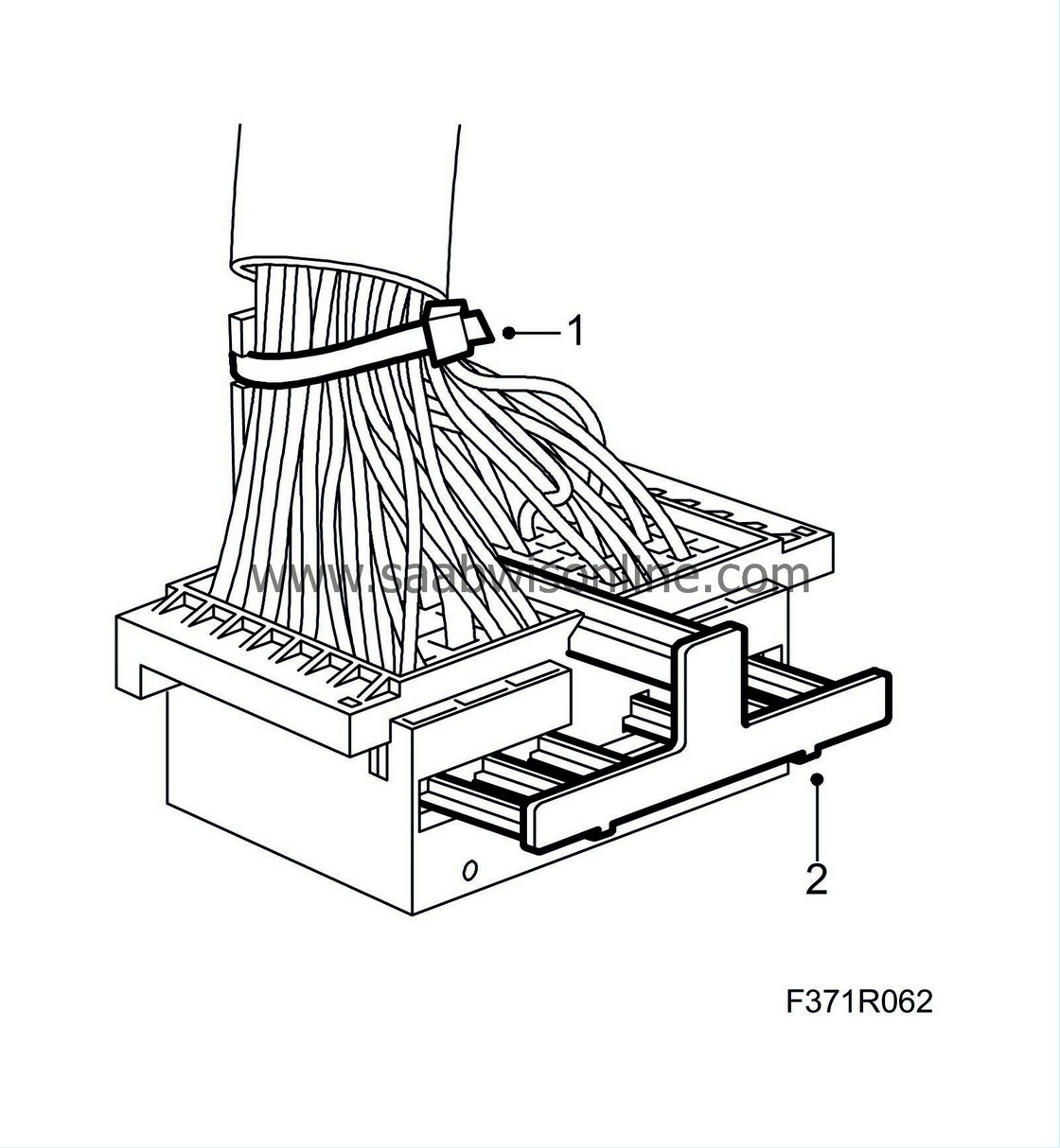
Cut off the cable tie.
|
|
| 2. |
Remove the secondary catch.
|
|
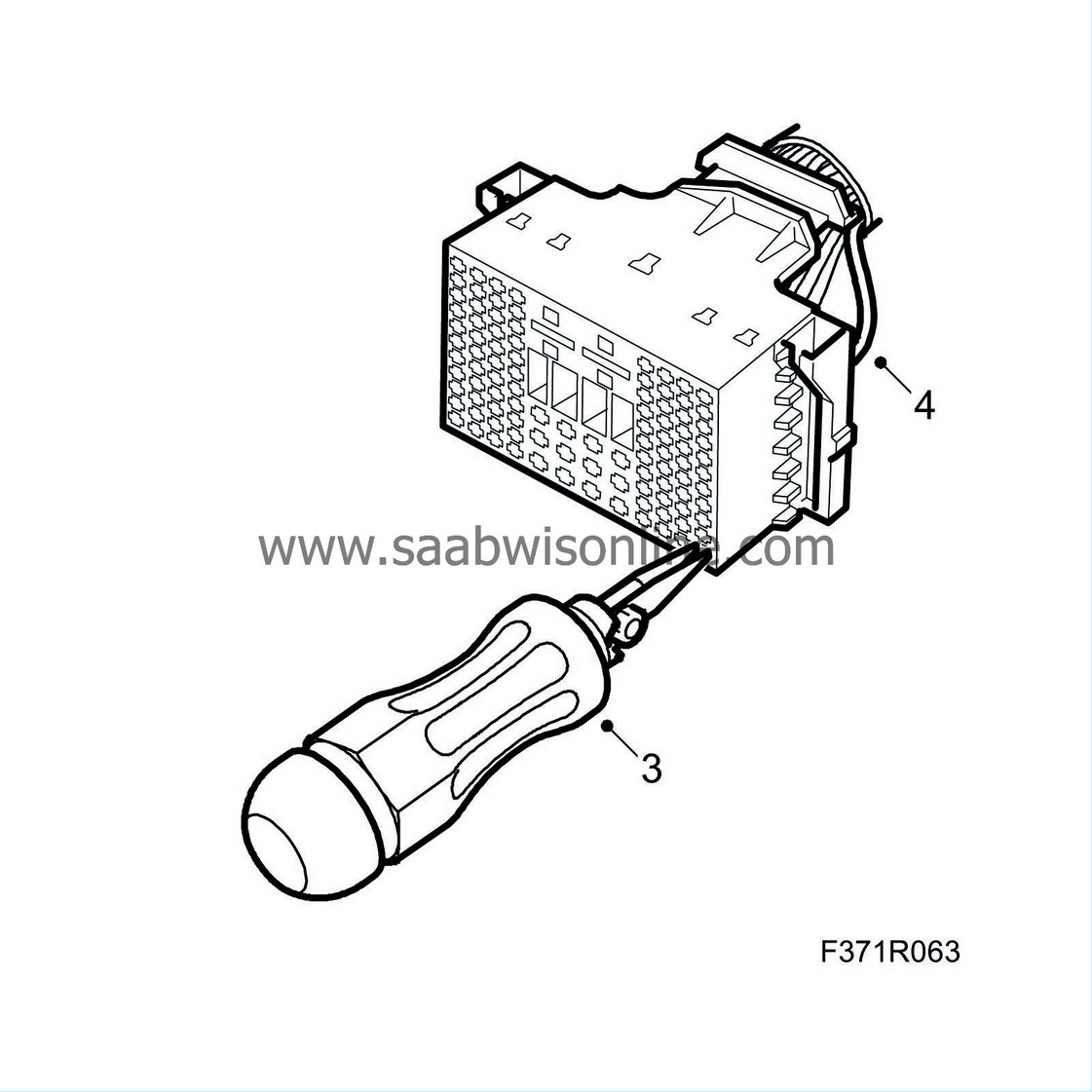
| 3. |
Undo the sleeve catch by pressing in the extraction tool (part no. 85 80 151).
|
|
| 4. |
Pull out the cable with the sleeve.
|
|
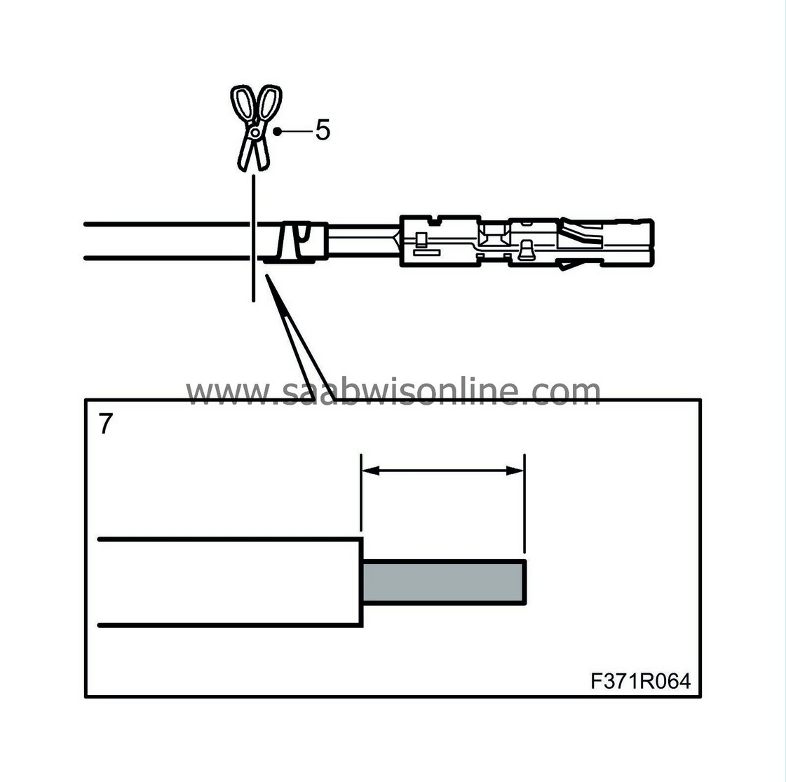
| 5. |
Cut off the lead at the sleeve.
|
|||||||
| 6. |
If the lead is not long enough, splice it as follows:
|
|
| 6.1. |
Strip the insulation off of the leads.
|
| 6.2. |
Fit a shrink tube with adhesive on the line.
|
| 6.3. |
Fit sleeve (0.5-1.0 mm²), using the blue pliers from 86 12 939 Toolbox, wiring harness.
|
|||||||
| 6.4. |
Place the shrink tube over the sleeve.
|
| 6.5. |
Heat the shrink tube until it is secured.
|
| 7. |
Strip 4 mm of the lead's insulation.
|
|
| 8. |
Search for the connector in the spare parts catalogue/EPC to find the part number of the sleeve to be used.
|
|
| 9. |
Fit the sleeve on the lead using olive green pliers (0.35-0.75 mm²) from 86 12 939 Toolbox, wiring harness.
|
|
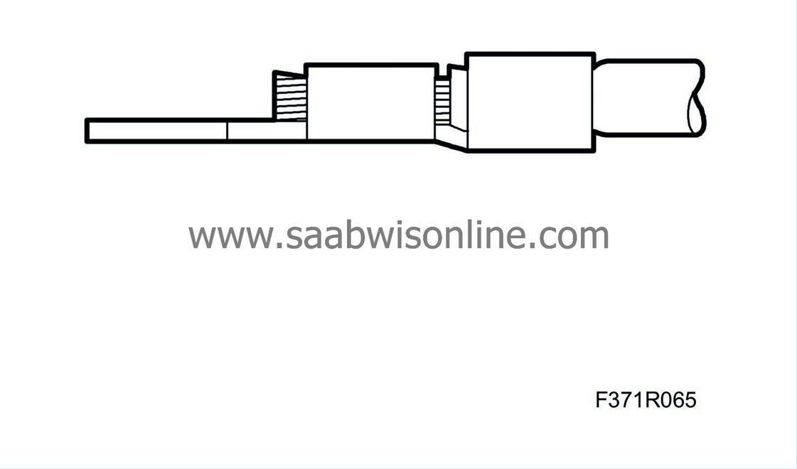
| 10. |
Check that the stripped lead goes through the entire clamped portion of the sleeve and that the insulation is properly clamped.
|
|
| 11. |
Press the sleeve into the connector.
|
|
| 12. |
Check that the sleeve is properly secured.
|
|
| 13. |
Check that the sleeve's depth of engagement is the same as the other sleeves in the connector.
|
|
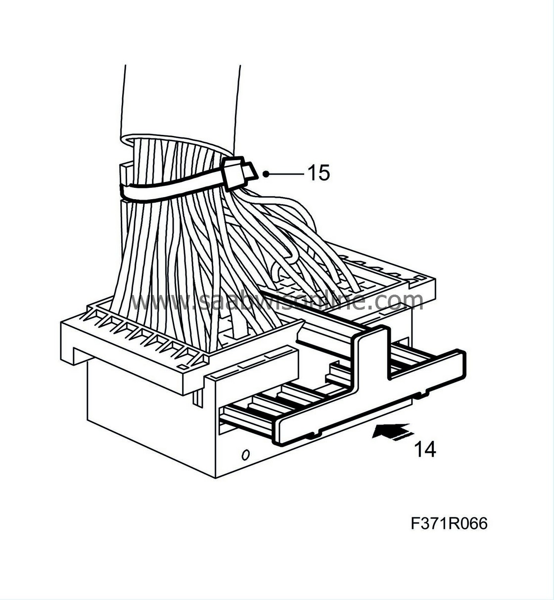
| 14. |
Fit the secondary catch.
|
|
| 15. |
Secure the leads with a cable tie.
|
|
| To fit |
| 1. |
Fit the connector.
|
|
| 2. |
Plug in the upper part of the connector and lower the lock clamp.
|
|
| 3. |
Fit the bonnet opening lever by positioning it and pressing upward.
|
|
| 4. |
Fit the front scuff plates and the lower side panels of the A-pillars.
|
|
| 5. |
Fit
Baffle, driver
.
|
|

 Warning

