TCS (382)/ESP (671) connector, changing sleeve
| TCS (382)/ESP (671) connector, changing sleeve |
| To remove |
| Important | ||
|
ESD-SENSITIVE COMPONENT |
||
|
Earth yourself by touching the car body before plugging in / unplugging components. Do not touch the component pins . Read Before removing a control module before changing a control module. |
||
| 1. |
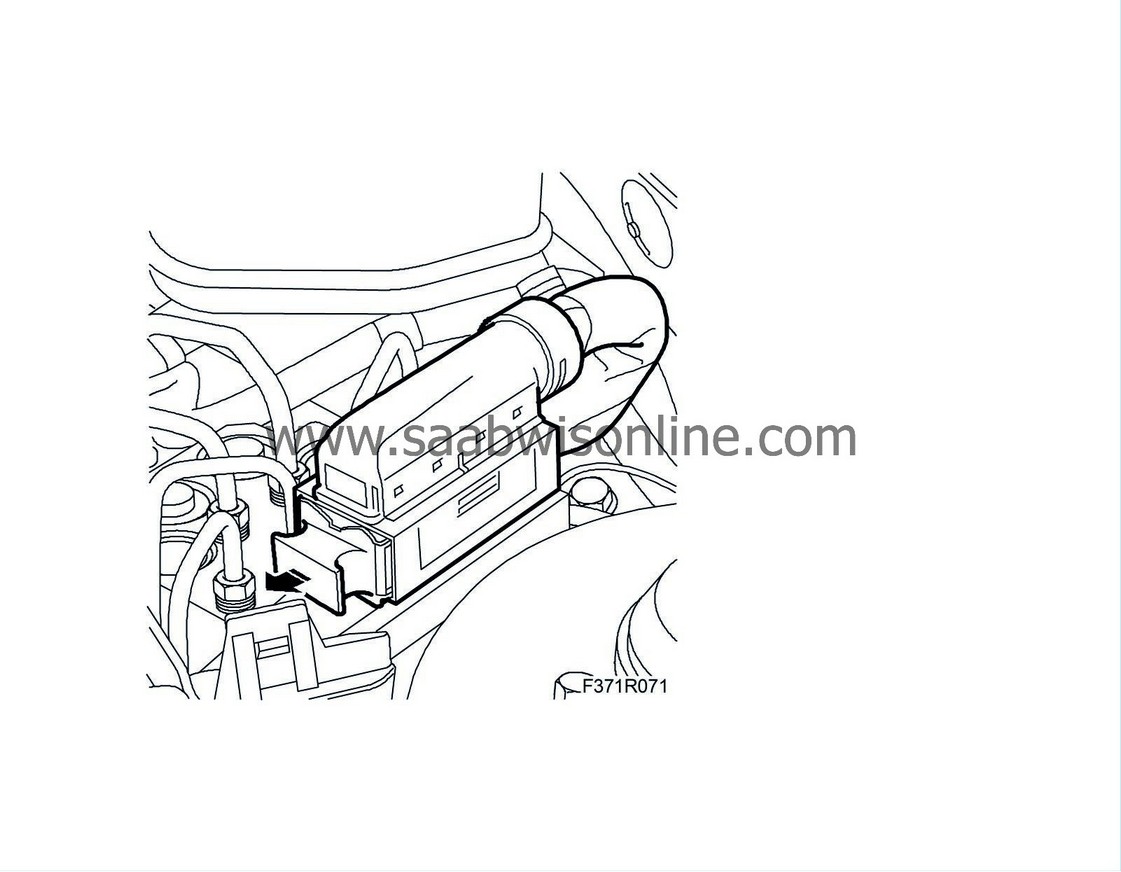
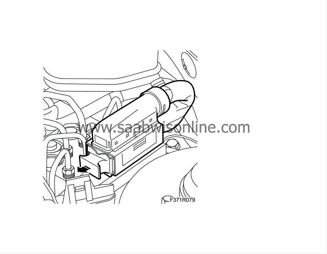
Unplug the connector.
|
|
| Changing sleeve |
| 1. |
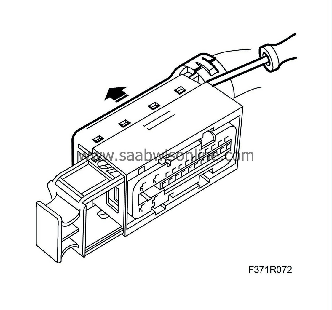
Remove the cover.
|
|
| 2. |
Cut the cable tie.
|
|
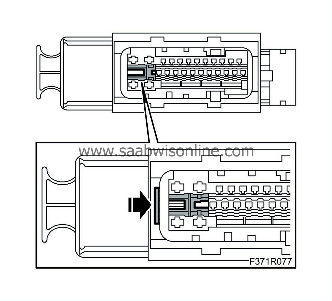
| 3. |
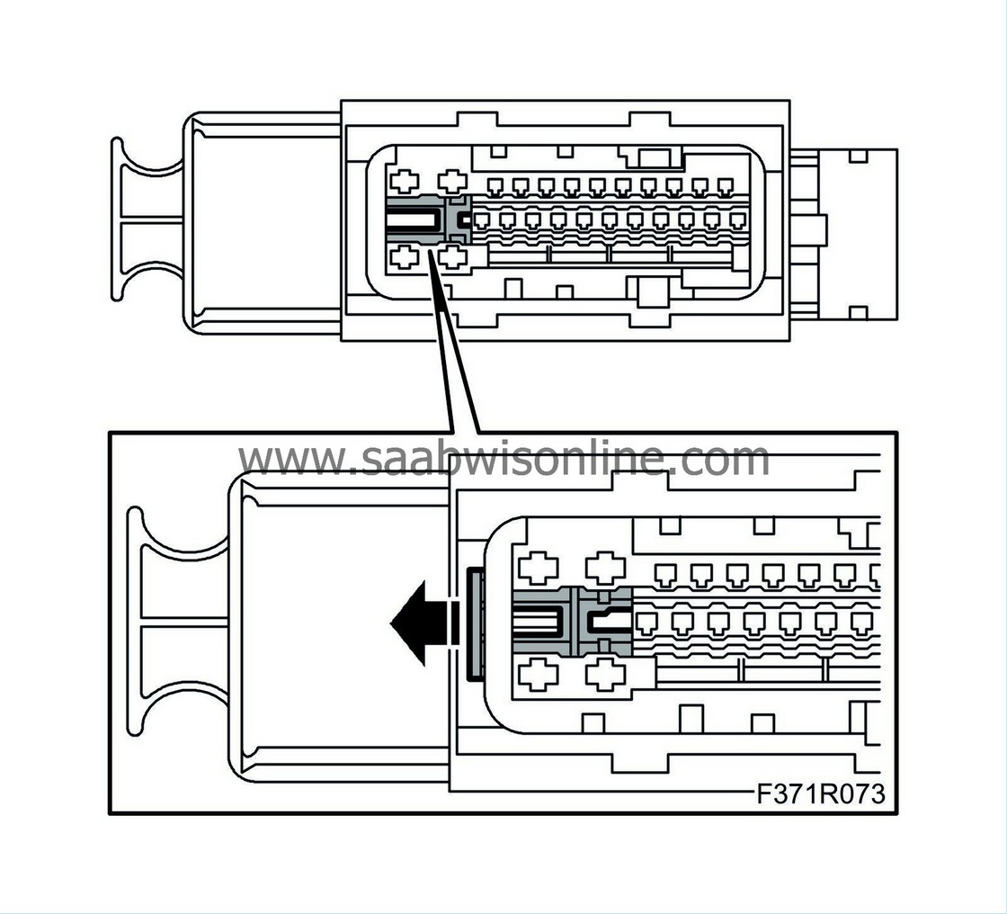
Loosen the secondary lock by pulling it out (about 2 mm) to the first notch.
|
|
| 4. |
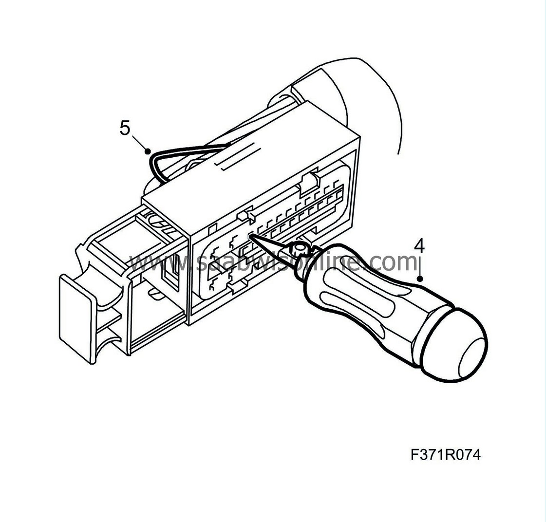
Undo the sleeve lock by pressing in the sleeve removal tool (part no. 85 80 151).
|
|
| 5. |
Pull out the cable with the sleeve.
|
|
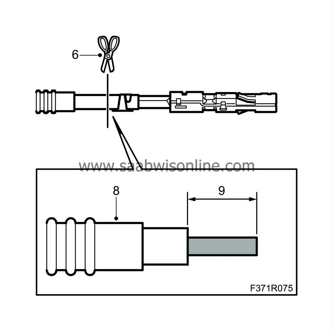
| 6. |
Cut the cable at the sleeve.
|
|||||||
| 7. |
If the cable is not long enough, it must be spliced as follows:
|
|
| 7.1. |
Strip the insulation on the cables.
|
| 7.2. |
Fit a shrink hose with adhesive on the cable.
|
| 7.3. |
Fit the splice sleeve (0.5 - 1.0 mm²), use blue pliers from 86 12 939 Toolbox, wiring harness.
|
|||||||
| 7.4. |
Place the shrink hose over the splice sleeve.
|
| 7.5. |
Heat the shrink hose to secure it.
|
| 8. |
Place the seal on the cable. Replace with a new one if necessary.
|
|
| 9. |
Strip 4 mm of the cable insulation.
|
|
| 10. |
Find the connector in question in the spare parts catalogue/EPC to obtain the part number of the sleeve (cable terminal) to be used.
|
|
| 11. |
Fit a new sleeve on the cable using the olive green pliers (0.35-0.75 mm²) from 86 12 939 Toolbox, wiring harness. Do not clamp the seal in the sleeve.
|
|
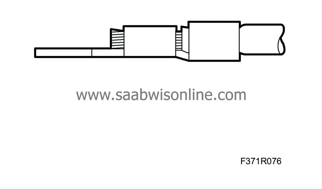
| 12. |
Make sure the stripped cable goes through all the clamped part of the sleeve and that the insulation is clamped securely.
|
|
| 13. |
Press the sleeve into the connector.
|
|
| 14. |
Check that the sleeve is locked securely.
|
|
| 15. |
Press the seal into the connector.
|
|
| 16. |
Make sure the new sleeve engages at the same depth as the other sleeves in the connector.
|
|
| 17. |
Press in the secondary lock.
|
|
| 18. |
Secure the cables with a cable tie.
|
|
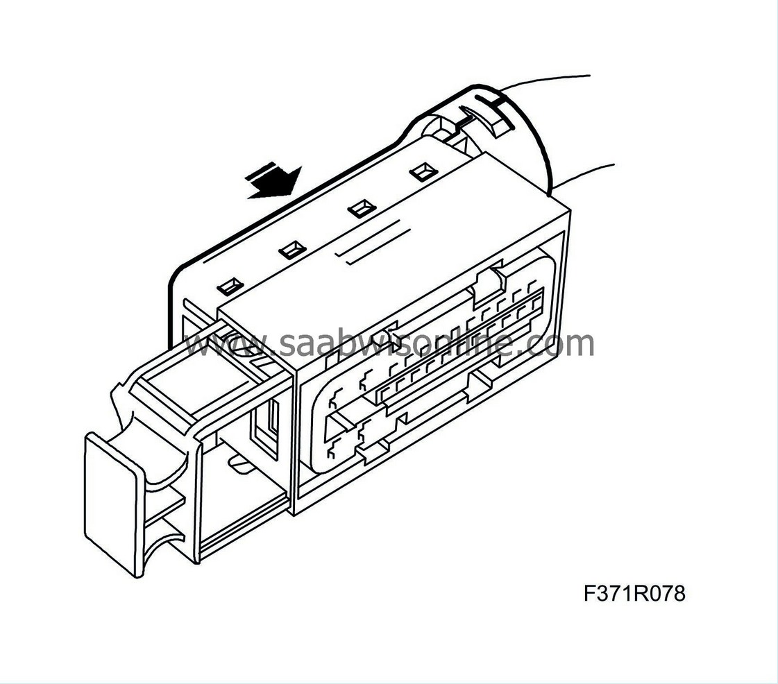
| 19. |
Fit the cover.
|
|
| 20. |
Make sure the control module pins are straight.
|
|||||||||||||
| To fit |
| 1. |
Plug in the connector.
|
|
| 2. |
Clear all diagnostic trouble codes.
|
|
| 3. |
Perform a driving cycle, i.e. drive the car under varying loads and engine speeds for five minutes.
|
|
| 4. |
Read diagnostic trouble codes.
|
|


